© 2002-12 PRINTED IN JAPAN
B53-0017-00 (N) 1874
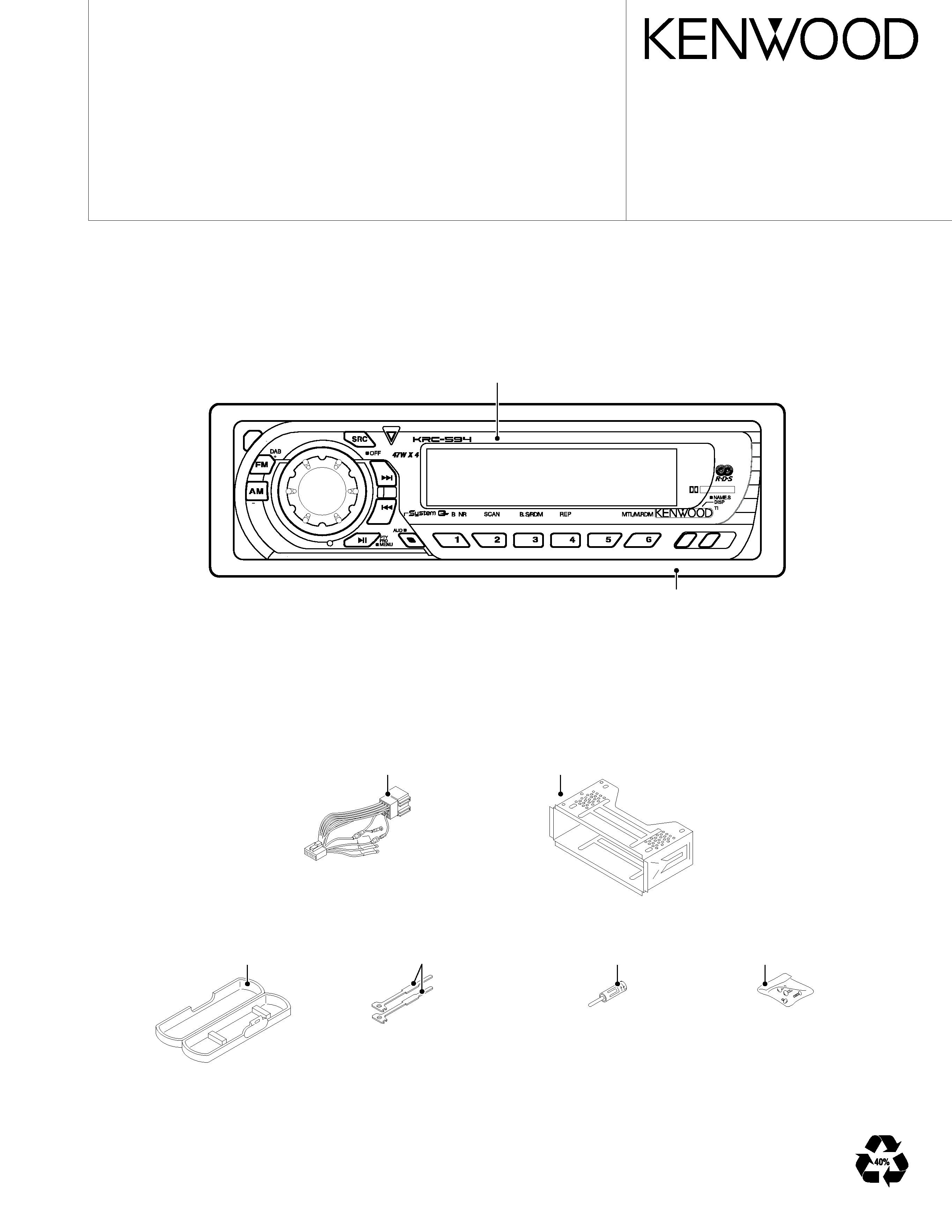
DC cord
(E30-4790-05)
Plastic cabinet assy
(A02-1486-13)
Lever
(D10-4589-04)x2
Mounting hardware assy
(J22-0011-03)
Antenna adaptor
(T90-0523-05)
Screw set
(N99-1730-15)
DOLBY B NR
Panel assy
(A64-2850-02): KRC-594 /Y
(A64-2852-02): KRC-594V/YV
Escutcheon
(B07-3083-02)
CASSETTE RECEIVER
KRC-594/V/Y/YV
SERVICE MANUAL
The CASSETTE MECHANISM OPERATION DESCRIPTION is the same model D40-1122-05.
Please refer to the service manual for model D40-1122-05 (B51-7452-00).
KRC-594/V/Y/YV
2
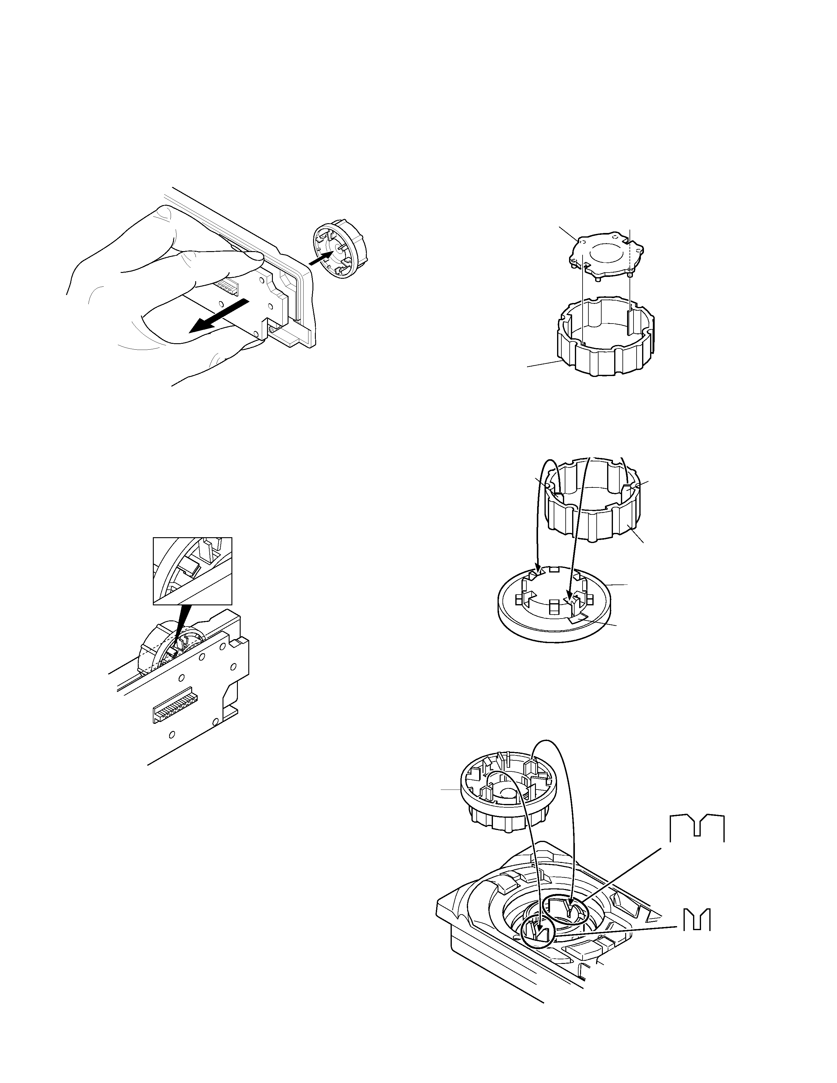
DISASSEMBLY FOR REPAIR
How to remove the Volume Knob
1. Remove the rear cover of panel unit.
2. Juck up as remove the switch unit (x16-) and Volume Knob
as shown.
(CAUTION)
Volume Knob cannot pull of front side that looked at tab
point in the rotary encoder.
LIGHTING BOARD
CAP
Be careful of direction.
Rib: tall
CAP
KNOB(VOL)
Dented part
Rib: short
How to install the Volume Knob
1. Remove the peeling paper of LIGHTING BOARD BOSS
side.
2. CAP and LIGHTING BOARD are install positioning as
shown.
5. Install a Volume Knob in rotary encoder positioning as
shown.
KNOB(VOL)
BROAD SIDE
OTHER SIDE
Mount the Volume Knob into
the broad Y shaped cutting in
the direction of the picture.
3. Remove the peeling paper.(Use Tweezers)
4. CAP and Volume Knob are install positioning as shown.
KRC-594/V/Y/YV
3
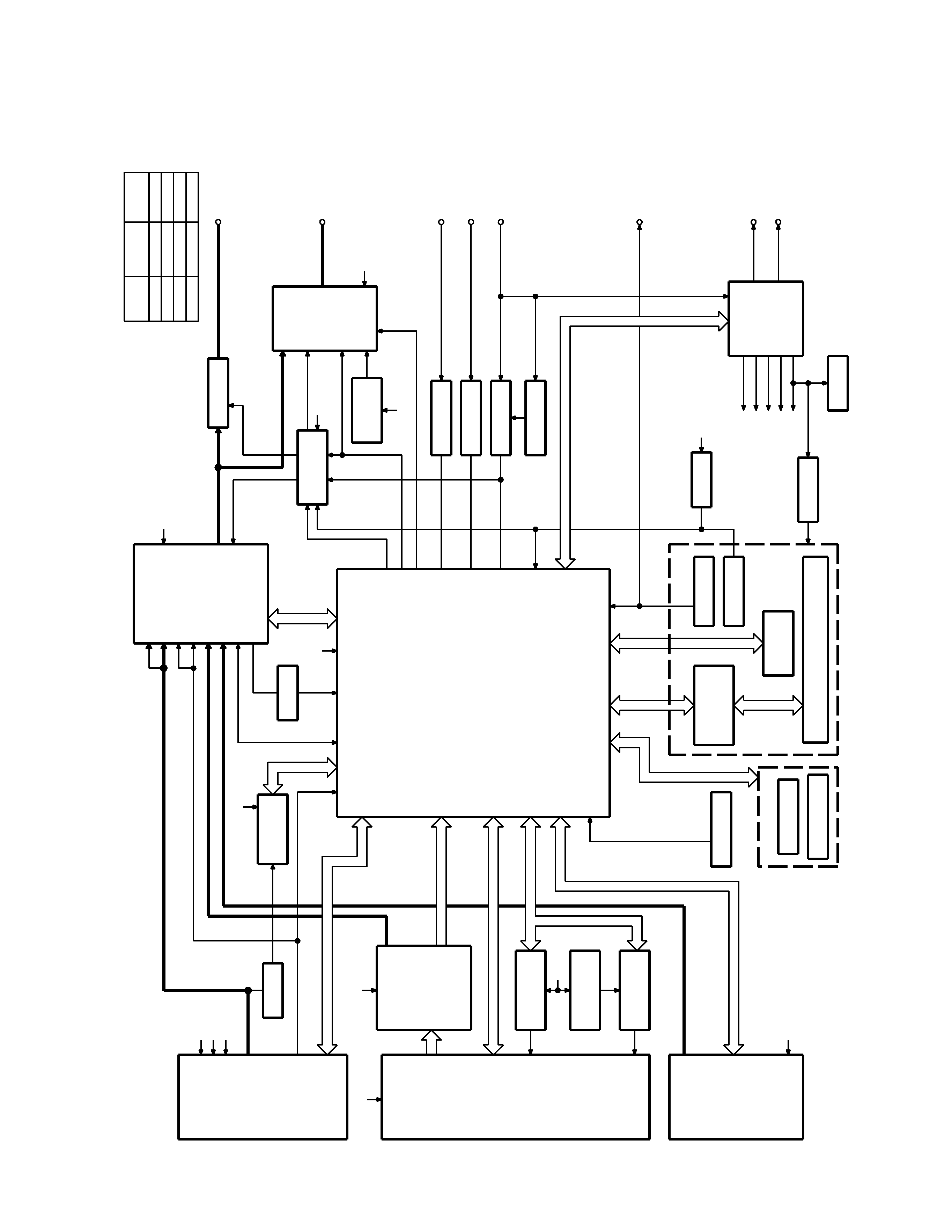
BLOCK
DIAGRAM
TUNER
CASSETTE
CH
BUFFER
RDS
DECODER
E-VOL
MPX
&
BUFFER
u-COM
DOLBY EQ
MOTOR
MAIN
AVR
SUB MOTOR
SUB MOTOR
DRIVER
PANEL 5V
EJECT ILLUMI
LCD
EJECT SW
PANEL DET
ROTARY
ENCODER
KEY MATRIX
LCD DRIVER
WITH
RESET SW
REMOCON
P CON
ANT CON
POWER
SUPPLY
IC
SW 5V
RESET
WIRED REMO
ACC DET
SURGE DET
B.U DET
TEL MUTE
BACK UP
TEL MUTE
ACC
SP OUT
POWER
IC
DRIVER
PROTECT
THERMAL
MUTE
PRE MUTE
PRE OUT
IC2
IC7
IC9
Q51
Q53
IC11
IC8
IC3
IC6
IC4
IC1
PLL-DATA
PLL-CLK
IFC OUT
AUDIO OUT
S-METER
SW5V
A8V
AM+B
SW5V
R
CLK
R
D
ATA
S-METER
QU
A
L
AFS
QUAL
MP IN
LEVEL
TAPE
CH
AM
FM
MODE2
MODE3
SUB-
MOT +B
SUB+
MODE1
FOR(L)
FOR(R)
REV(L)
R REEL
F REEL
REV(R)
MTL ON/OFF
DOLBY ON/OFF
MUTE
MS OUT
MS MODE
F/R
SW5V
A8V
BACK UP
SUB-
SUB+
MOT +B
LX REQ M
BACK UP
LX RST
LX MUTE
LX DATA S
LX DATA M
LX CON
LX CLK
LX REQ S
BU5V
I2C
D
A
T
A
I2C
CLK
PANEL
EJECT
ILL
EJECT
REMO
V
OLUME
B
V
OLUME
A
L
D
ATA
L
L
CE
L
D
ATA
S
L
CLK
ILLUMI
BU5V
A8V
FM+B
AM+B
BU5V
ACC DET
B.U DET
PHONE
EN1
EN2
EN3
RST
BEEP
P-MUTE
MUTE
BACK UP
BU5V
SW5V
3600mV
600mV
1800mV
1800mV
K,M-TYPE
FM
CH
AM
TAPE
MODE
1372mV
3600mV
855mV
1800mV
E-TYPE
A8V
DET
KRC-594/V/Y/YV
4
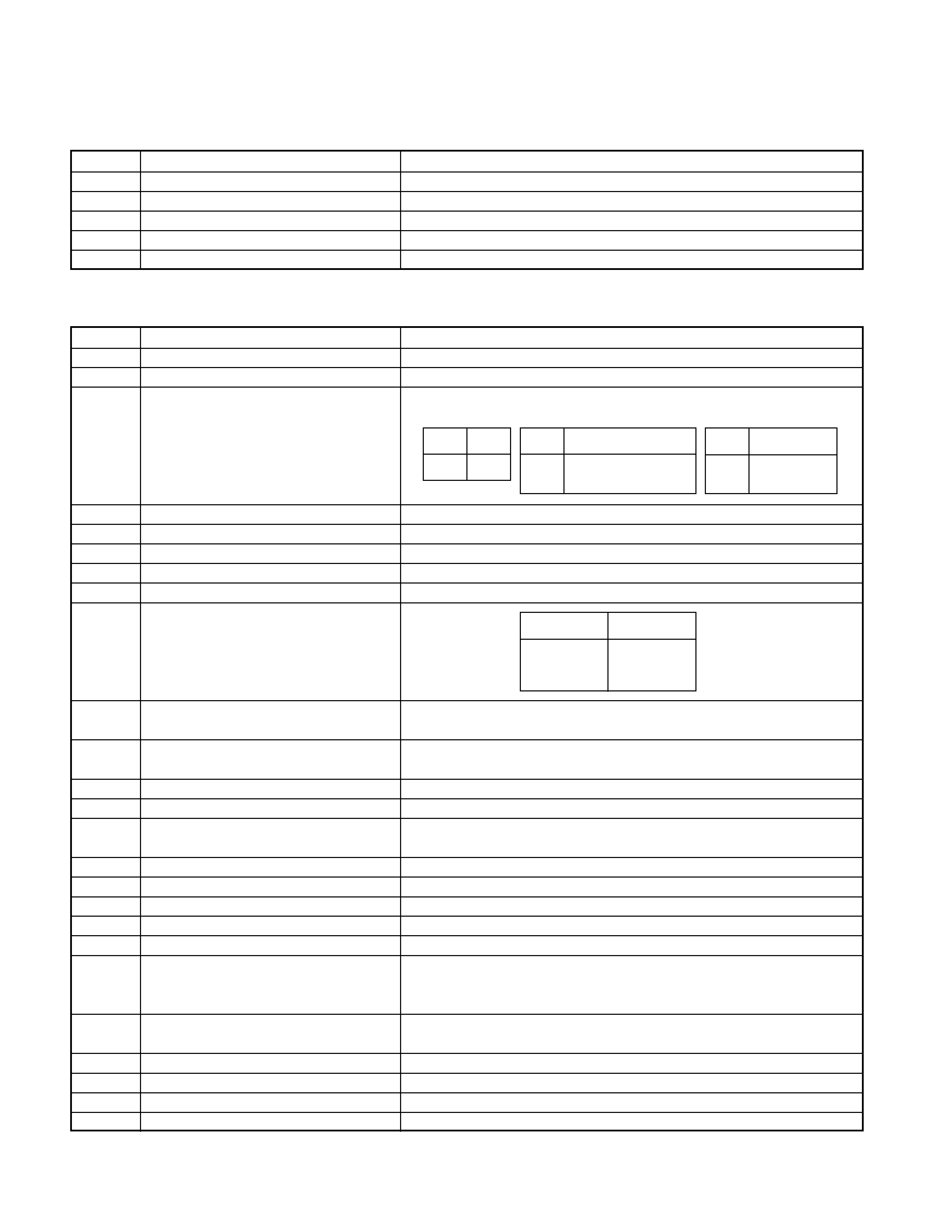
q SWITCH UNIT (X16-2032-7x)
COMPONENTS DESCRIPTION
Ref. No
Purpose ¡ Function
Operation/Condition/Compatibility
IC1
LCD driver
Drives LCD
IC2
Remote control IC
Controls the unit
Q1,Q4
REMO ON switch
The power supply of IC2 is turned on when base level goes "L"
Q2
Key Illumination switch (Green)
Lights Green key-illumination when base level goes "H"
Q3
Key Illumination switch (Red)
Lights Red key-illumination when base level goes "H"
q SYNTHESIZER UNIT (X14-9182-71)
Ref. No
Purpose ¡ Function
Operation/Condition/Compatibility
IC1
System
µ-com
Controls FM/AM tuner, the changer, cassette mechanism, Panel, volume and tone.
IC2
E.Vol & N.C.MPX
Controls the source, volume, tone and FM multiplex detector.
IC3
Power supply IC
BU5V(5V) Audio8V(8V) FM+B(8V)
AM+B(8V) P-CON ANT-CON
IC4
Power IC
Amplifies the front L/R and the rear L/R to 50W or 47W maximum.
IC6
Muting logic IC
Controls logic for muting.
IC7
RDS decoder
IC8
Reset IC
"L" when detection voltage goes below 3.5V or less.
IC9
Equalizer amplifier
Dolby-B, Metal-EQ, Equalizer the Tape sound(120
µ sec).
IC11
Sub motor driver
Sub motor control
Q1
Serge detection
"L" when the back-up voltage becomes more than 18V(momentary power down).
"H" when the back-up voltage becomes less than 18V.
Q2
BACK-UP detection
"L" when B.U is present.
"H" when B.U is absent or momentary power down is detected.
Q3
ACC detection
"L" when Acc is present.
Q4
SW 5V
ON when the base is "L".
Q5
Power-antenna detection
"H" when P-ANT output is short-circuit(P.ANT OFF).
"L" when FM/AM signal does not exist.
Q51
Main motor switch 1
Outputs 14V when the base is "L".
Q52
Main motor switch 2
Q51 turns ON when the base is "H" .
Q53
Sub motor AVR
Output 3.6V when the base of Q4 is "L".
Q54
MSTC switch
ON when the base is "H" .
Q101
Composite signal buffer
Q151
DSI driver
DSI lights when the base is "L".
DSI turns off when the base is "H" .
DSI turns on and off when panel is taken off.
Q152
Panel 5V switch
When the panel is attached, the base goes "L", turning the Tr ON to supply 5V
to the panel. When panel is taken off, panel 5V cut off.
Q201
Noise buffer
Q350
Pre mute switch
Drives the pre mute switch (Q351~354) when the base is "L".
Q351
Pre mute switch
Mutes the rear Lch when the base is "H".
Q352
Pre mute switch
Mutes the rear Rch when the base is "H".
EN1
ILLUMI
0V
OFF
5V
ON
IN
OUT
EN2
AM
FM
A8V
0V
OFF
OFF
OFF
2.5V
OFF
ON
ON
5V
ON
OFF
ON
IN
OUT
EN3
ANT-CONP-CON
0V
OFF
OFF
2.5V
OFF
ON
5V
ON
ON
IN
OUT
IN
SUB MOTOR
IN1()
IN2(+)
L
L
STOP
LH
CW
H
L
CCW
H
H
STANBY
KRC-594/V/Y/YV
5
MICROCOMPUTER'S TERMINAL DESCRIPTION
q SYSTEM MICROCOMPUTER MN101C49HNA (IC1: X14-)
Pin No.
Name
Module
I/O
Description
Processing Operation
1
VREF-
Power supply
GND for A/D
2
F REEL
TAPE
I
Reel pulse FWD
Cassette mecha reel pulse output FWD Vth=2.5V
3
R REEL
TAPE
I
Reel pulse REW
Cassette mecha reel pulse output REW Vth=2.5V
4
S-METER
TUNER
I
K3I tuner S-meter
5
IFC-OUT
TUNER
I
IF count
0V or 5V
6
NOISE
TUNER
I
FM noise detection terminal
7
PHONE
EXTRA
I
PHONE detection terminal
Tel mete :1V or less, NAVI MUTE:2.5V or less,
Only J type 1V or less,more than 2.5V NAVI
7
PHONE
EXTRA
I
When Not used, output L fixed
8
DCDET RESERVE Power supply
I
Not used DE DET pull down
DC offset detection terminal of P-IC
9
GND
Power supply
GND
10
VREF+
Power supply
VCC for A/D
11
VDD
Power supply
Microcomputer's main Vcc
12
MAIN OSC1
Main oscillation input
8.38MHz
13
MAIN OSC2
Main oscillation input
14
VSS
Power supply
Microcomputer's main GND
15
SUB OSC1
32.768kHz oscillation input
16
SUB OSC2
32.768kHz oscillation input
17
GND
Power supply
GND
External ROM
18
LX-DATAM
LX
O Data output to CH
Last maintain
19
LX-DATAS
LX
I
Data input from CH
20
LX-CLK
LX
O Clock input and output with CH
21
FLASH READ
O
22
FLASH WRITE
O
23
FLASH CLK
O
24
BEEP
AUDIO
O Beep for built in amplifier
25
PANEL-DET
to PANEL
I
Panel existence detection terminal
Detached the panel :L, Attached the panel :H
26
REMO
to PANEL
I
Remote control input
27
R-CLK
TUNER
I
Clock for RDS decoder
With no destination:out put L fixing
27
NC
O With no RDS output L fixed
28
LX-REQS
LX
I
Request input from CH
Request detection :L
29
B.U-DET
Power supply
I
Momentary power down detection
BU detection :L
With no BU :H
30
EJECT
to PANEL
I
Tape eject
L :KEY input
31
KEY-REQ
to PANEL
I
Communication request from LCD driver
L :KEY input
32
VDD
Power supply
I
VDD
33
RESET
I
Reset
During tape play :L
34
EQ MUTE
TAPE
O Equalizer mute
During tape FF/REW :H
Mode except tape :H
35
DOLBY
TAPE
O B NR ON/OFF
B NR ON:H,
B NR OFF:L
Mode except tape :keep the value
36
MUSIC
TAPE
I
Tape between music detection
music signal detection:L, with no music signal:H
37
NC
O
38
NC
O
39
NC
O
40
NC
O
41
VDD
Power supply
I
VDD
42
L DATAS
to PANEL
O TXD for LCD
43
L DATAL
to PANEL
I
RXD for LCD
44
L CLK
to PANEL
O Clock for LCD
45
PLL DATA
TUNER
I/O Tuner I2C SDA
46
NC
O