© 2002-10 PRINTED IN JAPAN
B51-7982-00 (N) 2139
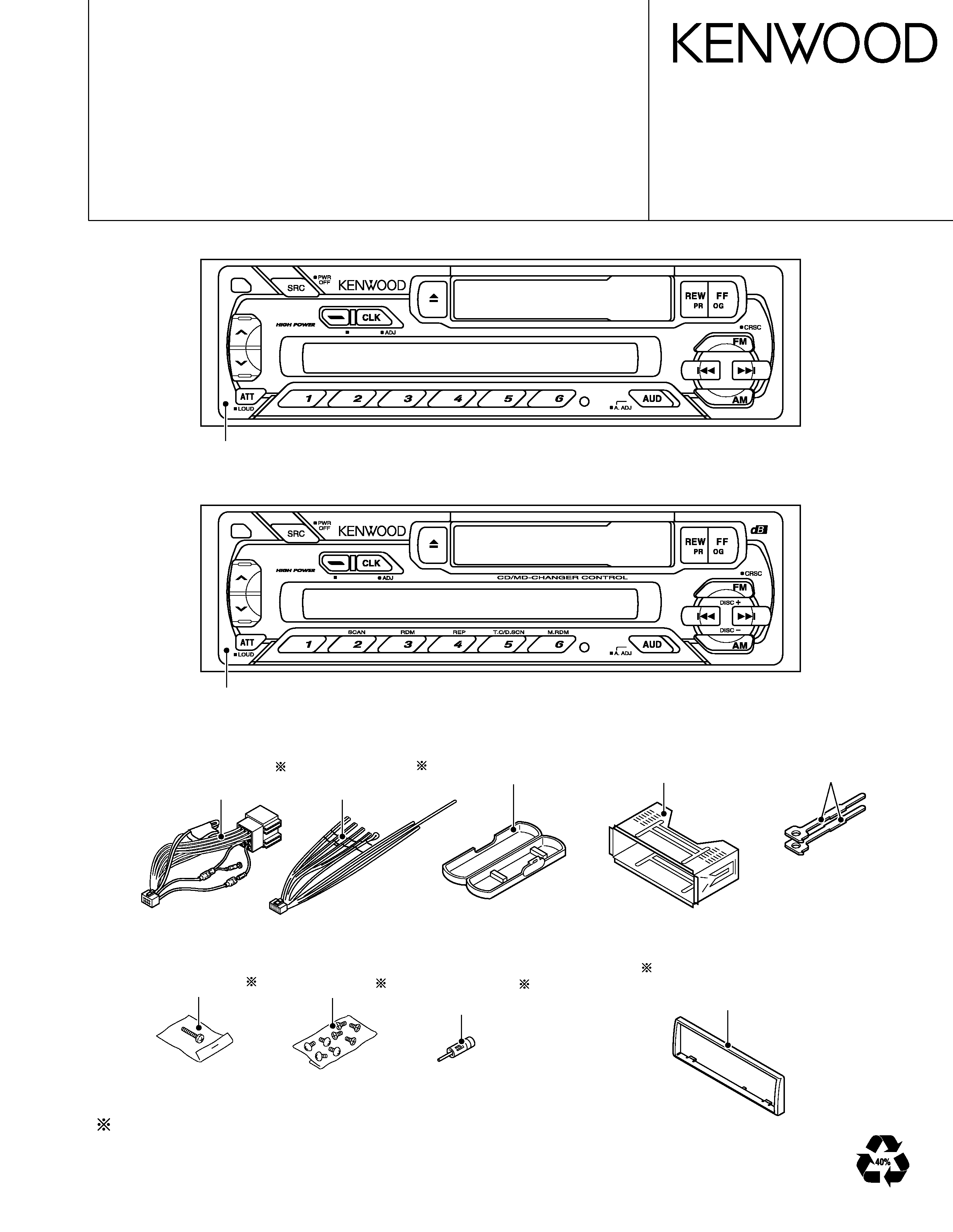
KRC-21SA/SG/SYA/SYG (E type)
KRC-266/S (M type)
Mounting hardware assy
(J21-9701-03)
Plastic cabinet assy
(A02-1486-13)
Lever
(D10-3031-04) x2
Depends on model. Refer to the parts list
Screw set
(N99-1610-15)
Screw set
(N99-1719-05)
KRC-21S
40W x 4
T.CALL
AUTO
AME
KRC-266
45W x 4
AUTO
AME
DC cord
(E30-4790-05)or
(E30-6134-05)
DC cord
(E30-4784-05)or
(E30-6131-05)
Antenna adaptor
(T90-0523-05)or
(T90-0534-05)
Panel assy (A64-2926-02)
Panel assy (A64-2915-02):KRC-266, (A64-2918-02):KRC-266S
Escutcheon
(B07-2188-02):KRC-21SA/SG/SYA/SYG, KRC-266
(B07-3021-02):KRC-266S
CASSETTE RECEIVER
KRC-21SA/SG/SYA/SYG
KRC-266/S
SERVICE MANUAL
KRC-21SA/SG/SY
A/SYG
KRC-266/S
2
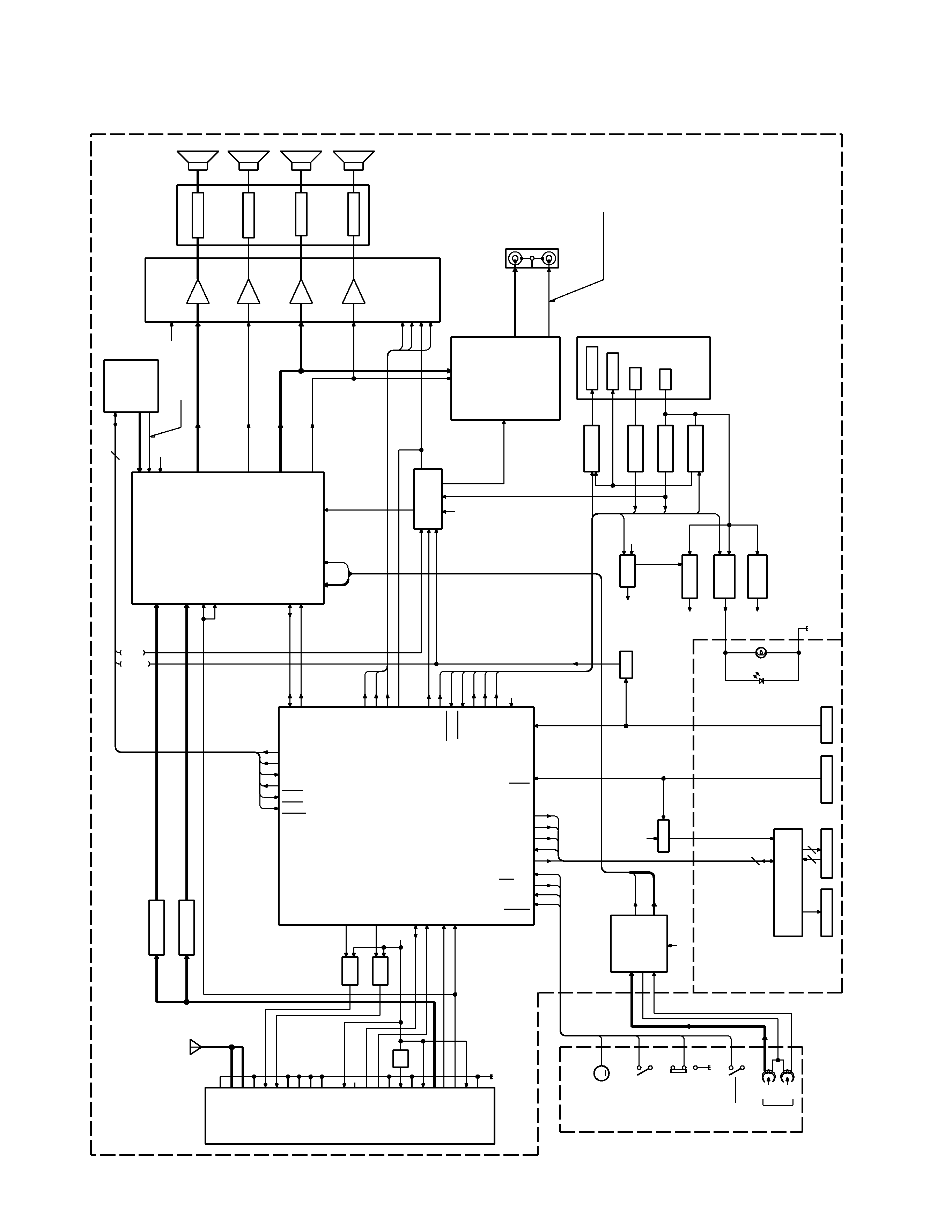
BLOCK
DIAGRAM
IC1
KEY
PAN 5V
MUTE
B.U. DET.
B.U.
ACC
P-CONT.
MUTE
PRE
POWER IC
EQ. AMP.
E-VOL.
CD/MD
CHANGER
FRONT Lch
FRONT Rch
REAR Lch
REAR Rch
J2
LCD DRIVER
LCD
CME1
MAIN
TAPE MECHA.
IC5
Lch
Rch
PRE OUT
IC2
IC4
IC3
SP OUT
REAR
J4
PAN IN SW
ACC DET.
P-CONT.
J2
J5
IC1
F/E
J1
FM+B
Q201
AM+B
Q203
AM BPF
FM BPF
C154,R206
C153,R207
Q320
Q450,451
Q49
Q50
Q350,351,370
Q53
SW 5V
Q54-57
8V
Q58-61
ILLUMI.
B.U. 5V
Q51,52
SYSTEM u-COM
S1
S2
S3
RST SW
Q301
D1-15
PL1,2
ANT.
ANT CONT
RST
ED1
FM ANT
AM ANT
RF GND
FM+B
AM+B
OSC GND
OSC GND
OSC GND
VT
PLL +B
IFC OUT
SDA
SCL
DIG GND
IF1+B
IF1 GND
S-METER
IF2 GND
SD
FM+B
P.ON
ACC DET
B.U. DET
SCL
MUTE
SDA
P CON
P
ANEL
HOLD
L
CLK
L
D
ATA
S
L
D
ATA
L
FWD/REV
M
OTO
R
CH
CON
D
ATA
H
D
ATA
C
REQ
H
REQ
C
CH
CLK
Rch
COM
Lch
MP IN
AM
MPX
OUT RR
OUT LR
OUT RF
Rch
LEVEL
SCL
SDA
OUT LF
Rch
STBY
MUTE
Rch
Lch
T-MUTE
FWD
REV
B.U.5V
8V
B.U.
CH
RST
S
MUTE
8
5
10
B.U.5V
AM+B
VDD 5V
P
A
CK
IN
L
RES
ANT CON
CH
MUTE
BEEP
SVR
AMP. STBY
SVR
AC GND (BEEP)
Lch
Lch
Rch
Lch
1200mV
TAPE :1681mV
CD/MD-CH :3529mV
AM :546mV
FM :1781mV
8V
RF GND
OSC GND
IF2 +B
AUDIO OUT
8V
S-METER
SD
PLL-SCL
PLL-SDA
CM1
PLAY
HEAD
L/R
55.6mV
B.U.5V
SW 5V
8V
B.U.5V
AM: 170mV
FM: 400mV
TAPE
PACK IN
(FF/REW)
AMP. MUTE
FF/REW
B.U.5V
ILL
L
CE
(X16)
A1
ANT CONT
D380
5V
R205
M
KRC-21SA/SG/SYA/SYG
KRC-266/S
3
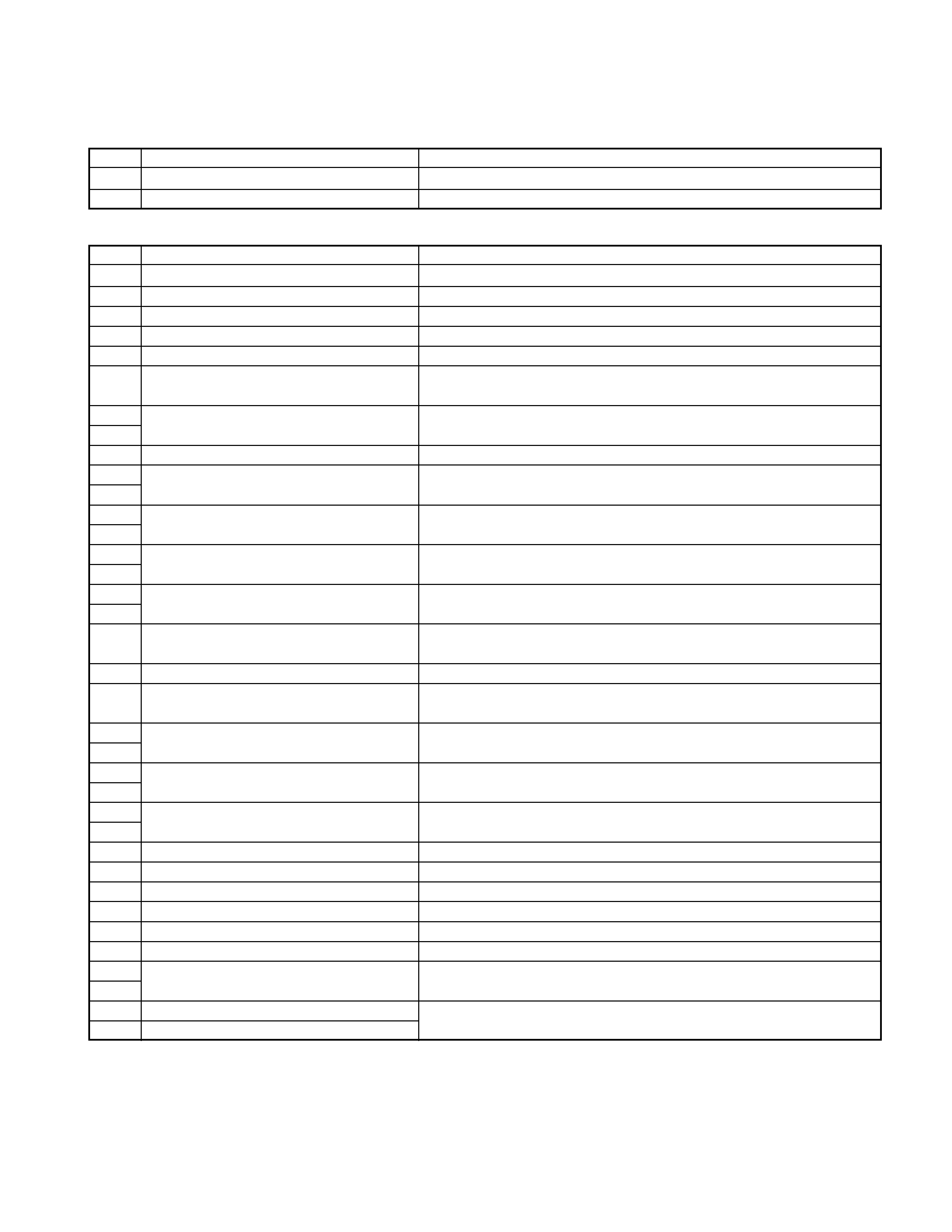
q SYNTHESIZER UNIT (X16-149x-xx)
COMPONENTS DESCRIPTION
Ref.No.
Application/Functions
Operation/Condition/Compatibility
IC1
LCD driver with key-matrix
Q1
Key-matrix permission SW
Ready on key-matrix
q SYNTHESIZER UNIT (X14-685x-xx)
Ref.No.
Application/Functions
Operation/Condition/Compatibility
IC1
System MI-COM.
System control
IC2
E-VOL. & N.C. MPX
Controls sound volume. Selects each source.
IC3
Mute logic
3-input NOR gate x 3
IC4
Power IC
Amplifies power so that the speaker can drive audio signal.
IC5
Equalizer amplifier
Equalizer amplifier for cassette tape sound
Q50
BACK-UP detection(Momentary
power down detection) SW
While BACK-UP is added, a base becomes Hi, and Q50 is turned on.
Q51
BACK-UP 5V AVR
While BACK-UP is added, AVR outputs +5V.
Q52
Q51 and Q52 is inverted Darlington connection.
Q53
P.ON 5V SW
While a base becomes Lo, Q53 is turned on.
Q54
COM+B SW
While Q54's base becomes Hi, Q55 is turned on.
Q55
Works during POWER ON mode.
Q56
COM+B AVR
While Q57's base becomes Hi, Q56 is turned on.
Q57
Q56 and Q57 is inverted Darlington connection.
Q58
Illumination +B SW
While Q58's base becomes Hi, Q59 is turned on.
Q59
Works during POWER ON mode with a panel attached to the set.
Q60
Illumination +B AVR
While Q61's base becomes Hi, Q60 is turned on.
Q61
Q60 and Q61 is inverted Darlington connection.
Q150
Electric volume mute SW
When BACK-UP detection SW or CHANGER RESET SW or MI-COM.'s mute
works, a base becomes Hi, and Q150 is turned on.
Q151
SVR discharge SW
When POWER IC RESET is activated, a base becomes Hi, Q151 is turned on.
Q153
Pre-out mute driver
When BACK-UP detection SW or CHANGER RESET SW or MI-COM.'s mute
works, a base becomes Lo, and Q153 is turned on.
Q200
FM +B SW
Q201 is turned on when Q200's base becomes Hi.
Q201
Works during FM reception mode.
Q202
AM +B SW
Q203 is turned on when Q202's base becomes Hi.
Q203
Works during AM reception mode.
Q260
Motor +B SW
When Q260's base becomes Hi, Q261 is turned on. Works during TAPE mode.
Q261
Q301
Changer reset SW
When a base becomes Lo, Q301 is turned on.
Q320
Panel 5V SW
While a panel is attached to the set, a base becomes Lo, and Q320 is turned on.
Q350
P-CON. driver
When Q353's base becomes Hi, Q350 is turned on.
Q351
P-CON. protection SW
Works when P-CON is being short-circuited on GND.
Q352
P-CON. protection inhibit SW
Inhibits protection SW function when P-CON works momentary.
Q353
P-CON. SW
Q353 is turned on when a base becomes Hi. Works during POWER ON mode.
Q370
ANT-CON. SW
Q370 is turned on when Q371's base becomes Hi.Works during TUNER mode.
Q371
Q450
Pre-out mute SW (R ch.)
When BACK-UP detection SW or CHANGER RESET SW or MI-COM.'s mute
Q451
Pre-out mute SW (L ch.)
works, a base becomes Hi, and Q450,451 are turned on.
KRC-21SA/SG/SYA/SYG
KRC-266/S
4
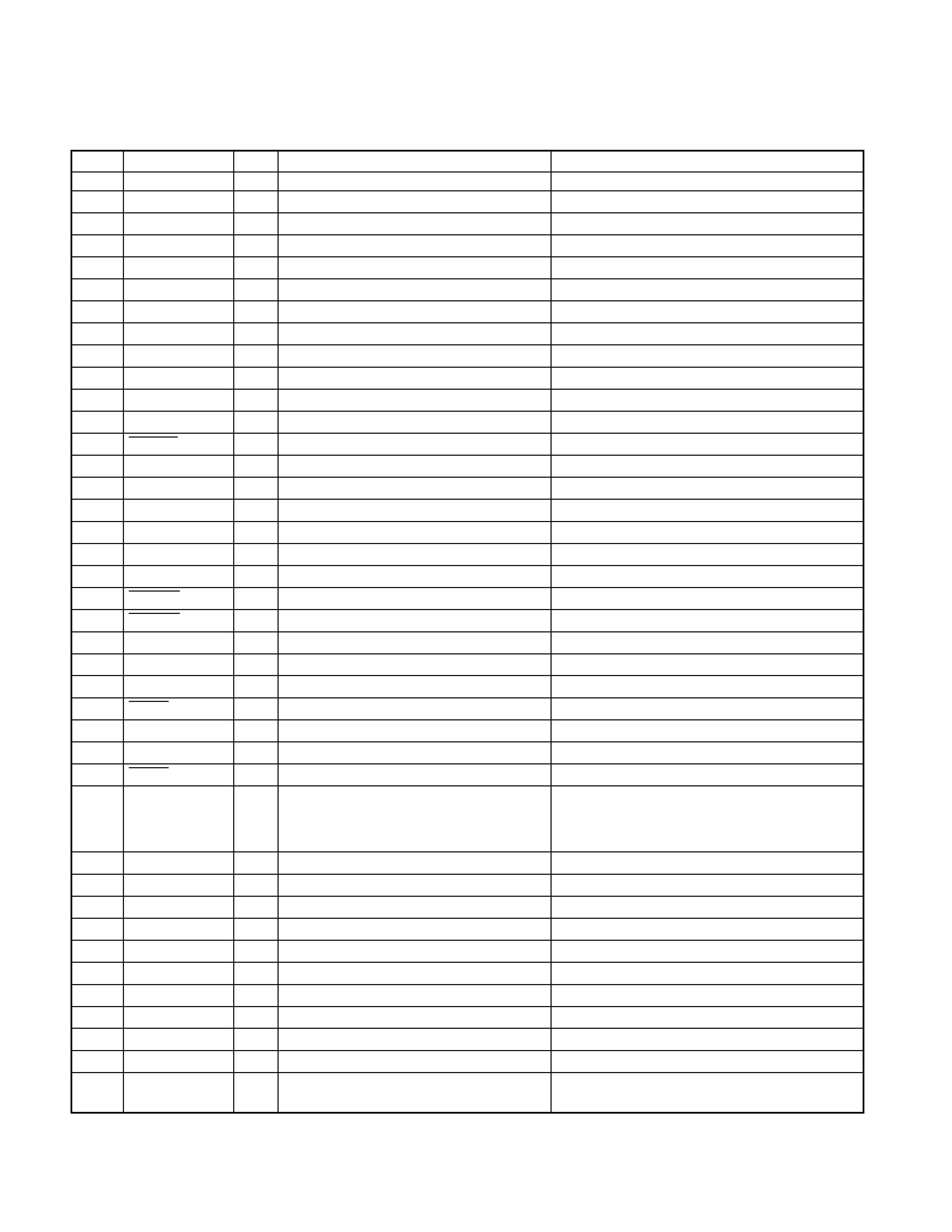
MICROCOMPUTER'S TERMINAL DESCRIPTION
q SYSTEM MICROCOMPUTER LC72366-9592 (IC1 : X14-685x-xx)
Pin No.
Pin name
I/O
Description
Processing Operation
1
XIN
I
Main clock resonator connection terminal
2
GND
-
TEST terminal 2
Connected to GND lines.
3
L DATA L
I
Data input from the LCD driver IC
4
L DATA S
O
Data output to the LCD driver IC
5
L CLK
O
Clock output to the LCD driver IC
6
L CE
O
CE output to the LCD driver IC
7
SDA
I/O
Data input/output with the E-VOL. IC
8
PLL DATA
I/O
Data input/output with the F/E
9
PLL CLK
O
Clock output to the F/E
10
SD
I
SD input from the F/E
Hi : Station detected
11
DATA C
I
Data input from changers
12
DATA H
O
Data output to changers
13
CH CLK
I/O
Clock input/output with changers
14
-
O
-
N.C. (Not used)
15
MOTOR
O
Cassette motor on/off output
Hi : Motor ON
16
SCL
O
Clock output to the E-VOL. IC
17-24
-
O
-
N.C. (Not used)
25
AM+B
O
AM+B ON/OFF output
Hi : during AM reception
26
FM+B
O
FM+B ON/OFF output
Hi : during FM reception
27
PACK IN
I
Cassette tape Pack-in detection input
Lo : Pack-in
28
FF/REW
I
FF/REW detection input
Lo : FF/REW, Hi : PLAY
29
GND
I
-
Connected to GND lines.
30
GND
I
-
Connected to GND lines.
31
VDD
-
Positive power supply connection terminal
Connected to B.U. 5V lines.
32
REQ C
I
Request input from changers
Lo : Request
33
MUTE
O
Audio mute on/off output
Hi : Mute ON
34
CH CON
O
Changer control
Lo : Standby, Hi : ON
35
REQ H
O
Request output to changers
Lo : Request
When the momentary power down, after ACC
36
SVR
O
Power IC reset terminal
ON/OFF is detected and after POWER OFF,
the output becomes Hi temporarily.
37
AMP STBY
O
Power IC standby control output
Hi : POWER ON mode
38
AMP MUTE
O
Power IC mute control
Lo : Mute
39
P CON
O
Power control
Hi : POWER ON mode
40
ANT CON
O
Antenna control
Hi : during FM/AM reception
41
SW5V
O
SW 5V control
Lo : POWER ON mode
42
ILL
O
Illumination AVR ON/OFF control terminal
Hi : POWER ON mode
43
-
O
-
N.C. (Not used)
44
BEEP
O
BEEP sound output
45-47
-
O
-
N.C. (Not used)
48
ROLL OFF
I
Roll off input
Pull down to GND lines. (Not used)
49
NOISE
CANCELLER
I
Noise canceller input
Pull down to GND lines. (Not used)
KRC-21SA/SG/SYA/SYG
KRC-266/S
5
MICROCOMPUTER'S TERMINAL DESCRIPTION
q SYSTEM MICROCOMPUTER LC72366-9592 (IC1 : X14-685x-xx)
Pin No.
Pin name
I/O
Description
Processing Operation
50
SEL1
I
Destination input 1
Hi : KRC-21S
51
SEL2
I
Destination input 2
Hi : KRC-21S
52
SEL3
O
Destination input 3
N.C. (Not used)
53
EQ MUTE
O
Tape equalizer mute on/off output
N.C. (Not used)
54
FWD/REV
I
FWD/REV mode detection input
Lo : REV mode
55
-
O
-
N.C. (Not used)
56
REMO
I
Data input from the remote control
N.C. (Not used)
light sensor
57-60
-
O
-
N.C. (Not used)
61
ACC DET
I
ACC detection input
Hi : ACC ON
62
B.U. DET
I
Momentary power down detection input
Hi : When momentary power down detected or
B.U. OFF, Lo : B.U. ON
63
S METER
I
S-meter input from the F/E
64
PANEL
I
Panel detaching detection input
Lo : Panel not detached
65
GND
I
-
Connected to GND lines.
66
GND
I
-
Connected to GND lines.
67
HOLD
I
MI-COM. HOLD input
Lo : Hold
68
VDD
-
VDD connection terminal
Connected to B.U. 5V lines.
69
GND
I
-
Connected to GND lines.
70
GND
I
-
Connected to GND lines.
71,72
-
O
-
N.C. (Not used)
73
VDD
-
Positive power supply connection terminal
Connected to B.U. 5V lines.
74
GND
I
-
Connected to GND lines.
75
GND
I
-
Connected to GND lines.
76
VSS
-
Ground connection terminal
Connected to GND lines.
77,78
-
O
-
N.C. (Not used)
79
GND
-
TEST terminal 1
Connected to GND lines.
80
XOUT
O
Main clock resonator connection terminal