
KPA-SD100
CONTROL ADAPTER
3page 2-7
INSTRUCTION MANUAL
MODE D'EMPLOI
STEUERUNGS ADAPTER
3Page 14-19
BEDIENUNGSANLEITUNG
BESTURINGS ADAPTER
3Page 20-25
GEBRUIKSAANWIJZING
ADATTATORE DEI COMANDI
3Page 26-31
ISTRUZIONI PER L'USO
ADAPTADOR DE CONTROL
3Page 32-37
MANUAL DE INSTRUCCIONES
ADAPTADOR DE CONTROLO
3Page 38-43
MANUAL DE INSTRUÇÕES
©PRINTED IN JAPAN B64-1747-20 (E) (DT)
ADAPTEUR DE COMMANDE
3Page 8-13
LA DICHIARAZIONE DI CONFORMITA' "CE"
DI QUESTO PRODOTTO E' DEPOSITATA
PRESSO:
KENWOOD ELECTRONICS EUROPE B.V.
AMSTERDAMSEWEG 37
1422 AC UITHOORN
THE NETHERLANDS
2-English
Applicable Models (Centre Units)
This product operates when connected to a model compatible with the Centre Unit.
For information on models compatible with the Centre Unit, see the attached table of
compatible models.
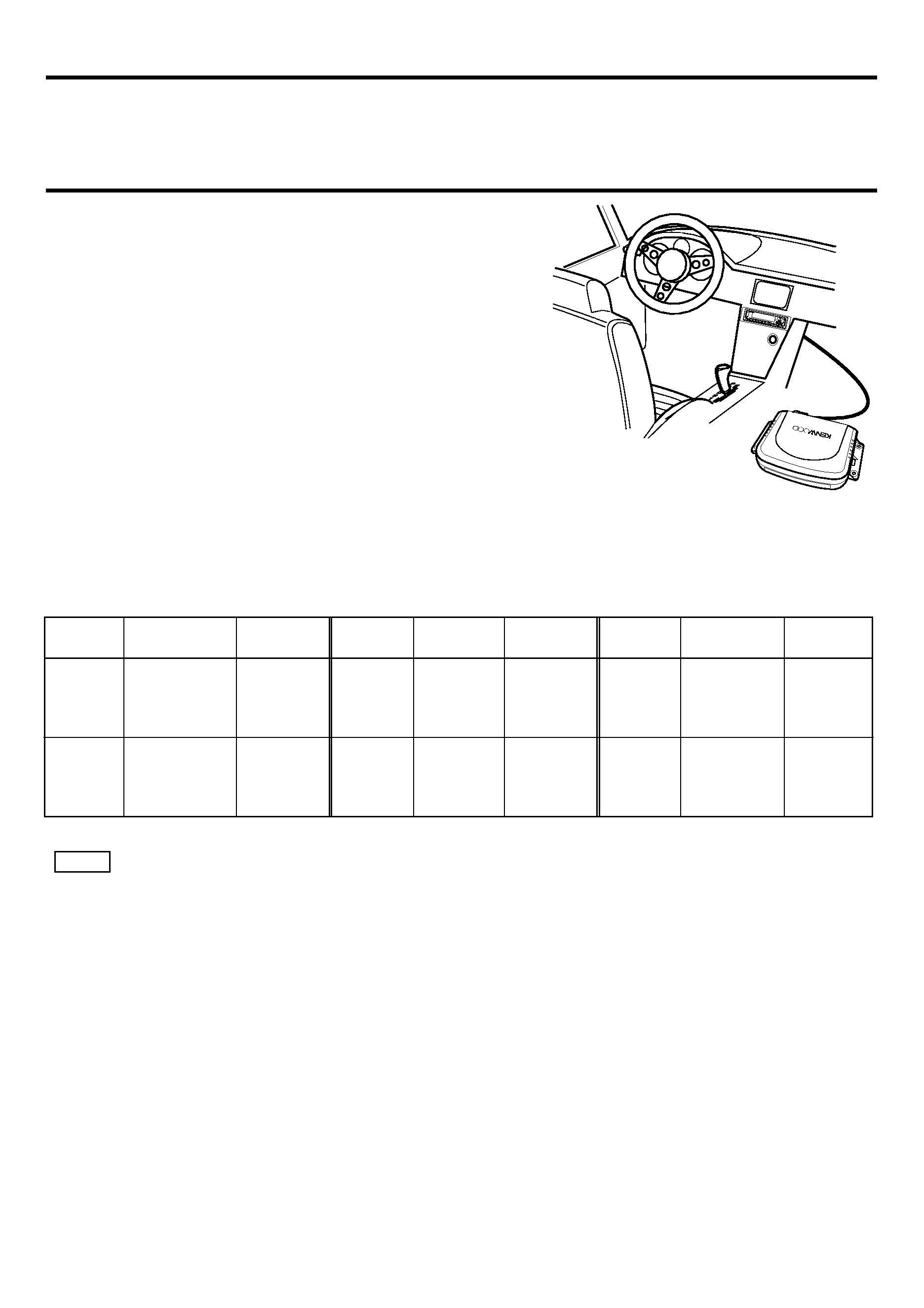
About this product
When connected to your vehicle, this product will
display information from the KENWOOD centre unit,
on the display screen installed in your vehicle.
It also enables the centre unit to be operated from the
remote controller on the steering-wheel.
*:Please confirm with Kenwood dealer whether this
product can accommodate to your OPEL car.
7 The kind of information that can be displayed on the display screen
(typical display appearing on 14-segment display screen)
The following information can be displayed on the in-car display screen.
*1:KENWOOD centre unit
· The information appearing on the display screen will vary when receiving MW / LW broadcasts, depending on the centre unit
model you are using.
· 14-segment display shows lower case characters and accented European language characters in upper case; the 5 x 7 dot
matrix display does not show accented European language characters.
· The information shown on the display screen will vary depending on whether you are using the 14-segment display screen or
the 5 x 7 dot matrix display screen.
NOTE
TUNER
TUNER
interrupt
DISC
CHANGER
CD,MD
TAPE
DAB
Source
Frequency
TI interrupt
Source
Time Code
Source
Source
Source
NEWS interrupt
ALARM interrupt
DPSS
Side
Time Code
Service Label
TUNER
100,05
SKYRADIO
TRAFFIC
NEWS
ALARM
CD
02 0'01
DISC
02 0'01
TAPE
A
30'00
+1
30'00
DAB
ABCDEFGH
Program Service
Mode
*1
Vehicle's
Display
Vehicle's
Display
Mode
*1
Mode
*1
Vehicle's
Display
CONTROL
ADAPTER
KP A-SD100
EJECT
PWR
OFF
LOUD
MENU
DISP
NAME.S
SCAN
RDM
REP
D.SCN
M.RDM
DISC
DISC
DAB
AUD
NF
AUTO
AME
English
-3
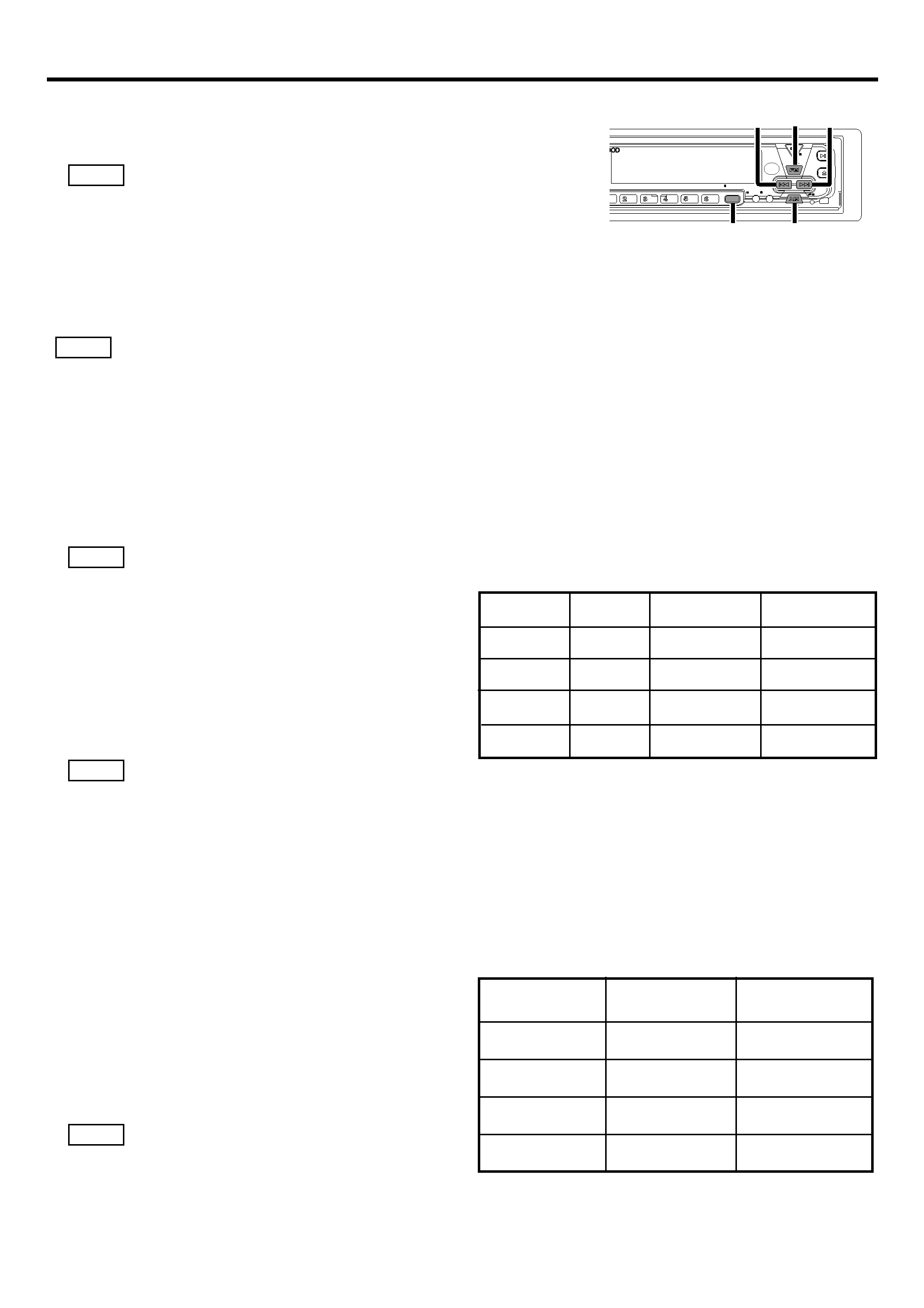
Operation
7 Vehicle's display setup
1. Select "EXT.ACC.CONT/ACC.CONT/EXT.ACC Control" from the
Centre Unit menu items.
This does not work during reception of MW / LW broadcasts(if the centre unit
displays the sensors, it is displayed as "- - - -").
2. Hold down the
4 or ¢ button for more than two seconds.
Centre Unit enters display-switching mode.
3. The display changes as follows when you press the
4 button or ¢ button.
Display switching:
O Sensor*2/Compass*3 O Music Source O
·*2: Sensor display appears when the Sensor Box (KPA-SS100) is connected.
·*3: Compass display appears when the Compass Unit (KPA-CP100) is connected.
· In Music Source display, the number of items switched, such as source display and track display, varies with the source
currently being played.
· The time reading on the vehicle's display and time reading on the centre unit display are not synchronized.
7 Compass setup (When the KPA-CP100 is connected)
By combining this unit with the KPA-CP100 (sold separately), the compass display can be
shown on the display screen.
1. Select "Sensor CONT/SENS.CONT/Sensor Control" from the Centre Unit menu items.
This does not work during reception of MW / LW broadcasts .
2. Hold down the
4 or ¢ button for more than
two seconds.
The Centre Unit enters Compass setup mode.
3. Press the FM or AM button.
Each pressing toggles setup mode as follows:
O Direction step switching O Compass
direction compensation
O Target direction setup
O
During the Compass setup procedure, the message "SENS.CNT" will be displayed on the vehicle's display screen.
4. At the item you want to set up, press the
4 or ¢ button.
Each item allows you to set the following:
Direction step switching:
Toggle direction display modes.
O North direction (8 directions) mode O North direction (16 directions) mode O
Target direction (8 directions) mode
O Target direction (16 directions) modeO
North direction mode
The vehicle's direction of travel will be displayed
with letters as one of the 8 or 16 compass
directions.
Target direction mode
In Target direction mode, you can set the desired
target direction, and any deviation from this
direction will then be displayed on the display .
(See "Target directions setup" for instructions on
setting the target direction.)
If it is displayed as "RIGHT 90.0/ R 90.0", the 90-degree
direction on the right is the direction of the destination.
NOTE
NOTE
NOTE
NOTE
NOTE
EJECT
PWR
OFF
MENU
DISP
NAME.S
SCAN
RDM
REP
D.SCN
M.RDM
DISC
DISC
DAB
AUD
NF
AUTO
AME
4
¢
FM
AM
MENU
Centre Unit
North directions
(8 directions)
North directions
(16 directions)
Target directions
(8 directions)
Target directions
(16 directions)
16-digit display
example(Centre Unit)
8-digit display
example(Centre Unit)
NORTH. DIR 8
NORTH. DIR 16
TARGET. DIR 16
TARGET. DIR 8
N. DIR 8
N. DIR 16
T. DIR 16
T. DIR 8
Display in adjustment mode
SENS.CNT
Vehicle's
display
SENS.CNT
SENS.CNT
SENS.CNT
North direction display
(8 directions)
16-digit display example
8-digit display and
vehicle's display example
DIRECTION
W
DIRECTION SW
DIRECTION
N
DIRECTION
NNE
BACK
180.0
LEFT
112.5
FORWARD
0.0
RIGHT
90.0
DIR
W
DIR SW
DIR
N
DIR NNE
B
180.0
L
112.5
F
0.0
R
90.0
Compass display example
North direction display
(16 directions)
Target direction display
(16 directions)
Target direction display
(8 directions)
4-English
Compass direction compensation:
1. Correct earth magnetism to allow the compass to operate normally.
The Centre Unit displays "COMPASS.ADJUST/COMP.ADJ" and enters the earth magnetism
direction setup verification mode.
2. Press the
4 or ¢ button. Automatic compensation starts. Upon entering automatic
compensation, turn the vehicle 360 degrees.
The compensation time lasts less than two minutes. (Compensation may not be achievable if
the vehicle does not finish turning 360 degrees within two minutes.)
If compensation is completed, the Centre Unit displays "OK".
· If compensation fails, the Centre Unit displays "NG".(If the correction results in "NG", previous correction values remain
as they are. )
· In Adjusting, if you press the
4 button or the ¢ button, this will forcibly render the status NG, and you will only be
able to change the Direction Compensation setting.
· When compensating earth magnetism, be sure
to operate the switch while stopped.
· When compensating earth magnetism, set the
steering angle at start and end to 0 (straight)
degree.
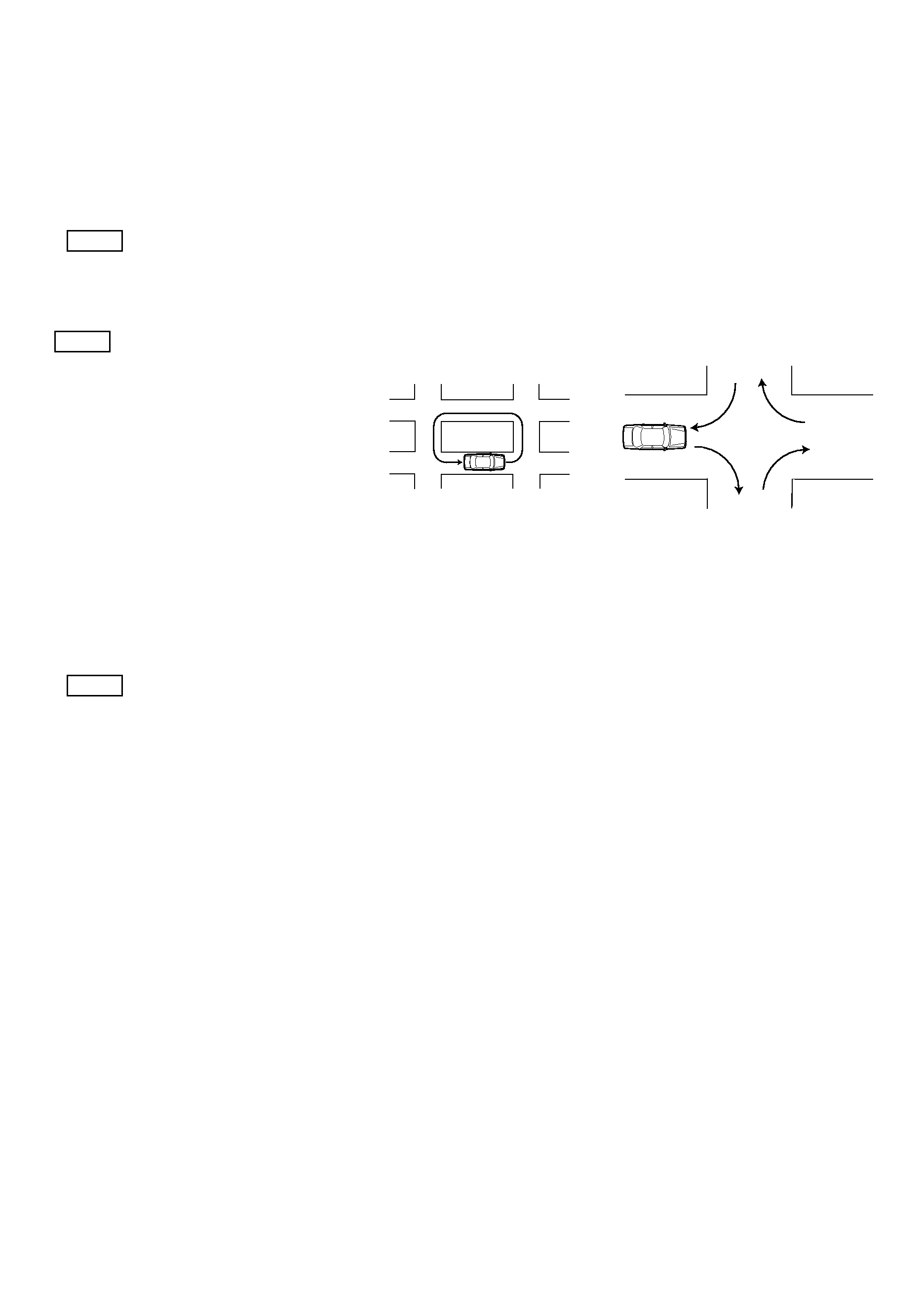
· If there is no location to revolve 360 degrees,
follow the procedure shown in the following
diagram. However, never make u-turns in heavy
traffic or at intersections since they are
dangerous.
3. About direction compensation
North on the map may not be exactly the same as magnetic pole north in some areas. To
compensate for this discrepancy, find the current region on the map in Figure 1(See back
cover), then set the value entered in for this region.
<Direction compensation>
Press the
4 or ¢ button to perform ±20-degree direction compensation.
20
O 15 O 10 O 5 O 0 O +5 O +10 O +15 O +20
The factory default is 0.
Target directions setup:
When you select the target direction by switching direction steps, specify the target direction.
Target direction can be specified from 8 or 16 directions.
O TGT/TARGET N O TGT/TARGET NNW O TGT/TARGET NW O TGT/TARGET WNW O
TGT/TARGET W
O TGT/TARGET WSW O TGT/TARGET SW O TGT/TARGET SSW O
TGT/TARGET S
O TGT/TARGET SSE O TGT/TARGET SE O TGT/TARGET ESE O
TGT/TARGET E
O TGT/TARGET ENE O TGT/TARGET NE O TGT/TARGET NNE O
NOTE
NOTE
NOTE
1To front
4To rear
3To front
2To rear
English
-5
Installation
7 Accessories
1Remote control light emitter (cable length:2.5m) ...1
4Connection cable (2m)......................1
2Connection cable(ISO AB :0.1m).............................1
5Self-tapping screw (Ø4 X16mm) ......4
3Connection cable(ISO C :2m) ..................................1
6Adhesive double coated tape ...........1
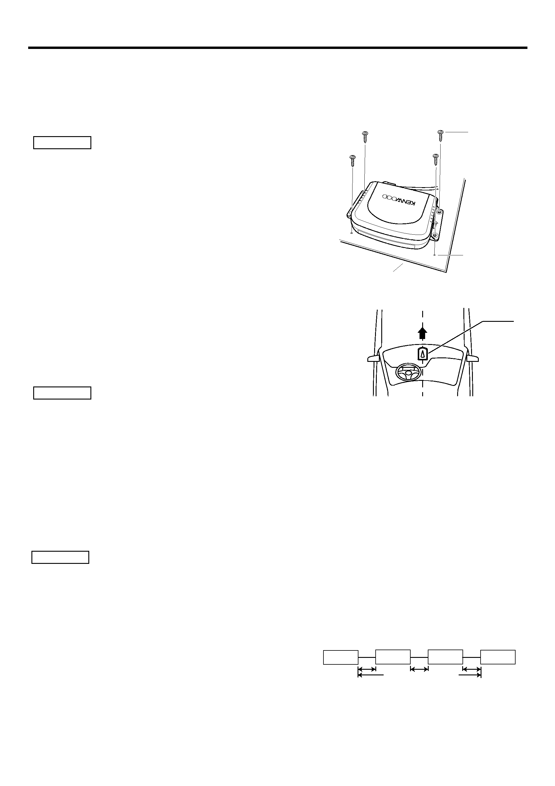
7 Installing the Control Unit
· When drilling a hole below a seat or inside the trunk, check if there is the gas
tank, brake pipe, or wire harness behind the hole in advance. If so, be careful
not to damage them in any way.
· Do not install the Control Unit on the dashboard, on the rear tray, or near any
safety component such as an air bag.
· When installing the Control Unit on your vehicle, fasten it firmly to a part
where it does not disturb your smooth driving. Otherwise, if the Control Unit
comes off when excessively shocked, it may hit the driver or passenger or a
safety component, resulting in an injury or accident.
· When you have finished installing the Control Unit, make sure that electrical
parts such as the brake lights, turn signals, and windshield wipers work
normally.
7 Installing the KPA-CP100 (Option)
1. Select the installation position slanting forward, backward, to
the left, or to the right at angle within 5 degrees, such as on the
dashboard.
2. Use the supplied adhesive double coated tape to fasten the
direction sensor firmly enough to remain fixed during driving,
with the up arrow facing right toward the front of the vehicle.
· The direction may not be displayed correctly at the following locations where magnetism is considerably disturbed. It is not an
error or failure.
(Under a land bridge or railway bridge, on a railroad crossing, under high-voltage power cables, near a broadcasting station,
power station, or substation, etc.)
· The direction may change as the windshield wiper swings. In this case, move the direction finder to a position where it is free
of the effect.
· When fastening the direction finder using the adhesive double coated tape, wipe dust, stains, oils, and water off the mounting
surface in advance, then stick it securely not to let it come off during driving.
· Since the direction finder uses terrestrial magnetism, it fails to display the correct direction unless it is installed at a level place
without a magnet or magnetic object around.
· Do not place the following objects near the installation position.
(Magnet, TV, radio antenna, speaker, metal, can, etc.)
7Connecting Units
Follow the precautions below before and when connecting units.
· Make sure first that the ignition switch does not have the key inserted. Then, be sure to disconnect the - terminal of the
battery to prevent a short-circuit from happening before connecting units.
· Plug each connector fully into the mating socket.
· Connect the connection cable to the Centre Unit.
· Up to three units can be connected to the centre unit. (This, however, does not include the KCA-S210A if it is connected to the
unit.)
· When connecting multiple units (such as the Stack CD Changer and
KPA-SS100 , 1998 model DAB), connect the KPA-SD100 directly to the
Centre Unit.
· The two units, KPA-SD100 and KPA-HD100, cannot be connected
together.
· The total length of the cable between the units should not be more than 13m.
· To add the KPA-CP100 to the system having both of the KPA-SD100 and KPA-SS100 installed, connect the KPA-CP100 to the
KPA-SS100.
· When you have finished connecting all the units, reset the Centre Unit once.
2CAUTION
2CAUTION
2CAUTION
CONTROL
ADAPTER
KP A-SD100
Audio board etc
Self-tapping
screw
(Ø4X16mm)5
Ø3
Direction
sensor
Front
Centre Unit
KPA-SD100
KPA-SS100
Stack CD
changer
Not more than 13m