
KNA-TM320
TMC RECEIVER
INSTALLATION MANUAL
RECEPTEUR TMC
MANUEL D'INSTALLATION
TMC-RECEIVER
INSTALLATION-HANDBUCH
TMC-RECEIVER
INSTALLATIE HANDLEIDING
RICEVITORE TMC
MANUALE DI INSTALLAZIONE
RECEPTOR TMC
MANUAL DE INSTALACIÓN
© PRINTED IN JAPAN B54-4409-00/00
LA DICHIARAZIONE DI CONFORMITA' "CE"
DI QUESTO PRODOTTO E' DEPOSITATA
PRESSO:
KENWOOD ELECTRONICS EUROPE B.V.
AMSTERDAMSEWEG 37
1422 AC UITHOORN
THE NETHERLANDS
KNA-TM320_6L r2
03.7.25
9:52 AM
Page 1
Installation Procedure
1. To prevent short circuits, remove the key from the ignition and disconnect the
- terminal of the battery.
2. Make the proper input and output cable connections for each unit.
3. Connect the wiring harness cables in the following order: ground, battery,
ignition.
4. Connect the wiring harness connector to the unit.
5. Install the unit in your car.
6. Reconnect the - terminal of the battery.
7. Turn your car's ignition ON.
8. Remove the Map disc out of the navigation unit and insert the Map disc which
is provided in the package.
9. Press the reset button of the navigation unit.
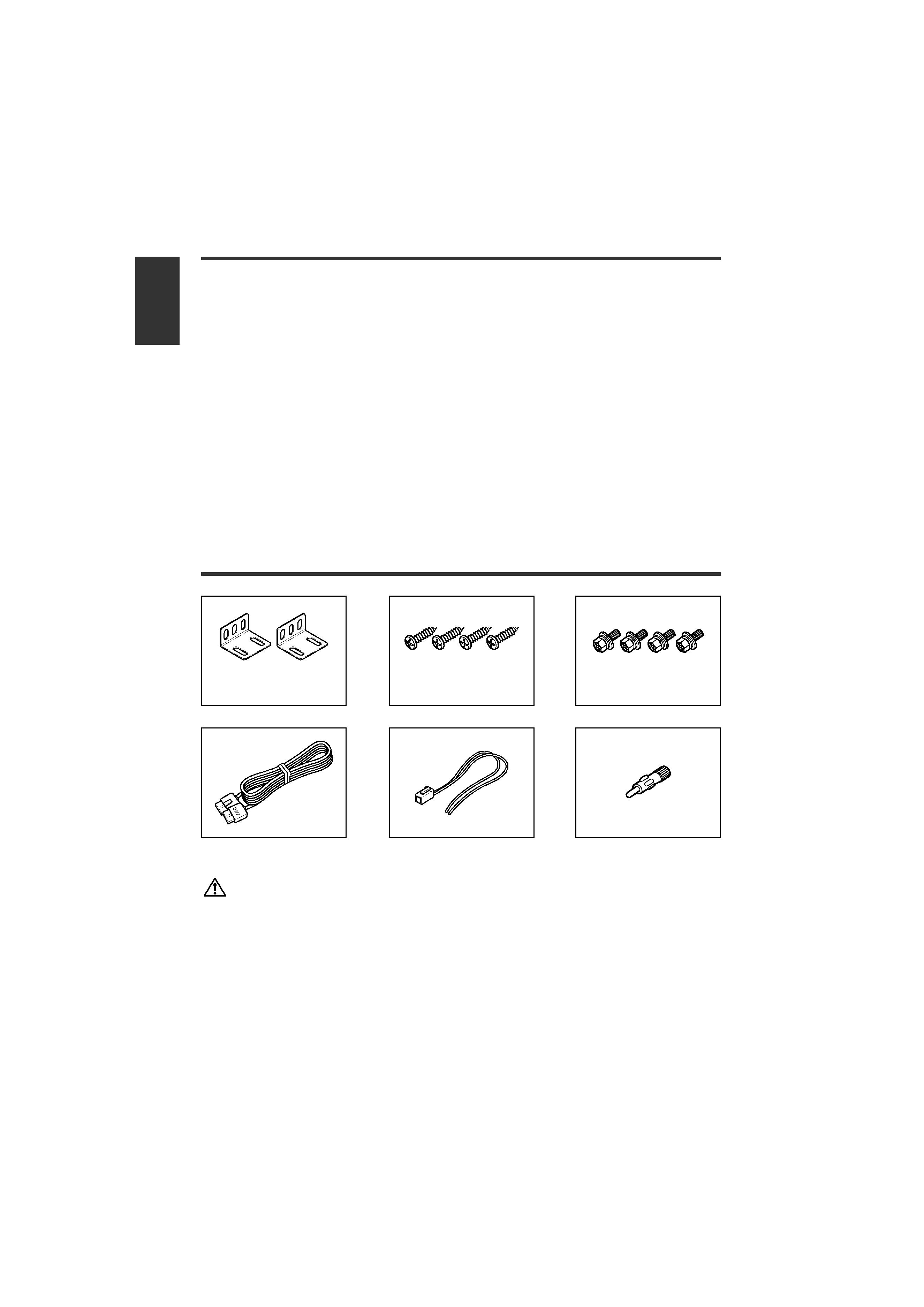
Accessories
The use of any accessories except for those provided might result in damage to the
unit. Make sure only to use the accessories shipped with the unit, as shown above.
English
2 English
C (M3x8 mm) ....4
B (ø4x16 mm) ....4
A ..........2
D ..........1
E ..........1
F ..........1
KNA-TM320_6L r2
03.7.25
9:52 AM
Page 2
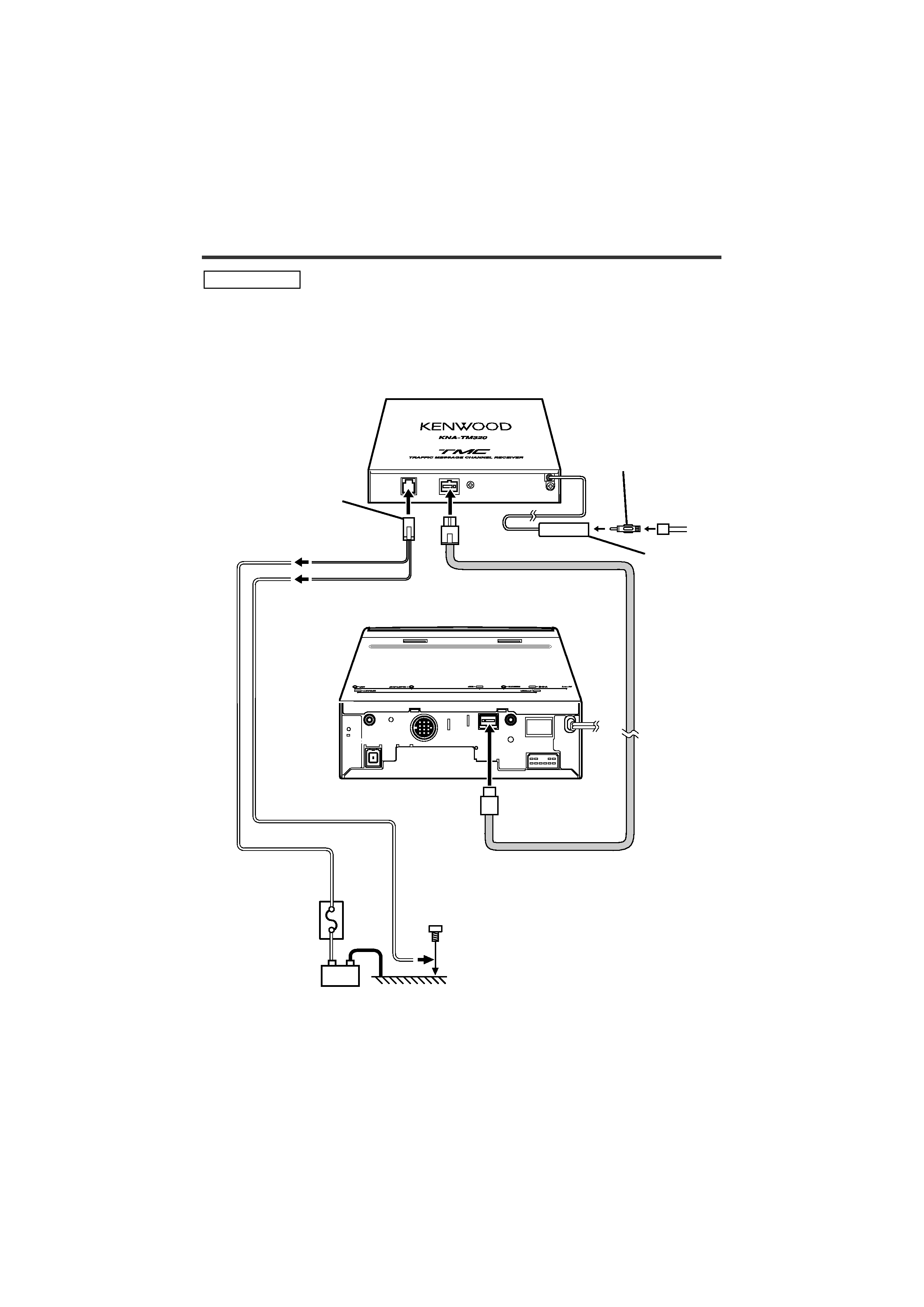
+-
TMC Receiver
Navigation Unit
Antenna Conversion
Adaptor (ISOJASO)
(Accessory F)
FM/AM
antenna input
Interface cable
(Accessory D)
Battery
Car fuse box
(Main fuse)
Ground cable (Black) -
(To car cassis)
TMC Receiver
Connection Cable
(Accessory E)
Antenna
Cord (ISO) 3
Battery cable
(Yellow)
English 3
Connection
If you connect the ignition wire (yellow) to the car chassis (ground), you may cause a short
circuit, that in turn may start a fire. Always connect these wire to the power source running
through the fuse box.
2WARNING
KNA-TM320_6L r2
03.7.25
9:52 AM
Page 3
English
4 English
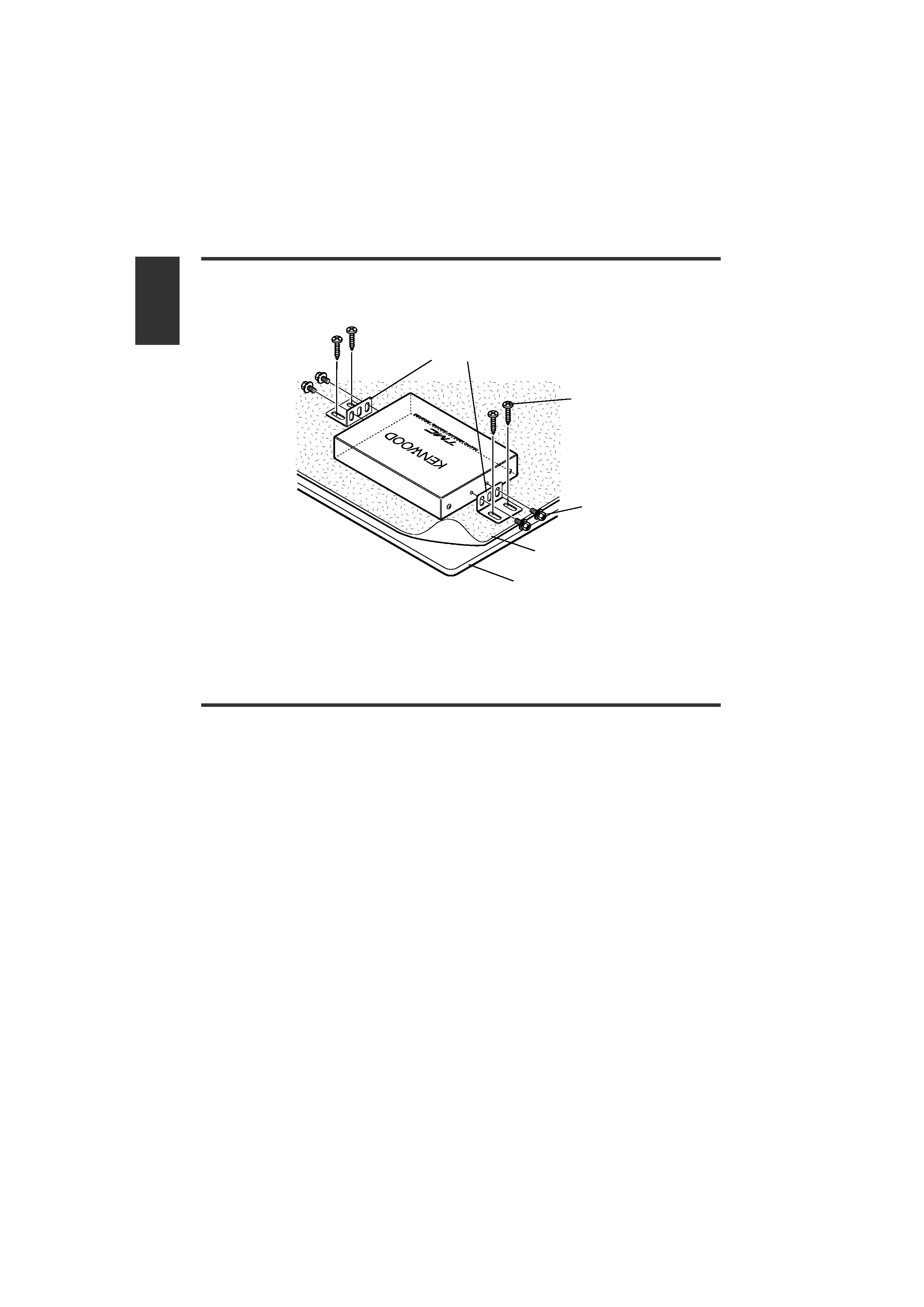
Installation
Installation using the self-tapping screws
Specifications
Specifications subject to change without notice.
TMC Receiver
Channel selection system..............................................................PLL freuency synthesizer system
Frequency range ....................................................................................................87.5 108.0 MHz
Frequency step ......................................................................................................................100 kHz
Antenna input............................................................................................................JASO connector
General
Operating Voltage ............................................................................................14.4 V DC (11 16 V)
Current Consumption ............................................................................................................300 mA
Dimensions ..........................................................................................140(W) x 25(H) x 100(D) mm
Operational temperature range ..................................................................................10°C to +55°C
Storage temperature range ........................................................................................30°C to +85°C
Weight ........................................................................................................................................340g
Accessory B
(ø4x16 mm)
Accessory C
(M3x8 mm)
Carpet
Accessory A
Board etc.
KNA-TM320_6L r2
03.7.25
9:52 AM
Page 4

KNA-TM320_6L r2
03.7.25
9:52 AM
Page 5