
KMF-X9000
POWER AMPLIFIER
INSTRUCTION MANUAL
B60-5097-08 01
KO (Y,E)
0103
2 EN
Introduction
Thank you for selecting our power amplifier as part of your high-fidelity system. We at KENWOOD are confident that your choice
will bring you years of rich listening pleasure. Please take the time to read through this booklet carefully. It will help you to obtain
the peak performance your power amplifier can deliver.
Features
Lucasfilm THX® Ultra Certification
THX® Ultra certification means that the KMF-X9000 meets
Lucasfilm's most stringent performance standards. This en-
sures superb sound quality and compatibility with other THX®-
certified products.
Operation Modes
The KMF-X9000 can be used in one of three different opera-
tion modes: 2-channel stereo, 2-channel mono, or Mono
(bridged, or BTL), so it can fit into almost any system configu-
ration and deliver all the power your speakers need.
Lucasfilm and THX are trademarks of Lucasfilm Ltd.
12 V Relay Power Control
The KMF-X9000 can be powered on and off by an external 12
volt trigger signal, so it can be installed in a remote location.
Before applying power
Caution: Read this page carefully to ensure safe operation.
Units are designed for operation as follows.
Europe and U.K. ....................... AC 230 V only
*Other countries ...................... AC 110-120 V/220 V-240 V switchable
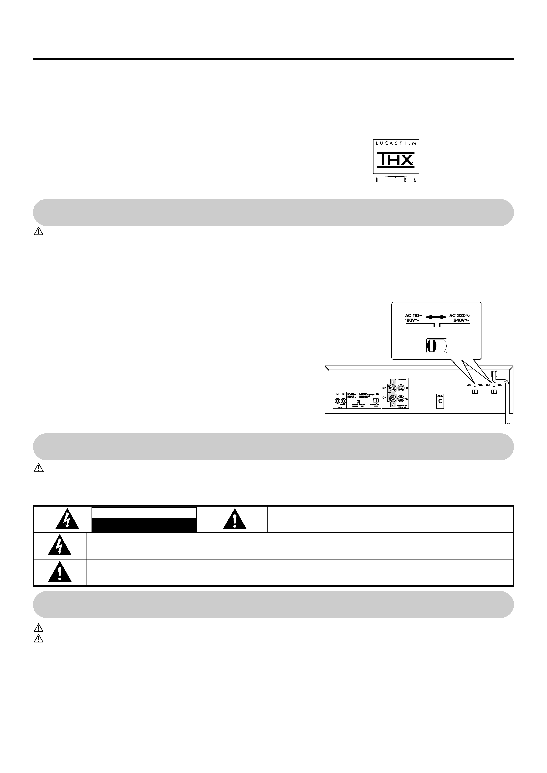
*AC voltage selection
The AC voltage selector switch on the rear panel is set to the voltage that prevails in the
area to which the unit is shipped. Before connecting the power cord to your AC outlet,
make sure that the setting position of this switch matches your line voltage. If not, move
the switch to match your line voltage with a screwdriver or similar tool.
Note:
Our warranty does not cover damage caused by excessive line
voltage due to improper setting of the voltage selector switch.
Contents
Mono (bridged, or BTL) configuration ........................ 5
2-Channel mono configuration ................................... 6
12 V Relay power control ......................................... 6
Controls and indicators ................................................ 7
In case of difficulty ......................................................... 7
Operation to reset .................................................... 7
Troubleshooting ......................................................... 7
Specifications ................................................ Back cover
Before applying power ............................................ 2
Safety precautions .................................................. 2
Unpacking ...................................................................... 3
Installation ...................................................................... 3
Notes on heat generation ......................................... 3
Connections .................................................................... 3
Connections of speaker cords ................................... 3
2-Channel stereo configuration .................................. 4
Caution: Read this page carefully to ensure safe operation.
WARNING: TO PREVENT FIRE OR ELECTRIC SHOCK, DO NOT EXPOSE THIS APPLIANCE TO
RAIN OR MOISTURE.
THE EXCLAMATION POINT WITHIN AN EQUILATERAL TRIANGLE IS INTENDED TO ALERT THE USER TO THE PRESENCE OF IMPOR-
TANT OPERATING AND MAINTENANCE (SERVICING) INSTRUCTIONS IN THE LITERATURE ACCOMPANYING THE APPLIANCE.
THE LIGHTNING FLASH WITH ARROWHEAD SYMBOL, WITHIN AN EQUILATERAL TRIANGLE, IS INTENDED TO ALERT THE USER
TO THE PRESENCE OF UNINSULATED "DANGEROUS VOLTAGE" WITHIN THE PRODUCT'S ENCLOSURE THAT MAY BE OF SUFFI-
CIENT MAGNITUDE TO CONSTITUTE A RISK OF ELECTRIC SHOCK TO PERSONS.
CAUTION: TO REDUCE THE RISK OF ELECTRIC SHOCK, DO NOT REMOVE
COVER (OR BACK). NO USER-SERVICEABLE PARTS INSIDE. REFER SER-
VICING TO QUALIFIED SERVICE PERSONNEL.
CAUTION
RISK OF ELECTRIC SHOCK
DO NOT OPEN
Safety precautions
3 EN
Installation
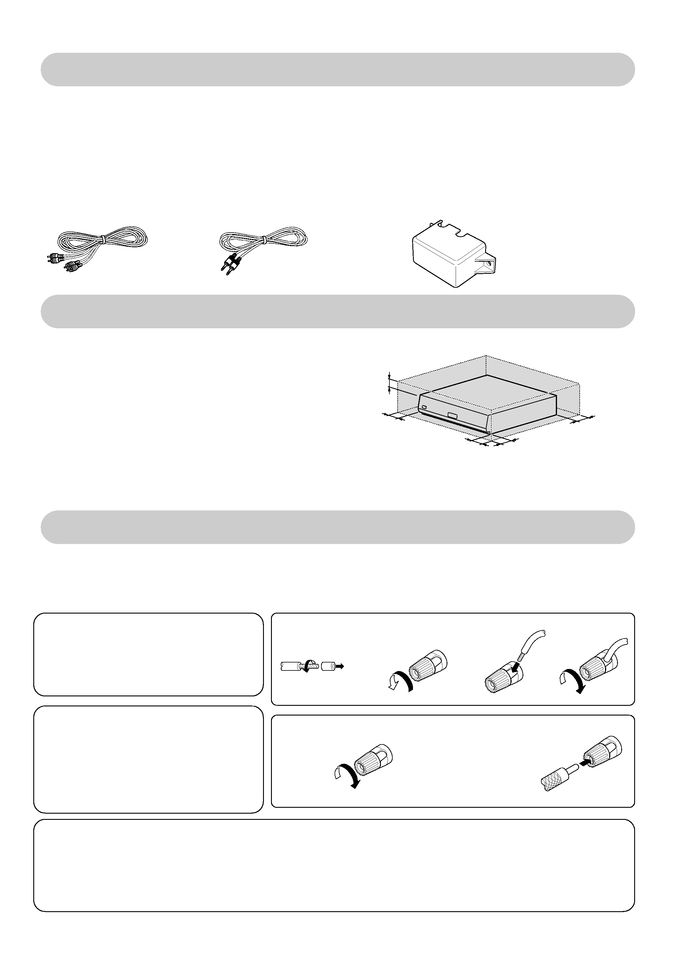
7Notes on heat generation
· This unit incorporates a ventilation fan to process heat gen-
erated during operation. As the fan starts to rotate automati-
cally when the internal temperature of this unit rises, avoid
installing or setting which may prevent ventilation of the unit.
* Leave clearance of more than 10 cm (4 in.) to the left and
right, more than 50 cm (20 in.) above and more than 10 cm
(4 in.) in front and rear of the unit. Also, do not close the
surroundings of the unit tightly when it is mounted on a rack.
· The ventilation fan of this unit has been designed to intake
external air into the unit. If curtain or a piece of paper is attracted by the air intake, the internal temperature will rise and protection
circuitry will be activated. In this case, the sound will not be output.
Connection of banana plugs (Except for some countries, like
Singapore, etc.)
1 Secure.
2 Insert.
Connections of speaker cords
1 Strip coating.
2 Loosen.
3 Insert.
4 Secure.
· Sound will not be heard if the speaker terminal is not fully secured.
Connections
Make connection as shown below. When connecting the related system components, refer also to the instruction manuals of the
related components. Do not plug in the power lead until all connections are completed.
7Connections of speaker cords
For U.S.A.
CAUTION:
If the unit is used in the U.S.A., please read the
supplement to the operating instruction entitled
"Connection of speaker cords".
Warning!
Particular attention must be given to making
good electrical contact at the amplifier-output
and speaker terminals.
Poor or loose connections can cause sparking
or burning at the terminals because of the very
high power that the amplifier can deliver.
CAUTIONS:
·
Connect all cords firmly. If connections are loose, there could be loss of sound or noise produced.
·
Never attempt to connect two or more speaker cords to a single speaker terminal.
·
Never short-circuit the + and - speaker cords.
·
If the left and right speakers are connected inversely or if the speaker cords are connected with reversed polarity, the sound
becomes unnatural with ambiguous acoustic image positioning. Be sure to connect the speakers and speaker cords correctly.
Unpacking
Unpack the unit carefully and make sure that all accessories
are put aside so they will not be lost.
Examine the unit for any possibility of shipping damage. If your
unit is damaged or fails to operate, notify your dealer immedi-
ately. If your unit was shipped to you directly, notify the ship-
ping company without delay. Only the consignee (the person
or company receiving the unit) can file a claim against the car-
rier for shipping damage.
We recommend that you retain the original carton and packing
materials for use should you transport or ship the unit in the
future.
Accessories
Audio cord (1)
Stereo mini-plug cord (1)
Speaker terminal cover (1) (Except for Europe)
More than
10 cm (4 in.)
More than
10 cm (4 in.)
More than
10 cm (4 in.)
More than
50 cm (20 in.)
More than
10 cm (4 in.)
4 EN
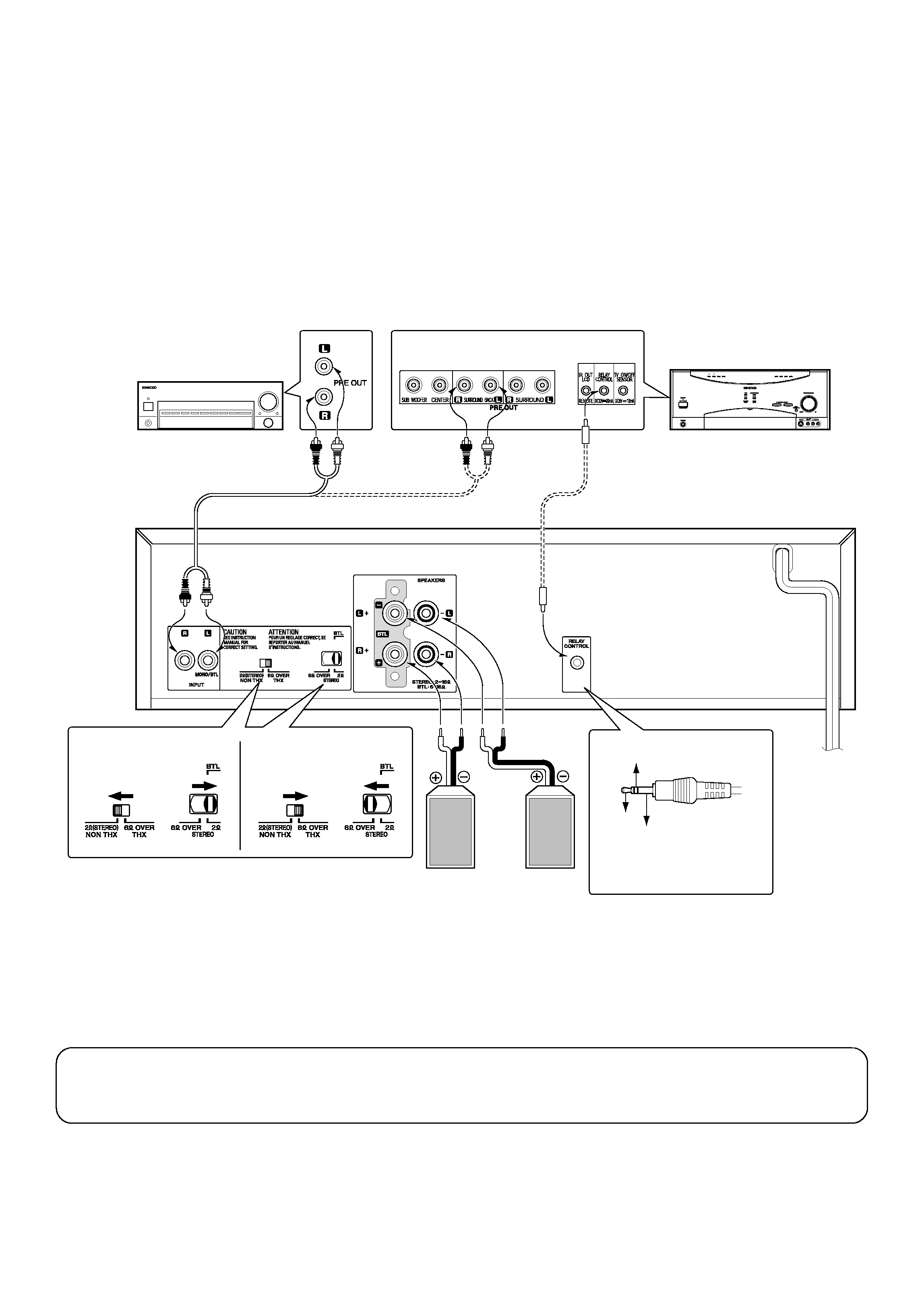
72-Channel stereo configuration
This is the `standard' stereo operation mode, with the amplifier driving 2 speakers in stereo (such as the Surround Back Left and
Surround Back Right speakers in a THX Surround EX® home theater system). The amplifier delivers its rated stereo power output
into each speaker.
1 Make sure that the KMF-X9000's power cord is unplugged from the wall outlet before making any connections.
2 According to the speakers to be used, set the speaker impedance selector switch as follows:
· For 2
speakers: Set the 2 (STEREO)/6 OVER switch to 2 (STEREO) and 6 OVER/2 switch to 2.
· For 6-16
speakers: Set the 2 (STEREO)/6 OVER switch to 6 OVER and 6 OVER/2 switch to 6 OVER.
3 Connect the amplifier as shown in the diagram.
CLIP
INDICATOR
CD 2 / TAPE 2
MONITOR
SURROUND
BACK
96kfs
DISCRETE 6.1
MATRIX 6.1
NEO : 6
PRO LOGIC
DTS-ES
* If you connect more than one pair of speakers to the KMF-X9000, move the 2
(STEREO)/6 OVER (THX) switch to the 2
(STEREO) position. The amplifier's performance is not THX®-certified when the switch is set in the 2
(STEREO) position.
Now you can plug the power cord of this unit into the AC outlet!
CAUTION:
Before reconnecting a speaker cord or switching a selector switch, turn OFF the power and unplug the power
cord to avoid malfunctions or damage to the unit.
Preamplifier
Audio cord (supplied)
To wall AC outlet
Speakers
(2
-16)
* In the case of 2
ON : +12 V
OFF : OPEN (or GND)
NC
GND
KRF-X9995D
For RELAY CONTROL connec-
tion to KRF-X9995D or other
compatible unit, see page 6.
Left
(L SURROUND
BACK)
Right
(R SURROUND
BACK)
In the case of 6
Stereo mini-plug cord (supplied)
For 12 V RELAY CONTROL, see page 6.
5 EN
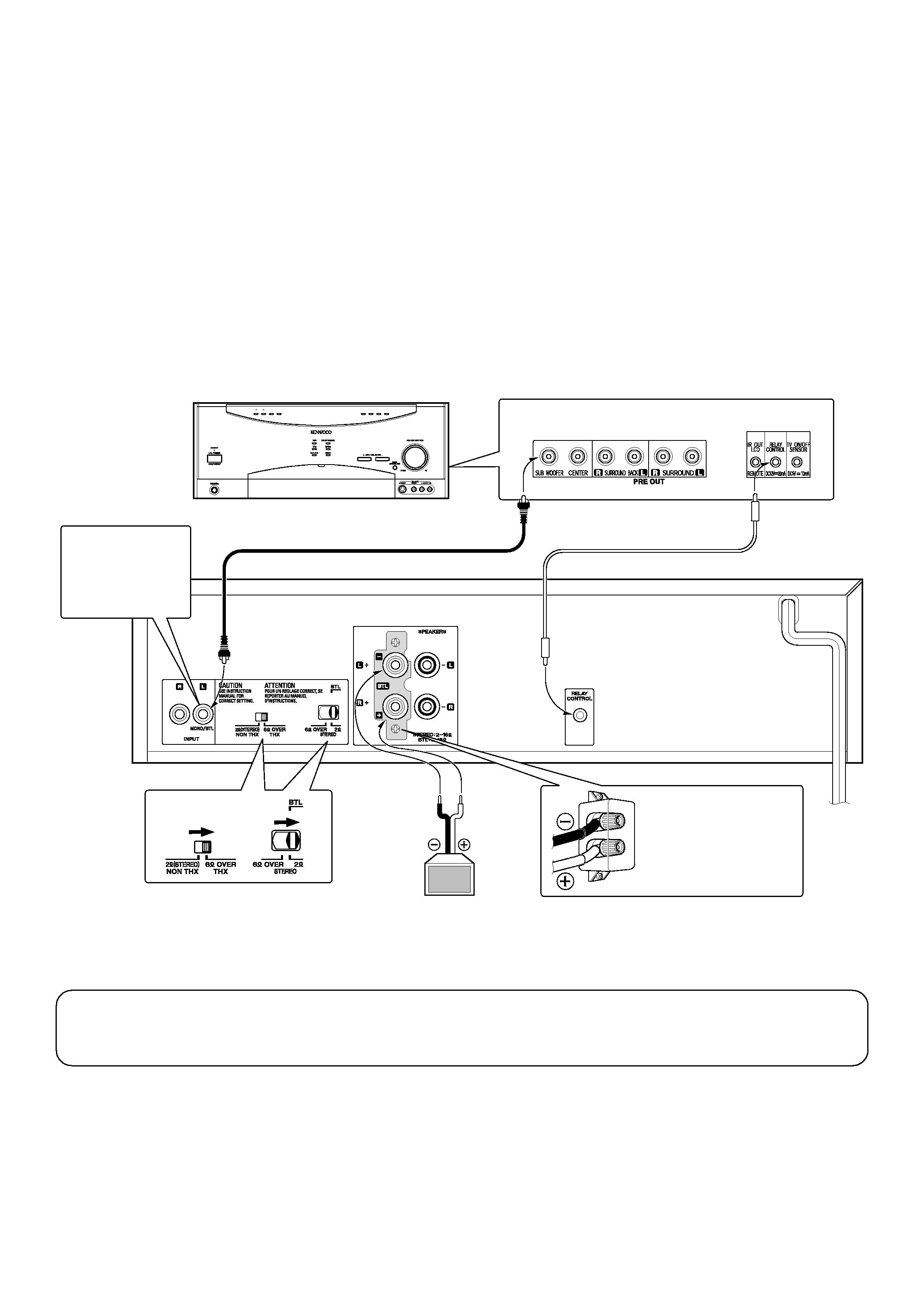
7Mono (bridged, or BTL) configuration
In this configuration, the KMF-X9000's two individual channels operate together to drive a single speaker (such as a subwoofer) in
mono. This allows the amplifier to deliver more than double the power of one of its channels to the speaker.
1 Make sure that the KMF-X9000's power cord is unplugged from the wall outlet before making any connections.
2 According to the speakers to be used, set the speaker impedance selector switch as follows:
· For 6-16
speakers: Set the 2 (STEREO)/6 OVER switch to 6 OVER and 6 OVER/2 switch to 2.
3 Connect the amplifier as shown in the diagram.
· Make sure to connect the audio input cable to the MONO/BTL input.
Except for Europe
Note:
Since bridged operation produces enough output power to pose a small risk of electrical shock from the speaker termi-
nals, please attach the terminal cover as shown in the diagram below:
CLIP
INDICATOR
CD 2 / TAPE 2
MONITOR
SURROUND
BACK
96kfs
DISCRETE 6.1
MATRIX 6.1
NEO : 6
PRO LOGIC
DTS-ES
Now you can plug the power cord of this unit into the AC outlet!
CAUTION:
Before reconnecting a speaker cord or switching a selector switch, turn OFF the power and unplug the power
cord to avoid malfunctions or damage to the unit.
Except for Europe
Mount the supplied
speaker terminal cover
using the two screws that
are attached to the unit.
KRF-X9995D
When a monaural
pre-out signal is to
be connected, be
sure to connect it to
the MONO/BTL
terminal.
Audio cord (not supplied)
Stereo mini-plug cord (supplied)
To wall AC
outlet
Subwoofers
(6
-16)
For 12 V RELAY CONTROL, see page 6.