© 2001-10 PRINTED IN JAPAN
B51-8596-00 (N) 1422
MODEM GPS RECEIVER / MODEM GPS CONTROLLER
KGP-2A/2B
SERVICE MANUAL
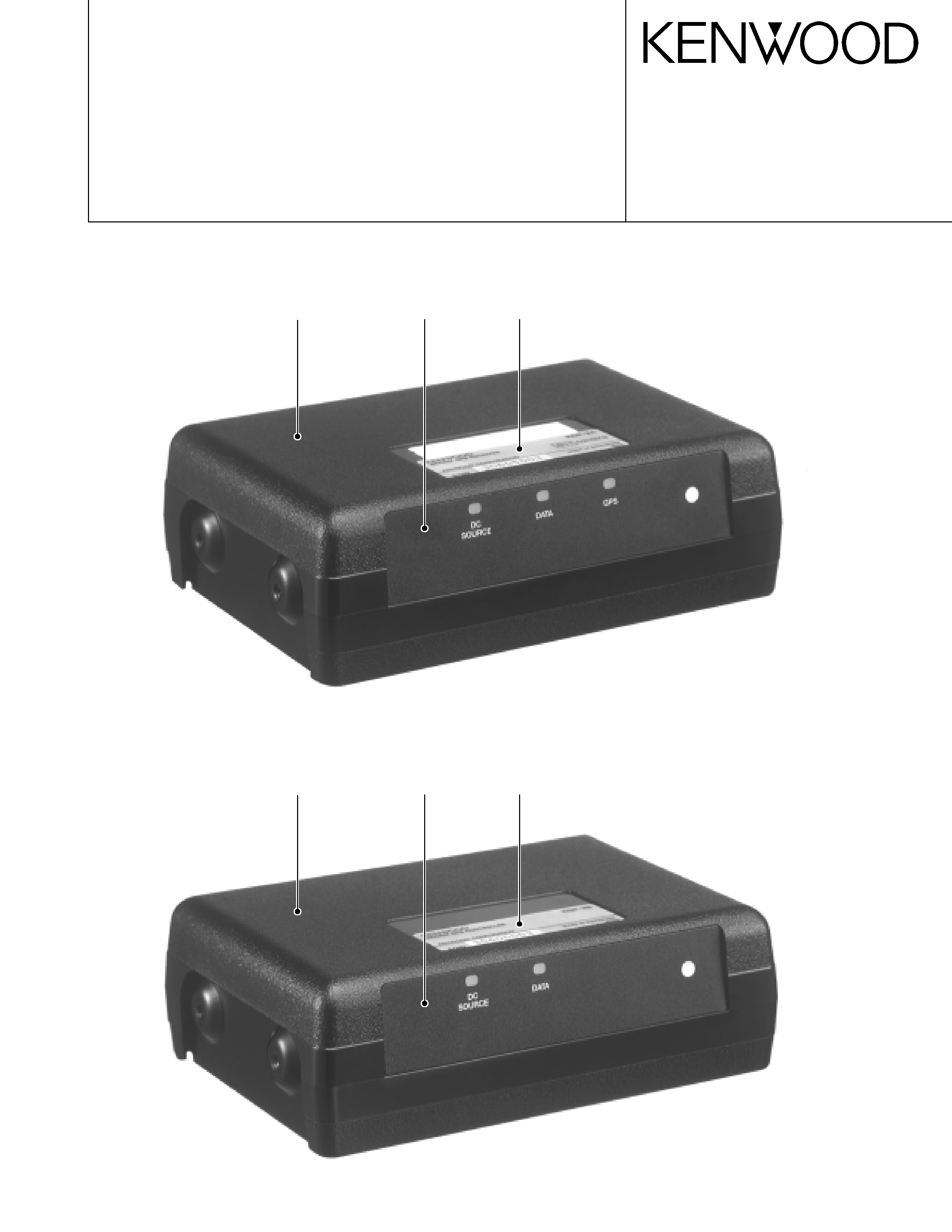
Cabinet
(A02-3660-11)
Dressing Panel
(A21-1632-14)
Model name plate
(B72-1963-14)
Cabinet
(A02-3660-11)
Dressing Panel
(A21-1633-14)
Model name plate
(B72-1964-04)
KGP-2A
KGP-2B
2
KGP-2A/2B
INSTALLATION
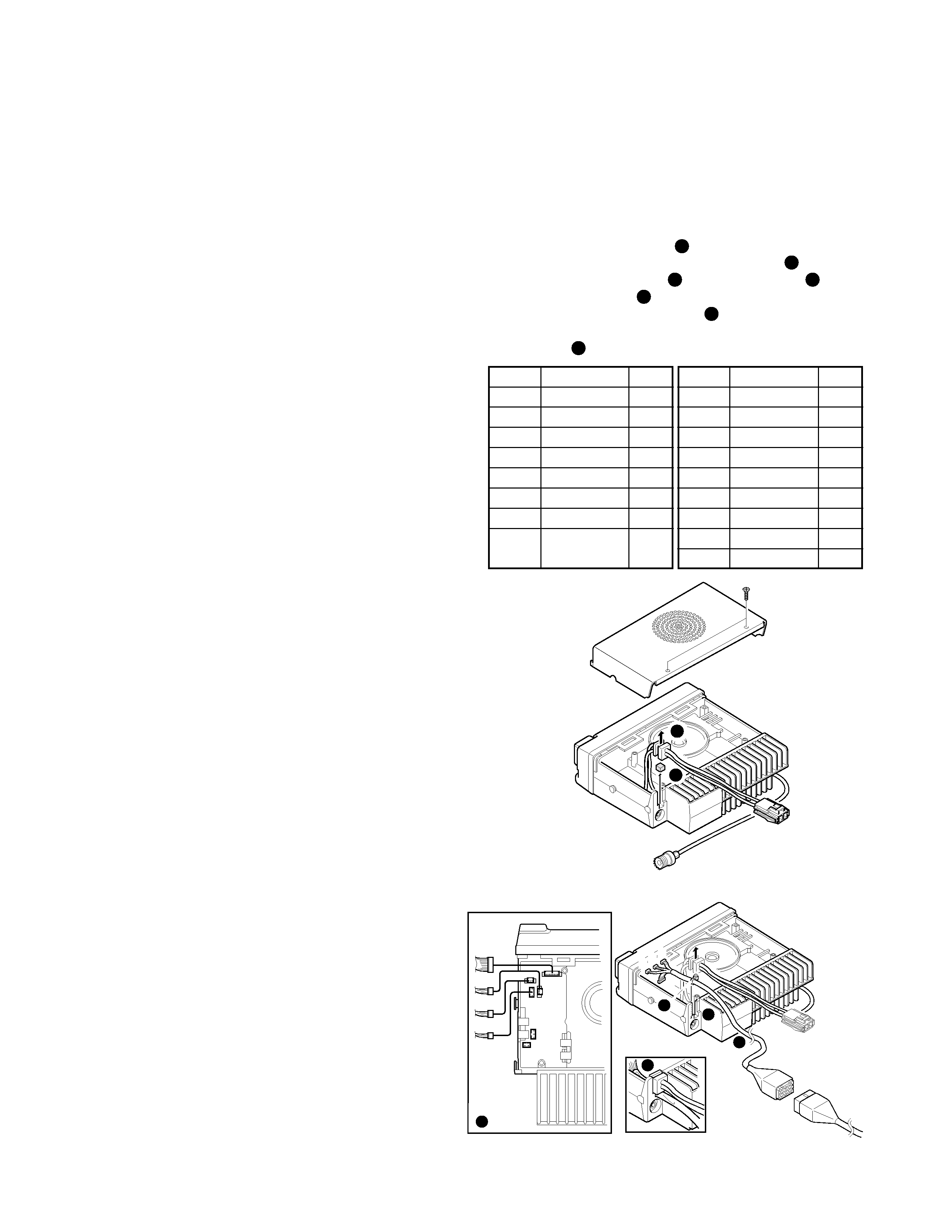
TK-780/880/980/981 Series (TK-*80 Series)
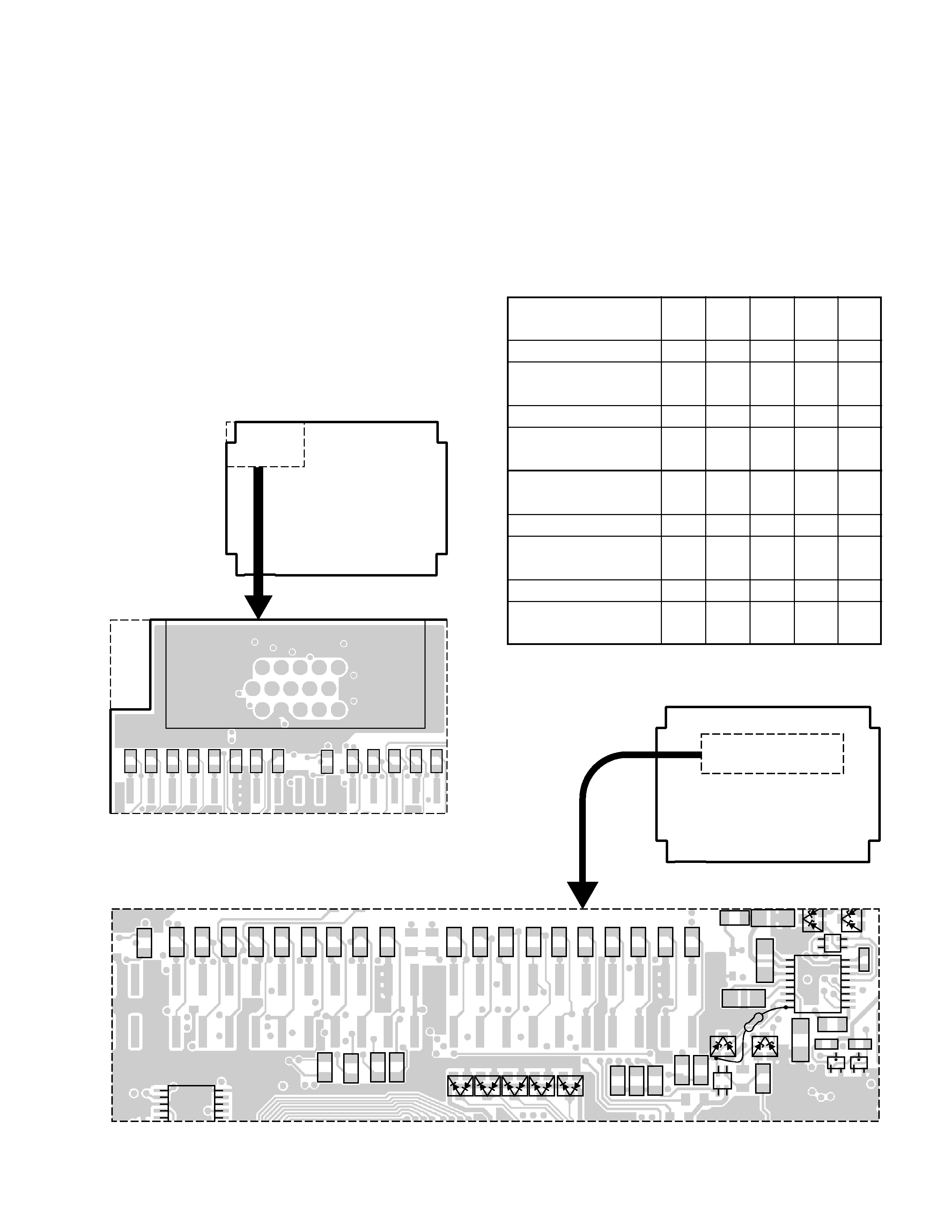
s Installing the KCT-34 in the Transceiver
1. Remove the upper cover from the transceiver.
2. Lift the DC cord bushing ( 1 ) from the chassis.
3. Remove the pad as shown in the Figure 1 ( 2 ).
4. Insert the KCT-34 cable ( 3 ) into the chassis ( 4 ). The
wire harness band ( 5 ) must be inside the chassis.
5. Replace the DC cord bushing ( 6 ).
6. Connect the KCT-34 to the TX-RX unit (A/2) as shown in
Figure 2 ( 7 ).
Fig. 1
1
2
D
C
B
A
1
3
13
15
KGP-2A/2B or
through KCT-36
extension cable.
KCT-34
CN1
CN2
CN4
CN3
A
B
C
D
3
4
6
7
5
Fig. 2
Connector
Wire Color
Pin No.
A-1
Brown
4
A-2
NC
A-3
NC
A-4
Orange
5
A-5
Gray
10
A-6
NC
A-7
Yellow
6
A-8
Blue
8
CONTENTS / INSTALLATION
Connector
Wire Color
Pin No.
B-1
NC
B-2
White
11
B-3
Green
7
C-1
Purple
9
C-2
Light blue
14
C-3
Light green
15
D-1
NC
D-2
Black
3
D-3
Red
1
CONTENTS
INSTALLATION ......................................... 2
REALIGNMENT ......................................... 3
MODIFICATION ......................................... 5
DISASSEMBLY FOR REPAIR ................... 6
ADJUSTMENT .......................................... 6
CIRCUIT DESCRIPTION ............................ 8
DESCRIPTION OF COMPONENTS ........ 10
SEMICONDUCTOR DATA ...................... 11
PARTS LIST ............................................. 12
EXPLODED VIEW .................................... 19
PACKING ................................................. 20
PC BOARD VIEWS
CONTROL UNIT (X53-3980-20) .......... 21
CONTROL UNIT (X53-3980-21) .......... 25
SCHEMATIC DIAGRAM .......................... 29
BLOCK DIAGRAM ................................... 33
LEVEL DIAGRAM .................................... 37
TERMINAL FUNCTION ........................... 38
SPECIFICATIONS .................................... 39
3
KGP-2A/2B
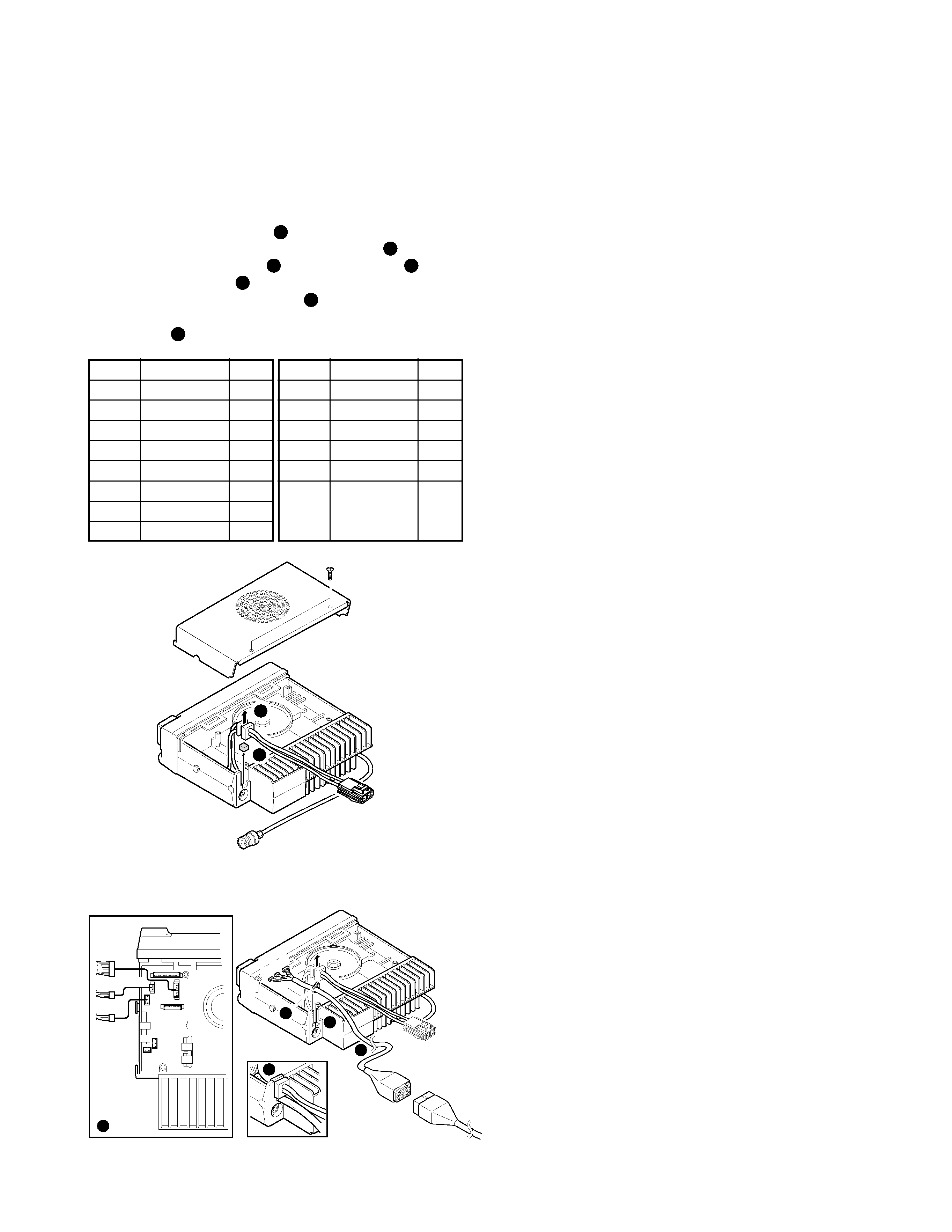
TK-760G/762G/860G/862G/768G/868G Series
(TK-*60G Series)
s Installing the KCT-35 in the Transceiver
1. Remove the upper cover from the transceiver.
2. Lift the DC cord bushing ( 1 ) from the chassis.
3. Remove the pad as shown in the Figure 3 ( 2 ).
4. Insert the KCT-35 cable ( 3 ) into the chassis ( 4 ). The
wire harness band ( 5 ) must be inside the chassis.
5. Replace the DC cord bushing ( 6 ).
6. Connect the KCT-35 to the TX-RX unit (A/2) as shown in
Figure 4 ( 7 ).
Fig. 3
1
2
Fig. 4
A
B
C
3
4
6
7
5
KGP-2A/2B or
through KCT-36
extension cable.
KCT-35
1
13
15
3
CN5
A
B
C
CN4
CN3
Connector
Wire Color
Pin No.
A-1
Brown
4
A-2
Green
7
A-3
NC
A-4
Orange
5
A-5
NC
A-6
NC
A-7
Yellow
6
A-8
Blue
8
Connector
Wire Color
Pin No.
B-1
Gray
10
B-2
White
11
B-3
Purple
9
C-1
NC
C-2
Black
3
C-3
Red
1
INSTALLATION / REALIGNMENT
REALIGNMENT
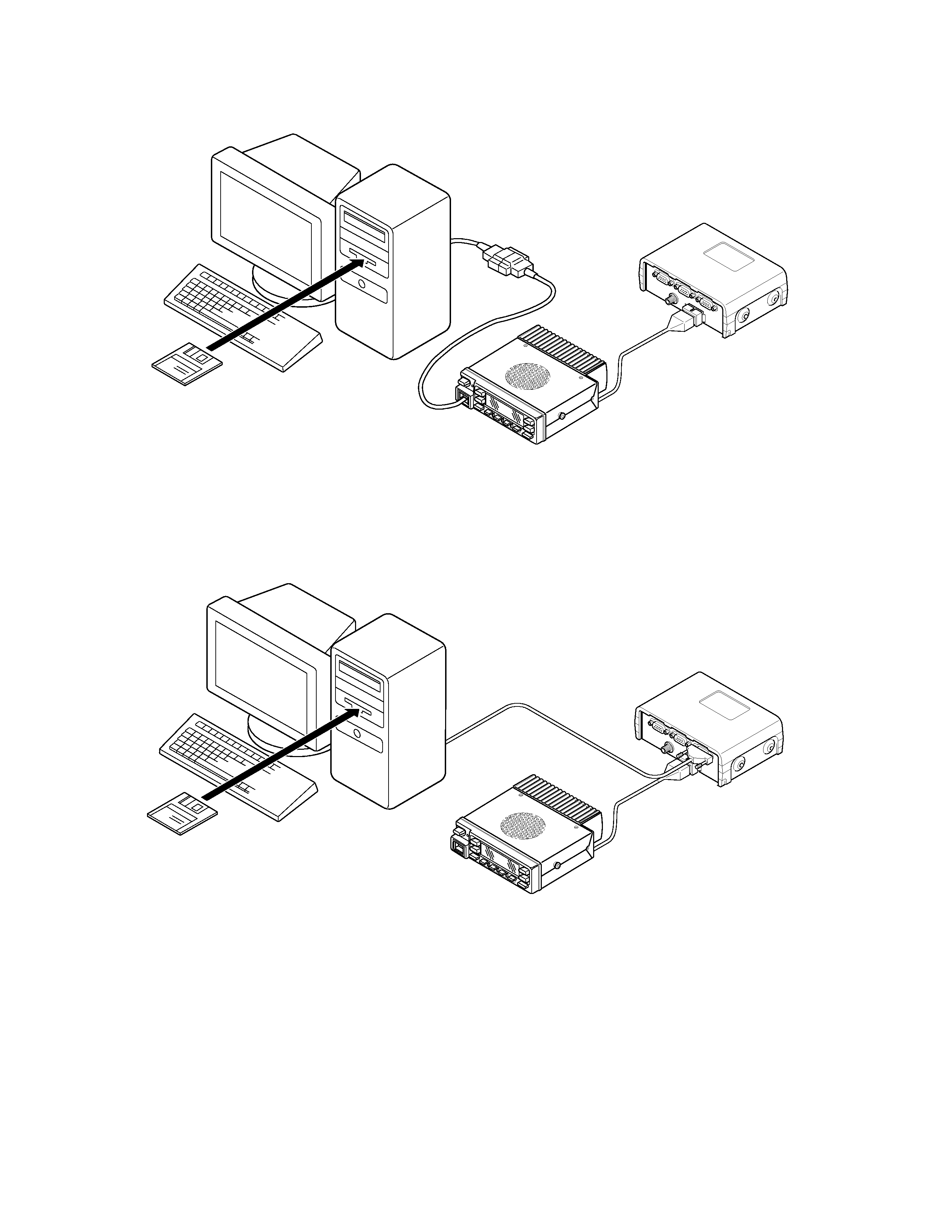
Transceiver Setting
When the KGP-2A/2B is connected to a transceiver, the
transceiver functions must be set. The transceiver FPU is
used to make this setting.
For a connection method, see Figure 1.
s TK-*80 Series Setting Method
1. Setting with KPG-49D (K and M markets FPU)
1) Select "Optional Features" from "Edit" on the menu bar
and change Com2 (Internal Port) from "[None]" to "[AUX
Hook/PTT]".
2. Setting with KPG-60D (E markets FPU)
1) Select "Extended Function" from "Edit" on the menu
bar and change Com2 from "[None]" to "[AUX Hook/
PTT]".
s TK-*60G Series Setting Method
Use the KPG-56D as the FPU.
1) Select "Key assignment" from "Edit" on the menu bar,
and set "Foot Switch" to "[None]".
2) Select "Optional Features" from "Edit" on the menu bar
and change "ACC Hook/DTC" from "[ACC Hook]" to
"[DTC]".
Note :
Applicable only for S/No. 302XXXXX or later.
KGP-2A/2B Setting
After programming the transceiver, you need to config-
ure the KGP-2A/2B. Using the FPU (KPG-73D), you can con-
figure the KGP-2A/2B .
Using a cross-wired serial cable (KGP-2A/2B side : D-sub
9- pin female) as shown in Figure 2, plug one connector into
the RS-232C (COM) port of your PC and the other end to the
ACC1 connector on the rear panel of the KGP-2A/2B.
s KGP-2A/2B Setting Method
1) Create a data file using the FPU (KPG-73D).
2) After configuring the KGP-2A/2B to the Programming
Menu mode, upload the data file to the KGP-2A/2B.
For detailed instructions, refer to the Help file included in
the FPU.
To set the KGP-2A/2B in the Programming Menu mode,
refer to "Start the Programming Menu mode" on page 6.
4
KGP-2A/2B
REALIGNMENT
Fig. 1
Fig. 2
IBM-PC
KPG-46
Transceiver
KGP-2A/2B
KPG-49D or KPG-60D : TK-*80
KPG-56D : TK-*60G
IBM-PC
KPG-73D : KGP-2A/2B
KGP-2A/2B
Transceiver
Cross-wired serial cable
(KGP-2A/2B side :
D-sub 9-pin female)
5
KGP-2A/2B
MODIFICATION
Connecting a Separate Microphone for
Emergency Mode (KGP-2A only)
If you apply the modification as described below, you can
connect a separate microphone to the KGP-2A in place of
the transceiver's microphone for Emergency mode. The
base station application software which can send out a cor-
responding command is required for the change of a micro-
phone which operates in the time of emergency transmis-
sion.
s Modification
1. Remove R171 (0
).
2. Remove R172 (0
).
3. Add 0
(R92-0670-05) to the $R17 location.
4. Add 0
(R92-0670-05) to the $R18 location.
$R17
$R18
R171
R172
J1 ACC3
11
1
5
6
10
15
Add
Remove
CONTROL UNIT
(X53-3980-20)
Component side view
J1 (ACC3) Pin 5 : Microphone input
J1 (ACC3) Pin 6 : Microphone ground (GND)
R186
R191
R162
R169
$R190
Lead resistor
$R221
$R192
$R184
$R185
CONTROL UNIT
(X53-3980-20)
Component side view
Since 5V DC goes through R55 (56k
) and then it is sup-
plied to the microphone input, an electric condenser-type
microphone can be connected to this terminal.
You can also adjust the microphone sensitivity by chang-
ing the R206 (560
) constant between 330 and approxi-
mately 1k
. The microphone pre-emphasis and IDC are car-
ried out by the DSP IC (IC29).
Modification Setting for DGPS (KGP-2A only)
Input method of
$R192
R186 $R184 $R185
R191
DGPS signal
(0
)(0)(0)(0)(0)
5V input from ACC2
Yes
No
Yes
No
No
RS-232C level input
Yes
No
Yes
No
Yes
from ACC2
5V input from ACC3
Yes
No
No
Yes
No
RS-232C level input
Yes
No
No
Yes
Yes
from ACC3
Input method of
$R190 $R221 R162
R169
DGPS signal
(0
)(0)(0)(0)
5V input from ACC2
No
No
No
N/A
RS-232C level input
Yes
Yes
No
N/A
from ACC2
5V input from ACC3
No
No
N/A
No
RS-232C level input
Yes
Yes
N/A
No
from ACC3