
©B64-1779-00 (W)
KDS-P900
INSTRUCTION MANUAL
PROCESSEUR SURROUND DVD à 5.1 canaux
MODE D'EMPLOI
5.1ch DVD SURROUND PROCESSOR
5.1 Kan. DVD-SURROUND-PROZESSOR
BEDIENUNGSANLEITUNG
5.1 kan DVD-SURROUNDPROCESSOR
GEBRUIKSAANWIJZING
5.1 canale DVD SURROUND PROCESSOR
ISTRUZIONI PER L'USO
PROCESADOR SURROUND DVD de 5.1 canales
MANUAL DE INSTRUCCIONES
5.1 DVD
5.1 DVD
2-English
Installation
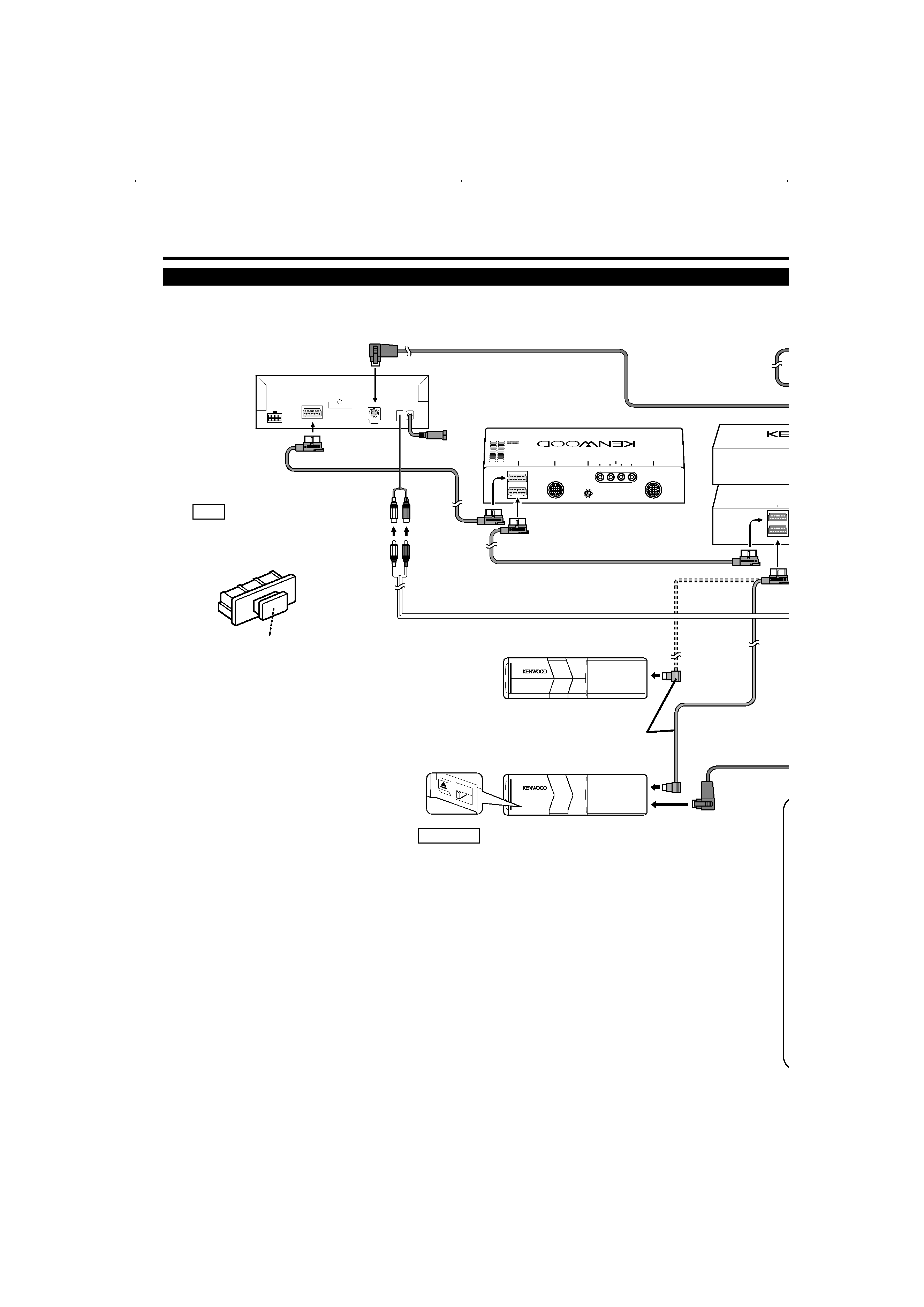
Connecting Cables to Terminals
TONA
V .I/F
TO
ANTENNA
TO5L
I/F
TOMZ-B
US
TOMONIT
OR
TOMZ-BUS
"1"
}
1-CH-2
M 4
DVD player unit
Connection cable (5.5m:Accessory q)
Optical cable (5.5m:Accessory r)
Receiver unit (front side)
MZ-BUS Disc Changer
C929
Put the protection caps removed
from the unit into the unused
terminals in the KDS-P900.
NOTE
Protection cap
DVD player unit & Receiver unit:
KVT-910DVD/920DVD/930DVD/940DVD/960DVD
Connection cable (Provided with the disc changer)
When connecting the C929 optical cable, be
sure to set the selector switch to 1.
2CAUTION
KDS-P900
02.12.16
9:30 AM
Page 2
English
-3
FM /AM
ANTENNA
AV INPUT
AV INPUT
L
R
L
R
1
2
VIDEO
VIDEO
FRONT
REAR
PREOUT
NON-FAD
AV OUTPUT
POWER
TO MONITOR UNIT
L
R
L
R
VIDEO
L
L
L
R
R
R
DIGITAL IN
CD-CH 1
DIGITAL IN
TV/DVD
REAR
R
REAR
L
AUDIOIN
R
AUDIOIN
L
FRONT
R
FRONT
L
CENTER
SUBW
T
REAR
R
REAR
L
AUDIOIN
R
AUDIOIN
L
FRONT
R
FRONT
L
CENTER
SUBW
30R
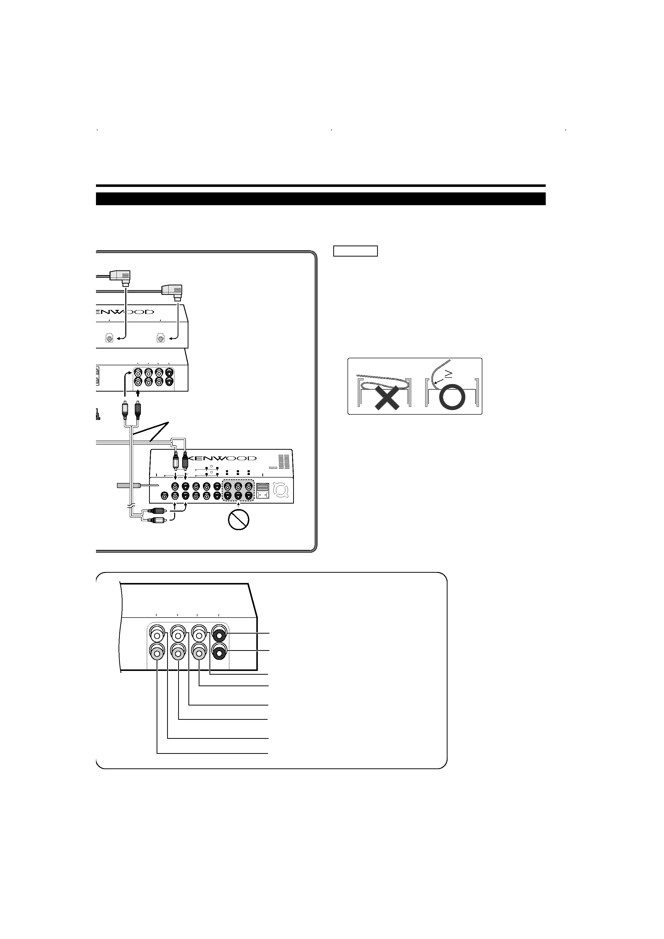
Subwoofer preout
Center Speaker preout
Front left output (white)
Front right output (red)
Rear left output (white)
Rear right output (red)
Left input (white)
Right input (red)
KDS-P900
(rear side)
(front side)
Receiver unit (rear side)
When handling an optical cable for wiring, use
care not to exceed the minimum cable bend
radius of 30 mm.
If you exceed the minimum bend limit, optical
fibers within the optical cable may be damaged.
When installing the DVD player unit on the
vehicle, ensure that the optical cable is not
stuck between the DVD player unit and vehicle
parts.
2CAUTION
Optical cable (Provided with the C929)
Audio cable
(Commercially available part)
KDS-P900
02.12.16
9:30 AM
Page 3
4-English
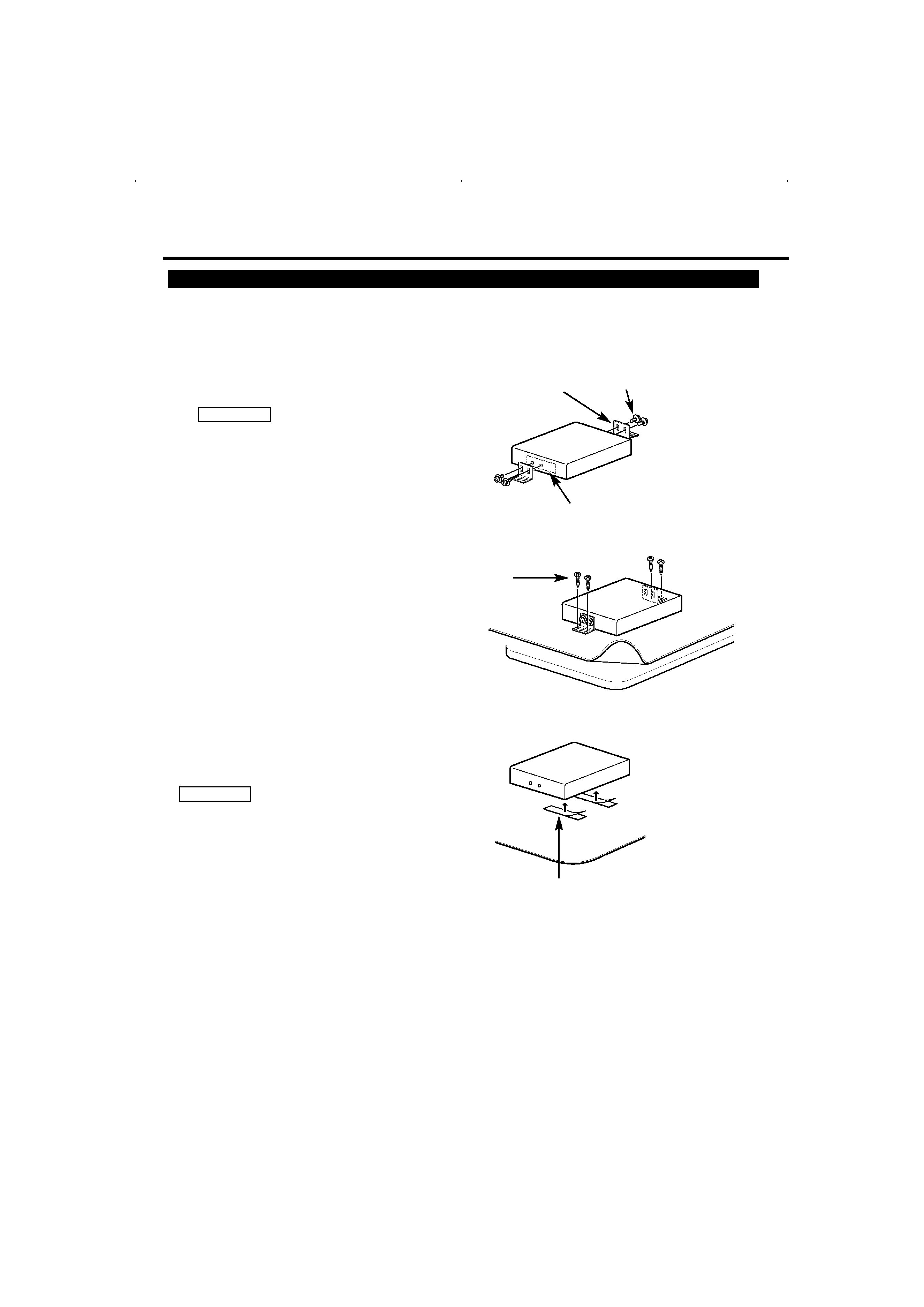
Securing to audio board
Remove the caution sticker and fasten the
installation brackets on the both sides of the
KDS-P900 using the sems screws (M4 x 8
mm).
1
;;;;;;
;;;;;;
Peel the protective strips off of the velcro strips,
attach them to the bottom of the hideaway unit,
and secure to the pile carpet.
Please do not install the unit near the
dashboard, the rear tray, or other important
components. Doing so could lead to injury or
accident should the unit come off due to a
shock and strike a person or an important
component.
Tapping screws should be used for mounting.
(Attachment with velcro strips, although easy,
can come off with a shock.)
2CAUTION
Sems bolts
(M4X8mm)
(Accessorye)
Tapping screw
(ø4X16mm)
(Accessoryt)
Installation
brackets
(Accessoryw)
Installation
Installation
Use the tapping screw (ø4X16mm) to secure
the hideaway unit to the audio board.
2
Securing to pile carpet
;;;;
;;;;
;;;;
Velcro strips
(Accessoryy)
Caution sticker
Use the supplied screws for installing the
KDS-P900. Using any other screw may
cause the equipment to improperly
function.
2CAUTION
KDS-P900
02.12.16
9:30 AM
Page 4
English
-5
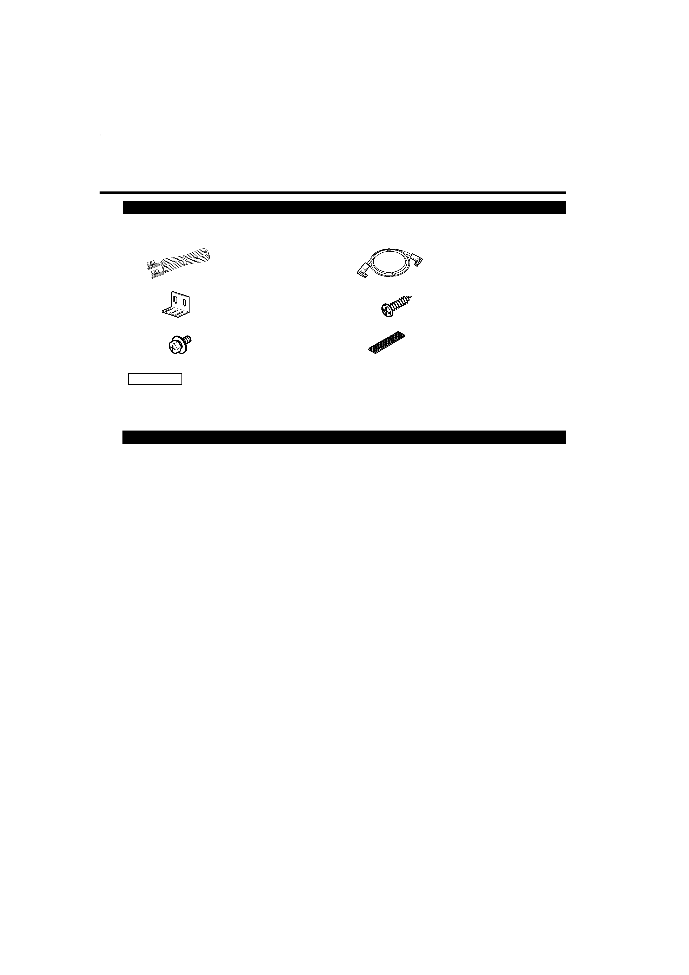
The use of any accessories except for those provided might result in damage to the unit. Make sure
only to use the accessories shipped with the unit, as shown above.
2CAUTION
Accessories
.........1
q
.........2
w
.........4
e
External view
......... Number of items
.........1
r
External view
......... Number of items
.........4
t
.........2
y
Specification
DSP section
D/A Converter ...............................................................................................................................................24 Bit
A/D Converter ...............................................................................................................................................24 Bit
Decorder ....................................................................................Linear PCM / Dolby prologic / Dolby digital / DTS
Equalizer
4BAND Parametric equalizer
BAND1 frequency : ...........................................60/80/100/120/160/200/250 Hz
BAND2 frequency : ................................................315/400/500/630/800/1K Hz
BAND3 frequency : .........................................1.25K/1.6K/2K/2.5K/3.15K/4K Hz
BAND4 frequency : .............................................5K/6.3K/8K/10K/12.5K/16K Hz
Gain
...........................................................................................................................................................±9 dB
Q control .......................................................................................................................................0.25/0.5/1.0/2.0
Crossover
Highpassfilter frequency :.....................................................................THR/30/60/90/120/150/180/250 Hz
Slope :....................................................................................................................12/18/24 dB
Lowpassfilter frequency : .............................................................................30/60/90/120/150/180/250 Hz
Slope :....................................................................................................................12/18/24 dB
Time alignment
(0.15mSTEP).................................................................................................................................0 3.0 m
(0.5ft STEP) .................................................................................................................................0 10.0 ft
(0.3mSTEP)................................................................................................................................3.0 6.0 m
(1.0ft STEP) ............................................................................................................................10.0 20.0 ft
Channel level ..............................................................................................................................................±10 d
B
Audio section
Preout level (V) ..................................................................................................................................4.5 V / 10 k
Preout impedance(
) ................................................................................................................................. 600
External audio max input level ..............................................................................................................1 V / 22 k
S/N Ratio (dB)..............................................................................................................................................100 dB
Harmonic Distortion
(20 kHz LPF , 1kHz)..........................................................................................................................0.01 %
Frequency Response ......................................................................................................................10 Hz 24 kHz
General
Installation Size (W x H x D) ....................................................................................................208 x 40 x 163 mm
(8-3/16 x 1-9/16 x 6-7/16 in.)
Weight ............................................................................................................................................2.0 lbs (0.9 kg)
Specifications subject to change without notice.
KDS-P900
02.12.16
9:30 AM
Page 5