© 2002-12 PRINTED IN JAPAN
B53-0014-00 (N) 1874
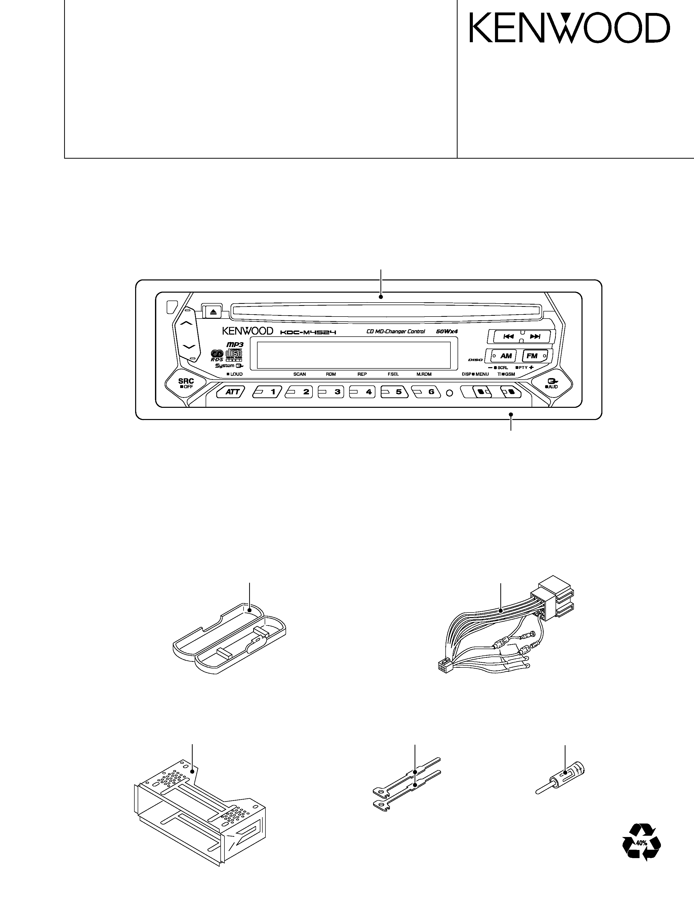
CD RECEIVER
KDC-M4524/G/Y/GY
SERVICE MANUAL
Panel assy
(A64-2879-02): KDC-M4524 /Y
(A64-2882-02): KDC-M4524G /GY
Escutcheon
(B07-3001-02)
Mounting hardware assy
(J21-9716-03)
Plastic cabinet assy
(A02-1486-13)
DC cord
(E30-4790-05)
Lever
(D10-4589-04)
Antena adaptor
(T90-0523-05)
2
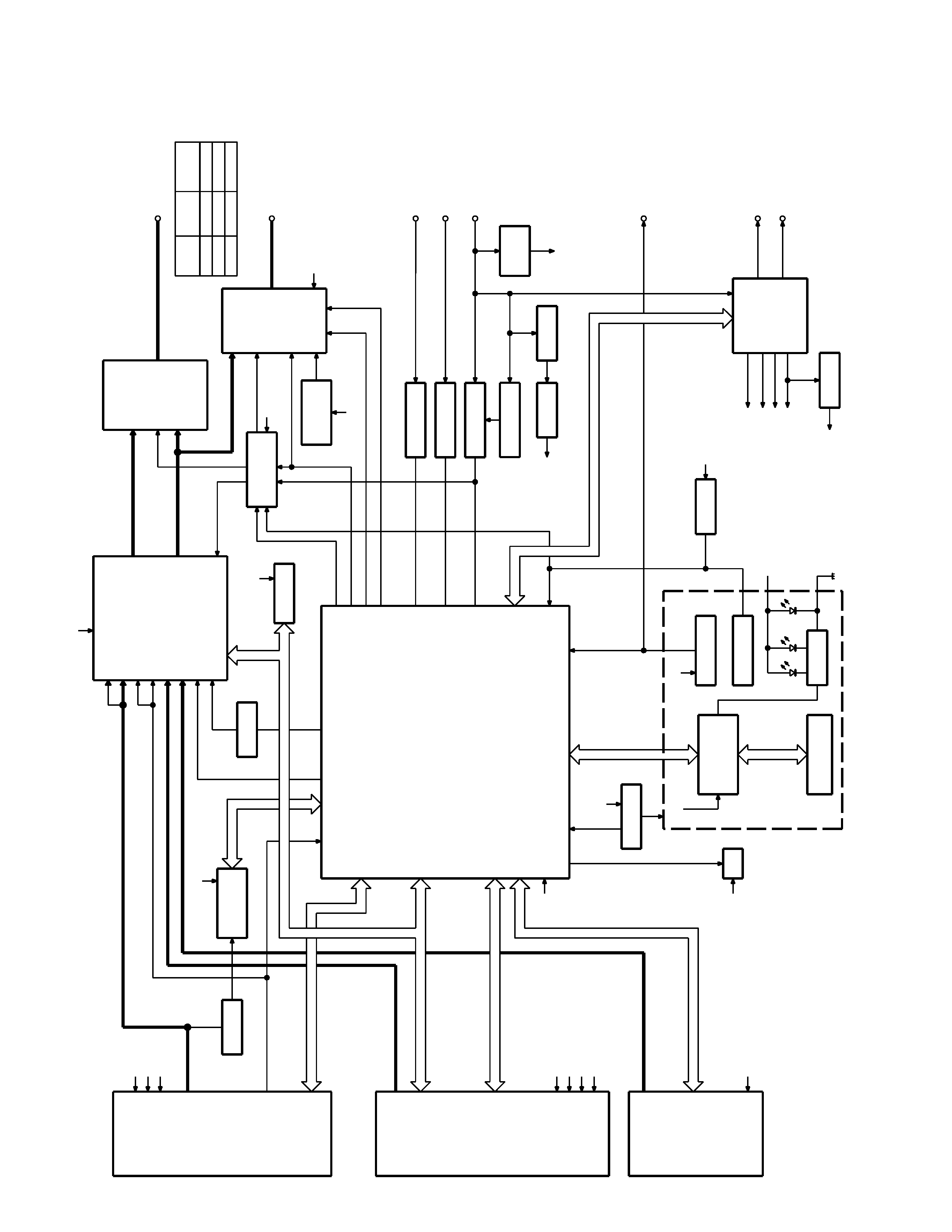
TUNER
MP3
CH
SWITCH UNIT (X16- )
BUFFER
RDS
DECODER
BUFFER
EEPROM
REMOCON
RESET SW
WITH
LCD DRIVER
KEY MATRIX
LCD
DSI
u-COM
MPX
E-VOL
&
ACC DET
TEL MUTE
B.U DET
PRE MUTE
DRIVER
MUTE
POWER
IC
THERMAL
PROTECT
ACC
TEL MUTE
BACK UP
(REAR)
PRE OUT
SP OUT
SURGE DET
SERVO
SERVO+B
SW 14V
WIRED REMO
SUPPLY
IC
POWER
ANT CON
P CON
RESET
SW 5V
PANEL 5V
SW5V
MECHA
+B
MECHA+
ILL SW
ILLUMI
IC7
IC2
IC1
IC4
IC3
IC8
IC1
IC2
S-METER
AUDIO OUT
IFC OUT
PLL-DATA
PLL-CLK
SW5V
AM+B
A8V
SW(SW3)
12EJE SW(SW2)
LO/S SW(SW1)
MS CLK
MS DATA
LO.E/LIM
M MUTE
LO/EJ
M STOP
M RST
SERVO+B
A8V
BU5V
MECHA+
DATA C
CH MUTE
CH RST
REQ H
REQ C
CH CLK
CH-CON
DATA H
BACK UP
QU
A
L
S-METER
R
D
ATA
R
CLK
FM
AM
MP
LEVEL
CD
QUAL
AFS
CH
SW5V
SW5V
BU5V
DSI
L
CLK
L
D
ATA
S
L
CE
L
D
ATA
L
REMO
MUTE
P-MUTE
PHONE
ACC DET
B.U DET
BEEP
PS1-0
PS1-1
PS1-2
PS2-0
PS2-2
RST
BU5V
BACK UP
A8V
SW5V
AM+B
ILLUMI
A8V
BU5V
BU5V
MODE
FM
AM
MP3
E-TYPE
1372mV
855mV
3600mV
K-TYPE
1800mV
600mV
3600mV
P-STBY
BU5V
TDF
DET
PANEL
BU5V
SW5V
DATA
CLK
BLOCK
DIA
GRAM
KDC-M4524/G/Y/GY
3
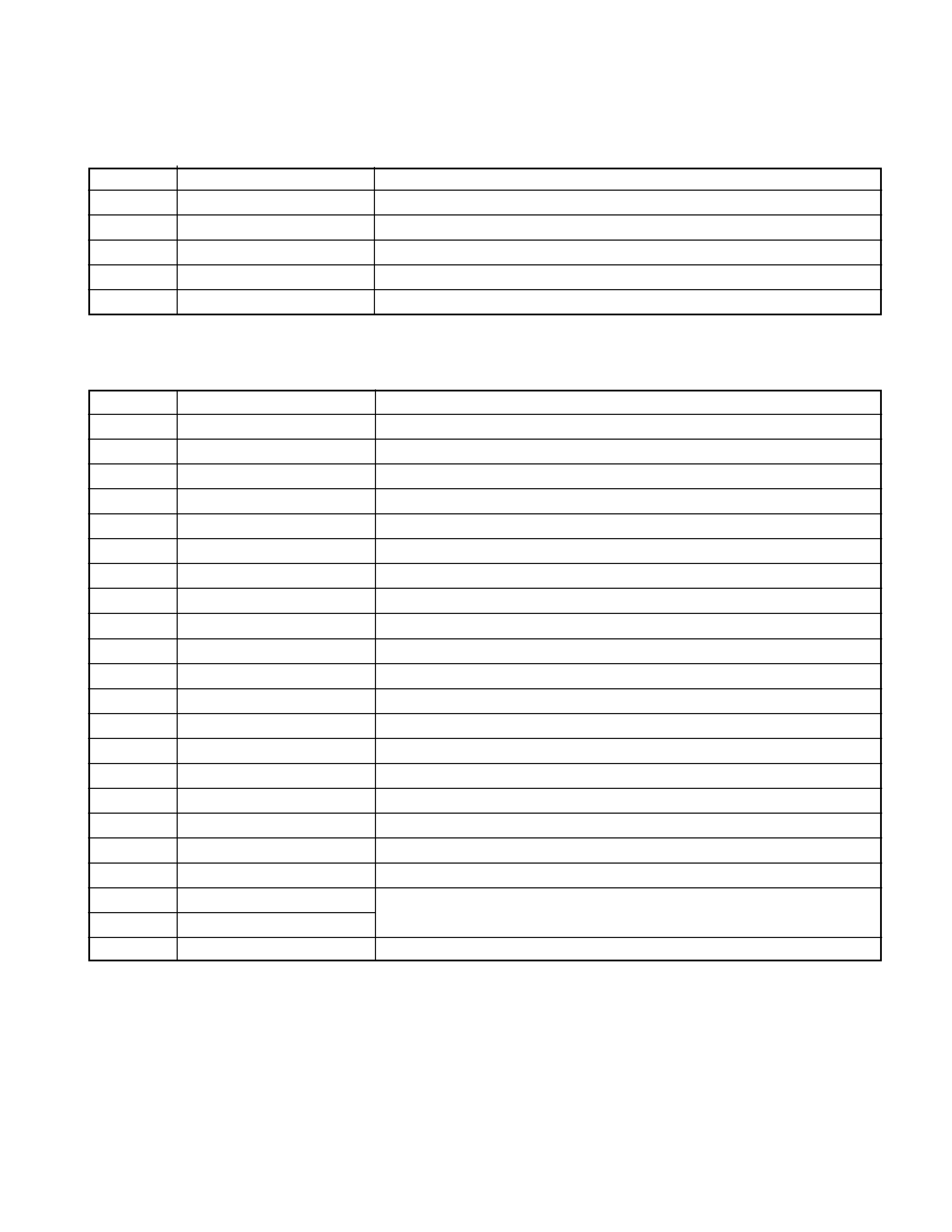
COMPONENTS DESCRIPTION
q SWITCH UNIT (X16-2052-71/2362-70)
Ref. No.
Function
Operation
IC1
LCD Driver
IC2
Remote-control IC
Q1
Key-scan Start SW
"ON" when the base goes "L".
Q2
Key-illuminations SW (GREEN)
ON (Key-illuminations Green) when the base goes "H".
Q3
Key-illuminations SW (RED)
ON (Key-illuminations RED) when the base goes "H".
q ELECTRIC UNIT (X25-9622-71/9812-70)
Ref. No.
Function
Operation
IC1
System MI-COM
IC2
E-VOL. & N.C. MPX
IC3
Power Supply IC
IC4
Power IC
IC6
Analog SW (Mute logic)
IC7
RDS Demodulator
IC8
Reset IC
"L" : detection voltage below 3.6V
IC9
CD mechanism 5V AVR
Q1
SERGE Det.
ON when the base goes "Hi".
Q2
B.U. Det.
ON when the base goes "Hi" during BU applied.
Q3
ACC Det.
ON when the base goes "Hi" during ACC applied.
Q4
SW 5V
ON when the base goes "Lo".
Q21
SERVO +B AVR
Output voltage 7.4V
Q22
SW 14V
ON when the base goes "Hi".
Q41
MECHA 5V AVR SW
ON when the base goes "Lo".
Q101
Buffer
The buffer for composite signals.
Q151
Panel 5V SW
ON when the base goes "Lo".
Q201
Noise buffer
Q350
Mute driver for Audio mute SW
ON when the base goes "Lo".
Q351
Pre mute SW
Audio Pre-output is muted when the base goes "Hi".
Q352
Pre mute SW
Q401
DSI ILLUMI SW
ON when the base goes "Lo".
KDC-M4524/G/Y/GY
4
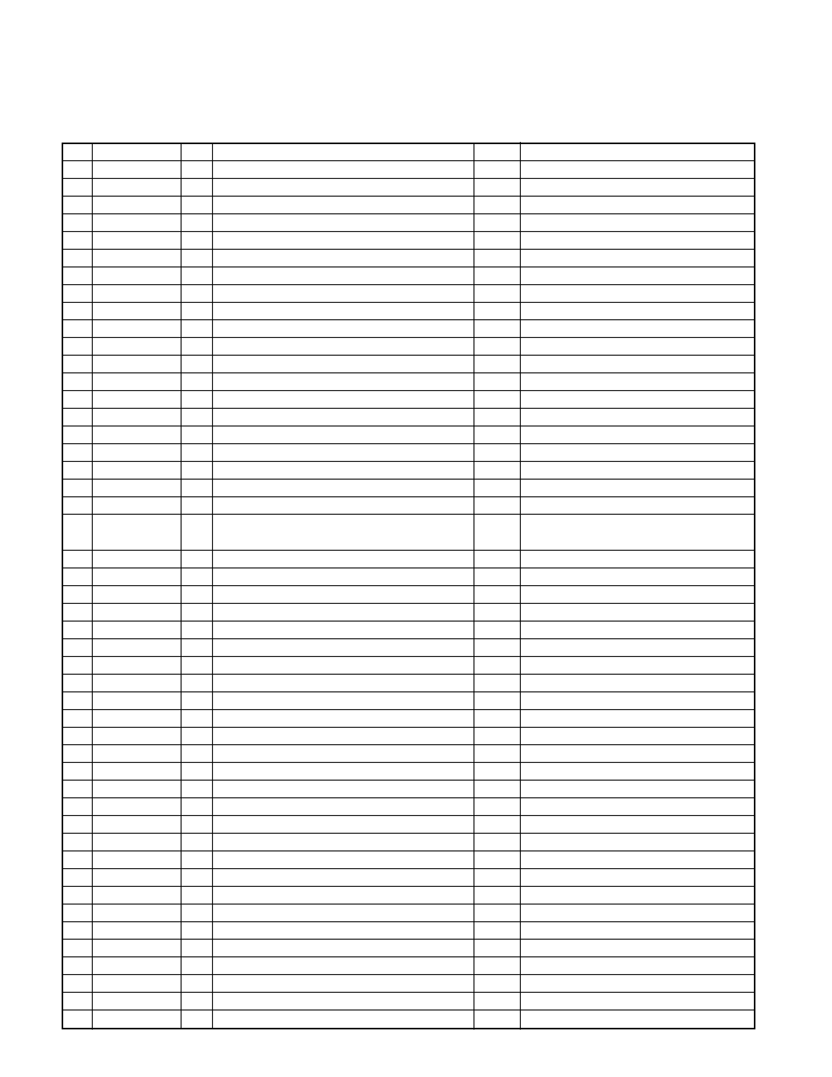
q SYSTEM MICROCOMPUTER UPD703030GC011 (IC1 : X25)
pin
pin name
I/O
Description
truth table
Processing Operation
1
PLL CLK
I/O
Clock output to F/E
2
AFS
O
Noise detection time constant switching terminal
FM seek/during/AF search : L, receiving : H
3
TDF DET
I
TDF panel detection terminal
Panel detached : H, panel attached : L
4
IC2 SDA
I/O
Data input and output terminal with E-VOL
4
IC2 SDA
I/O
Data input and output terminal with CD mechanism
4
IC2 SDA
I/O
Data input and output terminal with E2PROM
5
IC2 SCL
I/O
Clock output to E-VOL
5
IC2 SCL
I/O
Clock output to CD mechanism
5
IC2 SCL
I/O
Clock output to E2PROM
6VDD
-
7
VSS
-
8
-
O
Not used
9
BEEP
O
Beep output terminal
10
REMO
I
Remote control input
11
R QUAL
I
RDS decoder quality input terminal
11
-
O
Not used
With no RDS and destination is output L
12
R DATA
I
RDS decoder data input terminal
12
-
O
Not used
With no RDS and destination is output L
13
L CE
O
CE output to LCD driver
14
-
O
Not used
15
L INH
O
Reset output to LCD driver
Display light off, KEY reset : L Display light on,
KEY scan : H
16
DSI
O
DSI control terminal
DSI light on : H, Light off : L
17
-
O
Not used
18
TEST
-
19~21 -
O
Not used
22
MOSW
O
CD mechanism motor IC switch
e
Loading/Eject/Break : H
23
LO/EJ
I/O
CD mechanism Loading/Eject switch
e
Stop/Break : Hi-Z Loading : L Eject : H
24
M STOP
O
Stop request to CD mechanism
25
M RST
O
Reset output to CD mechanism
Usually : H, Reset : L
26
MUTE
I/O
Mute terminal
L : MUTE OFF, H : MUTE ON
27
LO.E/LIM SW (SW3)
I
CD Down Switch detection terminal
H : chucking
28
M MUTE L
I
MUTE request from CD mechanism
L : MUTE request
29
M MUTE R
I
MUTE request from CD mechanism
L : MUTE request
30
-
O
Not used
31
RESET
I
Usually : H, Reset : L
32
XT1
I
Sub clock 32.765kHz
33
XT2
I
Sub clock 32.765kHz
34
REGC
-
Ceramic capacitor connected to the pair grounds
35
X2
I
Main clock 20MHz
36
X1
I
Main clock 20MHz
37
VSS
-
38
VDD
-
39
CLKOUT
-
40
IC2 TYPE1
I
E-VOL setting switching terminal
41
IC2 TYPE0
I
E-VOL setting switching terminal
42
-
O
Not used
43
TYPE1
I
Destination switching terminal
r
44
TYPE0
I
Destination switching terminal
r
MICROCOMPUTER'S TERMINAL DESCRIPTION
KDC-M4524/G/Y/GY
5
pin
pin name
I/O
Description
truth table
Processing Operation
45
CD MECHA+B
I/O
Power supply control terminal for MP3
ON : L, OFF : Hi-Z
46
SW5V
I/O
Control terminal for switch5V
ON : L, OFF : Hi-Z
47
PS2-0
O
Control terminal for power supply IC
w
48
PS2-1
O
Control terminal for power supply IC
w
49
PS1-0
O
Control terminal for power supply IC
q
50
PS1-1
O
Control terminal for power supply IC
q
51
PS1-2
O
Control terminal for power supply IC
q
52
BU DET
I
BU detection terminal
BU detection : L, with no BU : H
53
ACC DET
I
ACC detection terminal
ACC detection : L, with no ACC : H
54
-
O
Not used
55
BVDD
-
56
BVSS
-
57,58 -
O
Not used
59
P-MUTE
O
POWER IC MUTE output terminal
POWER OFF : L, ALLOFF : L, TEL MUTE : L
60
P-STBY
O
POWER IC STBY output terminal
POWER IC ON : H, OFF : L
61,62 -
O
Not used
63
PRE MUTE
O
PREOUT MUTE output
during momentary power down L,
When M-MUTEL : L
64~67 -
O
Not used
68
LX-RST
O
Reset output to external unit
Usually, L after system RST returned,after
more than 400m sec H,and L
69
LX-CON
O
Control output to external unit
ON : H, OFF : L
70
AVCONT
O
AD reference voltage control output
during motion : H
71
AVDD
-
72
AVSS
-
73
AVREF
-
Connection with 70pin
74
PHONE
I
PHONE detection terminal
TEL MUTE : 1V orless, NAVI MUTE : more
than 2.5V
74
-
I
Not used (with no PHONE destination)
75~81 -
I
Not used
82
S-METER
I
S-meter detection terminal
Dependant for control use of tuner
83
NOISE
I
FM noise detection terminal
Dependant for control use of tuner
84
IFC-OUT
I
F/E IFC OUT input terminal
Dependant for control use of tuner
85
LX-MUTE
I
MUTE request to external unit
H : MUTE ON, L : MUTE OFF
86
LX-REQM
O
Request output to external unit
Request detection : L
87
R CLK
I
RDS decoder Clock input terminal
87
-
O
Not used
Destination with no RDS : output L fixed
88
LX-REQS
I
Request intput to external unit
Request detection : L
89
KEY-REQ
I
Request of communication from LCD driver
L : KEY input
90
LO.S SW (SW1)
I
Loading start switch detection terminal
Loading start : L
91
12EJE SW (SW2)
I
12cmDISK EJECT position detection switch terminal
12cmDISC : L
92
-
O
Not used
93
-
O
Not used
94
LX-DATAS
I
Data input from external unit
95
LX-DATAM
O
Data output to external unit
Holding the last
96
LX-CLK
I/O
Clock output and input terminal with external unit
97
L DATAL
I
Data input from LCD driver
98
L DATAS
O
Data output to LCD driver
99
L-CLK
I/O
Clock output to LCD driver
100 PLL DATA
I/O
Data output and input terminal with F/E
MICROCOMPUTER'S TERMINAL DESCRIPTION
KDC-M4524/G/Y/GY