© 2004-3 PRINTED IN JAPAN
B53-0152-00 (N) 2703
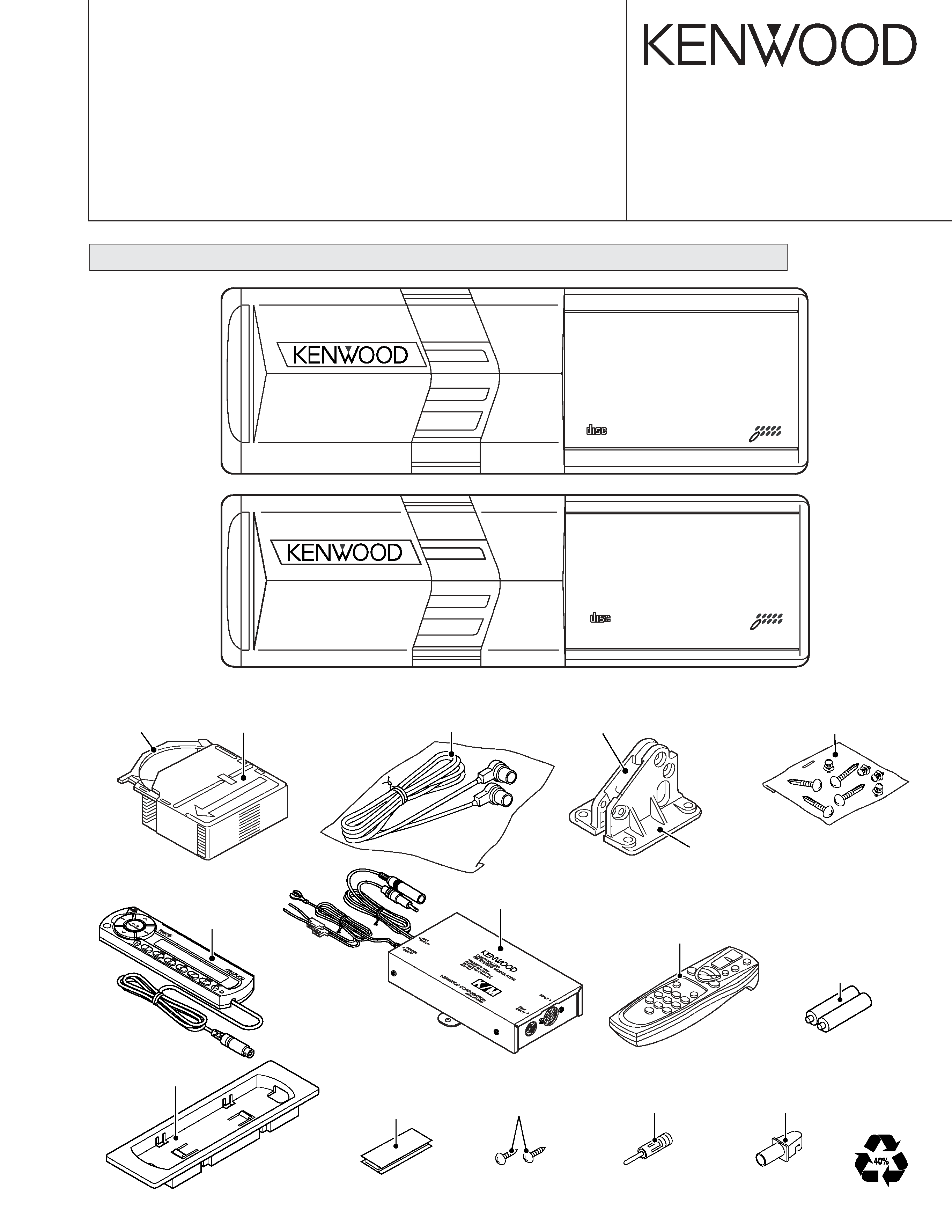
CD AUTO CHANGER
KDC-C471FM
KDC-C521FM
SERVICE MANUAL
Size AAA battery
(Not supplied)
(E type only)
(E type only)
Remote controller assy
(A70-2051-05) (RC-535) : KDC-C521FM
(A70-2052-05) (RC-525) : KDC-C471FM
Velcro
(W01-1633-08)
Unit holder
(J19-7009-08)
Screw
(N99-1755-08) x2
Antenna adaptor
(T90-0512-05)
Antenna adaptor
(T90-0521-05)
COMPACT DISC AUTO CHANGER
KDC-C521FM
NEW ANTI VIBRATION MECHANISM
10DISC
COMPACT
DIGITAL AUDIO
CD-R/RW
1BIT
4D/A CONVER
COMPACT DISC AUTO CHANGER
KDC-C471FM
NEW ANTI VIBRATION MECHANISM
6 DISC
COMPACT
DIGITAL AUDIO
CD-R/RW
1BIT 4D/A CONVERTER
Holder assy
(J19-5146-02) : KDC-C521FM
(J19-5149-02) : KDC-C471FM
Tray
(J99-0614-01)
Cord with plug (5m)
(E30-4711-05)
Bracket
(J19-5018-03) : KDC-C521FM
(J19-5020-03) : KDC-C471FM
Screw set
(N99-1645-15)
Control unit
(Display unit)
RF Modulator
Except KDC-C471FM (K type)
KDC-C521FM
KDC-C471FM
Bracket
(J19-5019-03) : KDC-C521FM
(J19-5021-03) : KDC-C471FM
When transporting these models, always attach CAUTION CARD and STEPPED SCREW (for transportation).
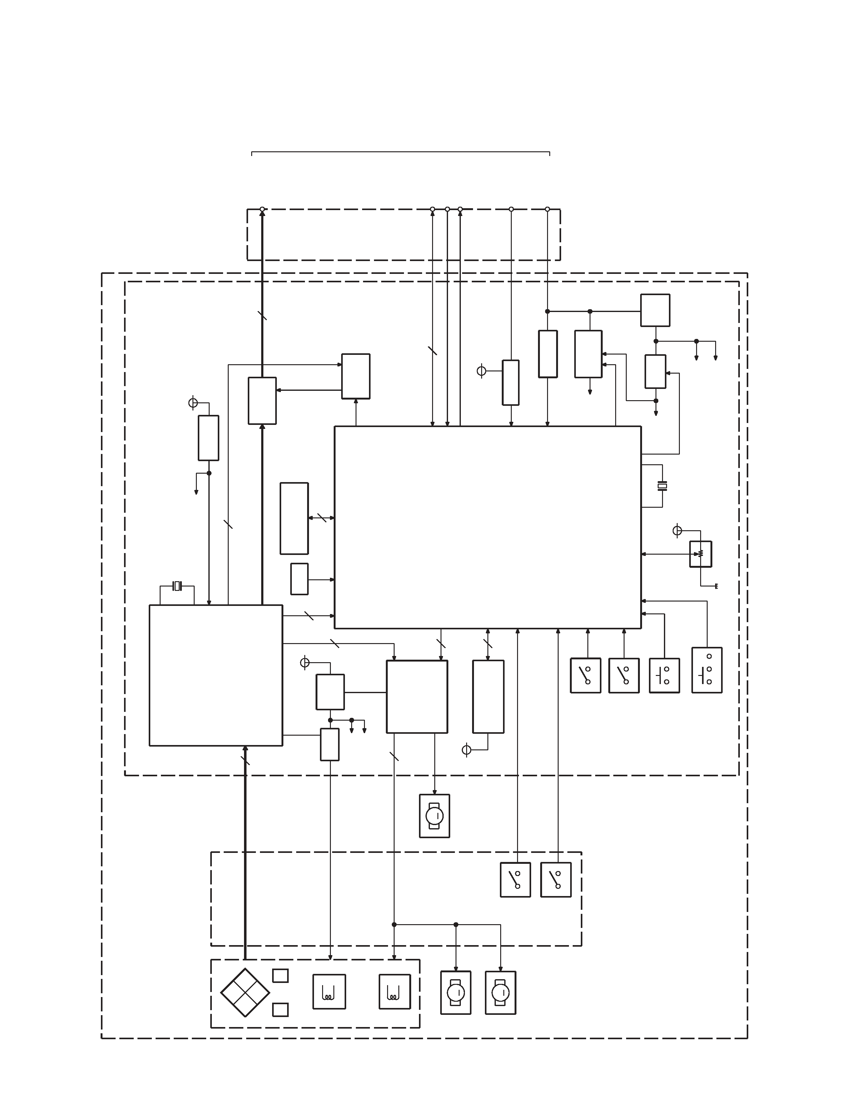
KDC-C47
1FM/C52
1FM
2
BLOCK
DIA
GRAM
SW5V
LIM SW
L.P.S.
EJ SW
ARM SW
12.5MHz
X2
SPINDLE/LO-EJ
SLED
LOE SW
TR COIL
FO COIL
BTL
EEPROM
&TEXT DECODER
APC
SA5V
Q1
S8V
SYSTEM u-COM
IC7
IC1
RF AMP&SARVO DSP
16.93MHz
X1
P-ON
Q10
Q15,16
Q20
BU. DET
IC8
7
13
4
5
8
2
IC5
MG SW
8V AVR
S8V
S-RAM
24
C
2
BU14V
CH RST
AUDIO
OUT
5
5VREG
IC4
DA5V
S8V
3
HOT
IC9
RESET
7V/9V
5V
Q21,22
M5V1
M5V2
SW5V
S3
S2
S1
SW5V
M
M
&DC MOTOR
DRIVER
ELEVATOR
M
AVR
SA5V
Q9
&D/A CONVERTER
&SCF
MUTE
0bit
Q6,7
MUTE
Q4,5,8
SD5V
F
E
A
D
B
PD
M5V2
AVR
CH-MUTE
CH-CON
5L I/F
IC11
COMM SW
S4
to
HEAD
UNIT
ASSY
(X13)
(X32)
(X13)
(X92)
PICKUP
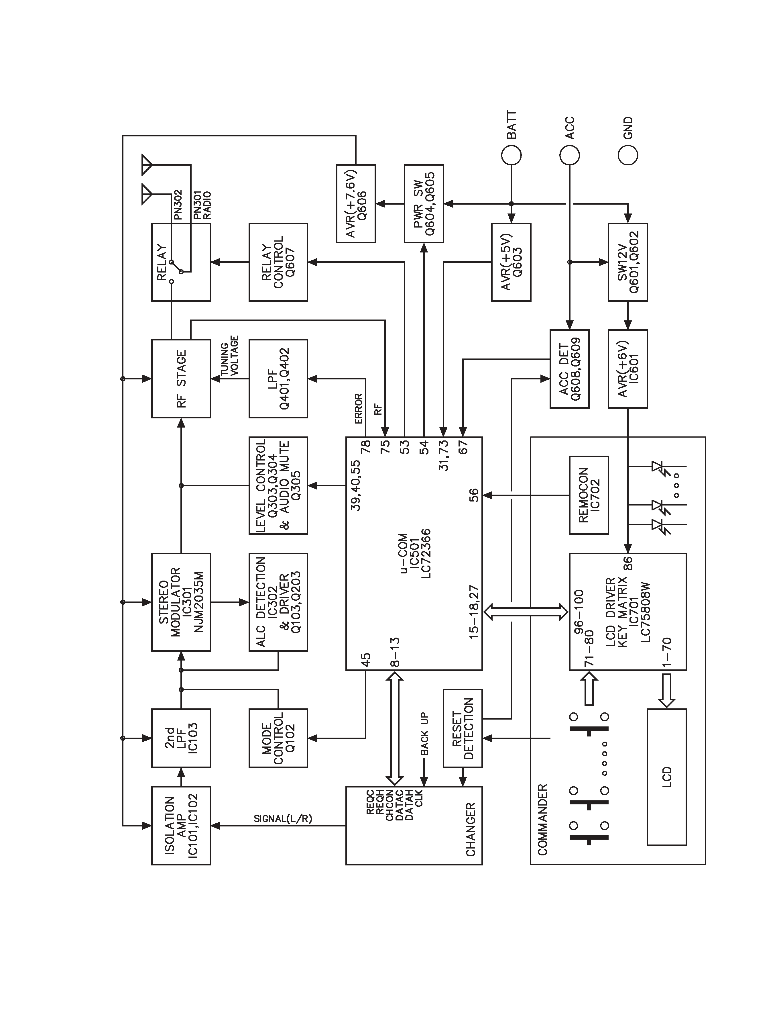
KDC-C4
71FM/C52
1FM
3
BLOCK
DIA
GRAM
(FM MODULATOR)
KDC-C471FM/C521FM
4
CD PLAYER UNIT (X32-5470-01)
Ref. No.
Application / Function
Operation / Condition / Compatibility
RF amplifier built in digital servo and data processor IC. Focusing, tracking, sled and
spindle servo processing. Detection of dropout, anti-shock, track crossing and off-track
IC1
Servo IC
conditions.
Automatic adjustment (focusing, tracking, gain, offset and balance) operations.
Digital signal processing (DSP, PLL, sub-codes, CD-TEXT decode, CIRC error
correction, audio data interpolaration) operations.
IC4
+5V AVR
Analogue output circuit power supply for D/A converter.
Focusing coil, tracking coil, spindle motor and sled motor driver.
VO1~VO4 and VOL outputs ON/OFF function.
While MUTE1 goes "Hi", VO1 outputs are turned on.
While MUTE2 goes "Hi", VO2~VO4 and VOL outputs are turned on.
VIN1 amplifier function (input selection and VREF selection)
IC5
Motor driver
1. Input selection.
While VIN SW terminal goes "Lo", IC pin 15, 16 and 17 inputs are selected.
While VIN SW terminal goes "Hi", IC pin 15, 18 and 19 inputs are selected.
2. VREF selection.
While VIN SW terminal goes "Lo", internal VREF (2.5V typical) is selected.
While VIN SW terminal goes "Hi", external VREF (IC pin 30 input) is selected.
IC7
Mechanism
µ-COM
Mechanism and servo control.
IC8
EEPROM
LPS data back-up memory.
IC9
Reset IC
When BU 5V voltage is less than 3.0V, IC outputs "Lo".
Q1
APC
Laser diode auto power control.
Q4
0 bit mute (L CH.)
When 0 bit mute is activated, an emitter goes "Hi", and Q4 outputs "Hi".
Q5
0 bit mute (R CH.)
When 0 bit mute is activated, an emitter goes "Hi", and Q5 outputs "Hi".
Q6
Mute SW (L CH.)
When 0 bit mute or A mute drive is activated, a base goes "Hi", and L channel audio
signal is muted.
Q7
Mute SW (R CH.)
When 0 bit mute or A mute drive is activated, a base goes "Hi", and R channel audio
signal is muted.
Q8
A mute drive
When audio mute of IC7 is activated, a base goes "Lo", and audio mute drive signal is
outputted.
Q9
Servo 5V AVR
Q9 is combined with IC5's pin 26 and 27, and works as a driver of AVR.
Q10
P-ON 5V SW
While base goes "Lo", P-ON 5V is supplied to the microprocessor peripheral circuits.
Q11
Reset SW
When System Reset has activated, a base goes "Hi", and Q11 is turned on.
Q13
CH CON SW
While CH CON or CH-CON2 mode is selected, a base goes "Hi", and Q13 is turned on.
Q14
CH MUTE SW
When MUTE REQUEST to H/U is outputted, a base goes "Lo", and Q14 is turned on.
Q16
SRV 8V AVR
Q16 is combined with Q15 (X92-), and works as a pre-driver of AVR.
Q17,18
SRV 8V AVR SW
When Q18's base goes "Hi", Q17 is turned on, and SVR 8V AVR is working.
Q19
7/9V SW
When a base goes "Hi", Q19 is turned on, and SVR 8V AVR is outputting +7V.
When a base goes "Lo", Q19 is turned off, and SVR 8V AVR is outputting +8.5V.
Q20
BU DETECTION SW
While BACKUP is applied, a base goes "Hi", and Q20 is turned on.
When momentary power down has detected, a base goes "Lo", and Q20 is turned off.
COMPONENTS DESCRIPTION
KDC-C471FM/C521FM
5
Ref. No.
Application / Function
Operation / Condition / Compatibility
Q21,22
BU 5V AVR
While BACKUP is applied, AVR outputs +5V.
Q21 and Q22 are inverted Darlington connection.
Q30
Eccentric disc SW
When an eccentric disc is detected, Q30 is turned on, and a preceding beam is made to
be delayed.
Q31
VIN SW
While spindle servo or disc loading/eject mode is selected, a base goes "Hi", and Q31 is
turned on.
CONTROL UNIT
Ref. No.
Application / Function
Operation / Condition / Compatibility
IC701
LCD Driver with Key-matrix
IC702
Remote Control Light Sensor
Q701
LED ON/OFF SW
Q702
Key-matrix Permission SW
Q703
Remote Control ON/OFF SW
FM MODULATOR UNIT
Ref. No.
Application / Function
Operation / Condition / Compatibility
IC101,102
GND Isolation AMP
IC103
Low Pass Filter
IC301
FM Stereo Modulator
IC302
1/2 Vcc Driver, ALC Detection Amp
IC501
System
µcom
IC601
6V AVR
Q102
L/R Mixer SW
D.cont off : L, D.cont on : H
Q103,203
ALC Control SW
Q301
Composite Buffer
Q303,304
Level Control SW
LEVEL 1/2 : L, LEVEL 3/4 : H, LEVEL 2/4 : L, LEVEL 1/3 : H
Q305
Audio Mute
Power on : L, Power off : H
Q351
Temperature compensation
Q401,402
PLL Low Pass Filter
Q411
RF Amp
Q501
Changer Reset SW
Q502
Reset SW
Q601,602
Display Unit Power SW
Q603
Backup 5V AVR
Q604,605
Power SW
Q606
8V AVR
Q607
Relay Driver
Q608
ACC Detection
Q609
Hold Detection
COMPONENTS DESCRIPTION