Extension cord
Parts No.
CD mechanism(22P)
W05-0618-00
The MECHANISM OPERATION DESCRIPTION is the same as model KDC-S3007 and KDC-5050RG.
Please refer to the service manual for model KDC-S3007(B51-7029-00) or KDC-5050RG(B51-7099-00).
F1
F1
EJECT
KDC-6016R
45W 4
X
PWR
OFF
TI
LOUD
VOL ADJ
MENU
DISP
NAME.S
SCAN
RDM
REP
D.SCN
M.RDM
DISC
DISC
PTY
DAB
AUD
EJECT
KDC-5080R
PWR
OFF
TI
LOUD
VOL ADJ
MENU
DISP
NAME.S
SCAN
RDM
REP
D.SCN
M.RDM
DISC
DISC
PTY
DAB
AUD
45W 4
X
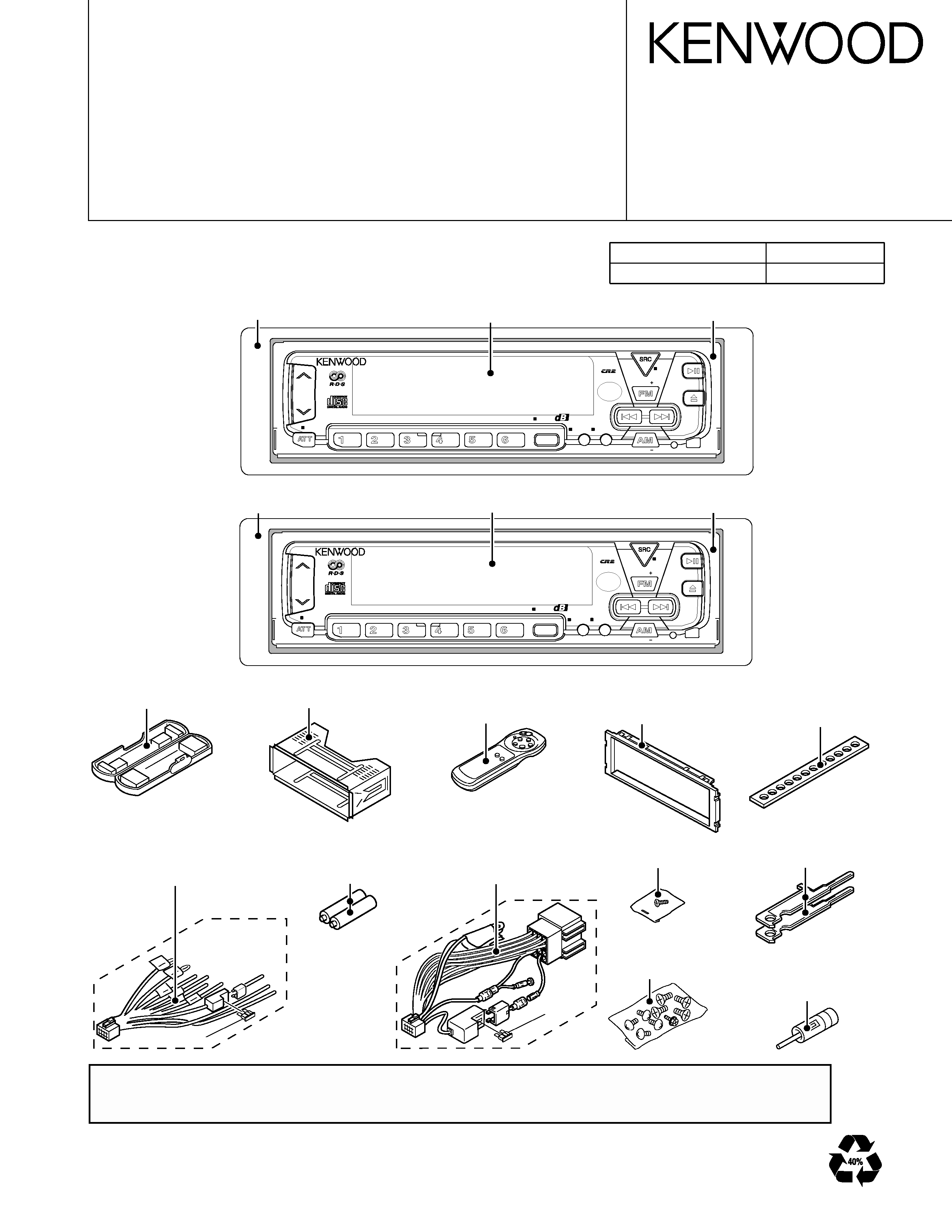
KDC-5080R/RY
KDC-6016R
Escutcheon assy
(B07-2195-08)
Front glass assy
(B10-3215-08)
Panel assy
(A64-2092-08)
Escutcheon assy
(B07-2195-08)
Front glass assy
(B10-3214-08)
Panel assy
(A64-2092-08)
Plastic cabinet assy
(A02-1494-08)
Mounting hardware assy
(J21-9585-08)
Remote controller assy
(A70-0883-05)
:KDC-6016R
Battery(size:AAA)
Not supplied as
service parts
DC cord
(E30-4868-08)
:KDC-6016R
DC cord
(E30-4869-08)
:KDC-5080R/RY
Screw set
(N99-1688-08)
Screw set
(N99-1689-08)
:KDC-6016R
:KDC-6016R
(J54-0611-08)
Stay
Escutcheon(J CAR)
(B07-2186-08)
:KDC-6016R
:KDC-5080R/RY
Ant adapter
(T90-0523-05)
Lever
(D10-4514-08)x2
© 2000-2 PRINTED IN JAPAN
B51-7593-00 (N) 2209
CD RECEIVER
SERVICE MANUAL
KDC-5080R/RY,
KDC-6016R

KDC-5080R/RY,6016R
2
CONTENTS
BLOCK DIAGRAM ......................................................................................... 3
COMPONENTS DESCRIPTION .................................................................... 4
MICROCOMPUTER'S TERMINAL DESCRIPTION ....................................... 6
TEST MODE .................................................................................................. 8
ATTENTION ................................................................................................... 9
PC BORD .....................................................................................................10
SCHEMATIC DIAGRAM ..............................................................................17
EXPLODED VIEW ........................................................................................25
PARTS LIST .................................................................................................27
SPECIFICATIONS ........................................................................................34
KDC-5080R/RY,6016R
3
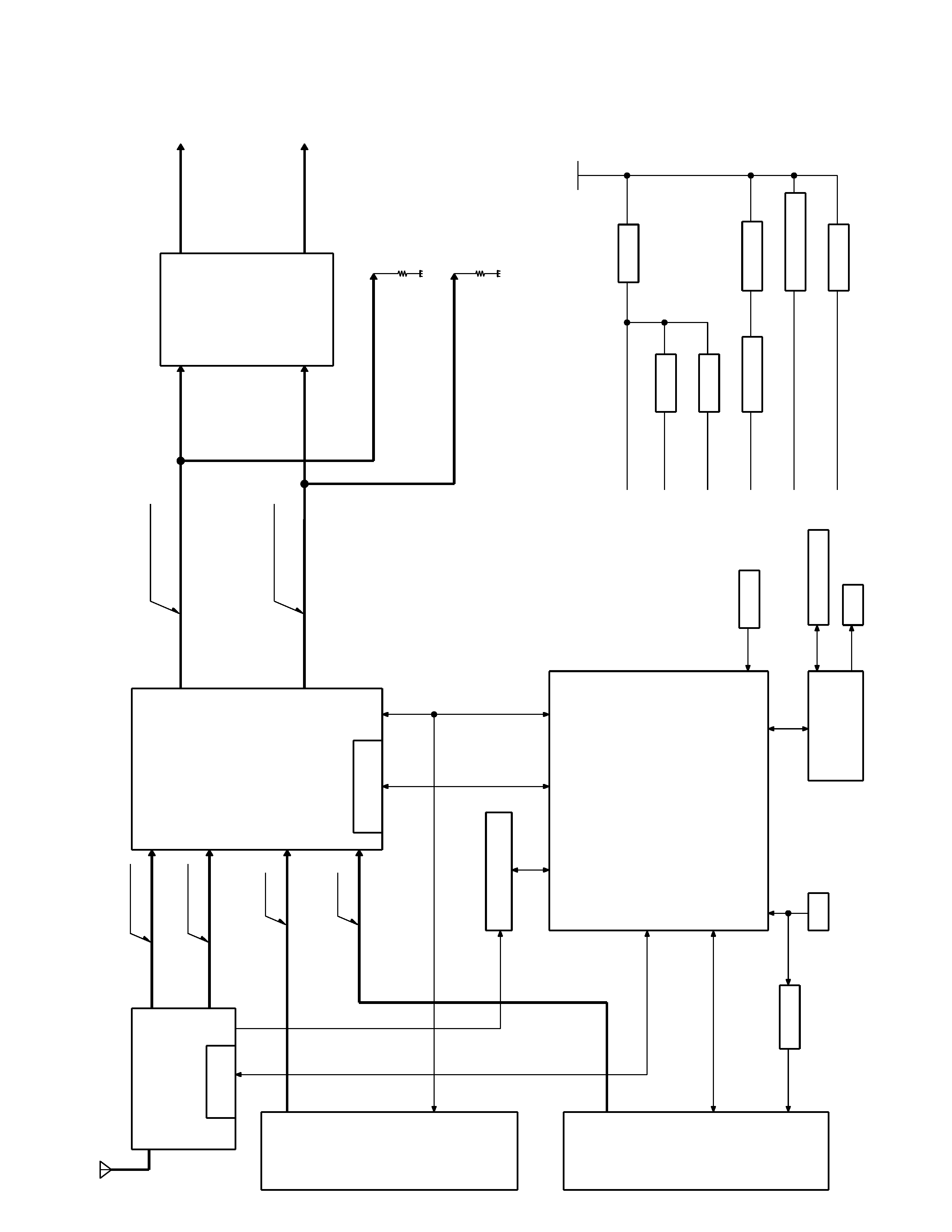
BLOCK DIAGRAM
REAR
FR
ONT
REAR
FR
ONT
B
U5V
SW5V
PNL5V
AIDIO
8V
SER
V
O
7.5V
ILL
11V
FR
ONT
10K
10K
REAR
FR
ONT
REAR
FM
AM
CD
CD-CH
2
PO
WER
IC
B
U
5V
SW
5V
PNL
5V
A
UDIO
8V
SW
14V
SER
V
O
7.5V
ILL
11V
B
U
14V
RDS
DETECT
OR
TUNER
ANT
E
PR
OM
E-V
OL
NOISE
AMP
CD
u-COM
CD-CH
RST
LCD-Dr
REMO
KEY
MA
TRIX
LCD
TU100,
Q100-104
IC1
RST
SW
Q3
IC2
IC900
IC901
IC300
IC150
IC500
Q1
Q5
Q622,
625
Q621,
624
Q618,
620
Q612,
614,
615
Q610,
611
Q300-302
CD
AM(E)
AM(M)
FM(E)
FM(M)
CD-CH
1250mV
(E)
(M)
(E)
(M)
1200mV
FM(M)
CD
AM
FM(E)
CD-CH
FM(M)
CD
FM(E)
AM(M)
AM(E)
CD-CH
FR
ONT
REAR
CD-CH
CD
AM(E)
AM(M)
FM(E)
FM(M)
:730mV
:560mV
:1280mV
:1660mV
:2900mV
:2930mV
:400Hz
40KHz
De
v
:400Hz
75KHz
De
v
:1KHz
0dB
:400Hz
30%
Mod
:1KHz
0dB
:2690mV
:670mV
:1180mV
:2650mV
:2650mV
:510mV
:1530mV
:2690mV
:1180mV
:670mV
:1530mV
:510mV
:170mV
:350mV
:150mV
:140mV
AM+B
FM+B
SMETER
SD
SCL
SD
A
IF
COUNT
REQ
C
REQ
H
D
ATA
C
D
ATA
H
CLK
CH-CON
MUTE
RST
DATA
S
DATA
L
CE
INH
CLK
SRQ
MUTE
CLK
SW3
SW2
SW1
D
ATA
S
D
ATA
H
MO
SW
ST
OP
RST
LO/EJ
CS
SDA
SCL
:2930mV
CD
:2900mV
CD-CH
:560mV
:730mV
:1660mV
:1280mV
FM(E)
AM(M)
AM(E)
FM(M)
RDDA
QUA
L
RDCL
AFC
NOISE
KDC-5080R/RY,6016R
4
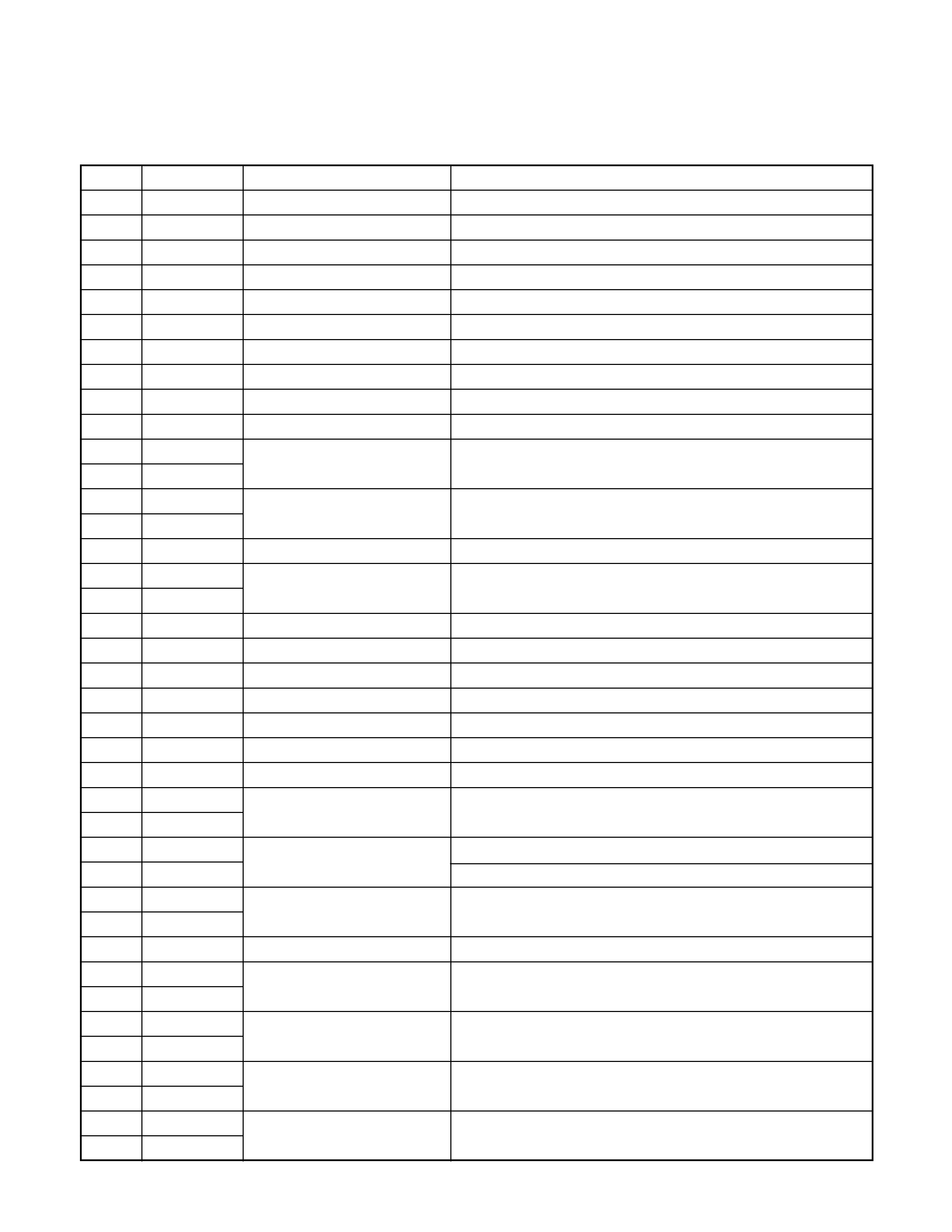
COMPONENTS DESCRIPTION
MAIN UNIT
Ref.No.
Component Name
Application/Function
Operation/Condition/Compatibility
IC1
784217AGF505 System MI-COM.
IC2
S-80830ANNP Reset IC
"Lo": Detection voltage below 3.0V
IC3
HD74HC27FP
Mute logic
3 input NOR gate x3
IC150
TDA7479D
RDS decoder
IC300
TDA7400D
E-VOL. & N.C. MPX
IC500
TDA7386
Power IC
Q1
2SA1576A
SW 5V
ON when the base goes "Lo".
Q2
DTA124EUA
Mute driver for Audio mute SW
ON when the base goes "Lo".
Q3
DTA144EUA
Changer reset SW
ON when the base goes "Lo".
Q5
2SA1576A
Panel 5V SW
ON when the base goes "Lo" during the panel not detached.
Q100
2SA1703-AN
FM+B SW
Q100 is turned ON when Q101's base goes "Hi".
Q101
DTC144EUA
ON during FM reception.
Q102
2SA1703-AN
AM+B SW
Q102 is turned ON when Q103's base goes "Hi".
Q103
DTC144EUA
ON during AM reception.
Q104
2SC4081
Composite out buffer
Q300
DTA124EUA
Noise detection time constant SW
OFF during FM seek, ON during FM reception.
Q301
DTC114TUA
Q301 is turned On when Q300's emitter goes "Hi".
Q302
2SC4081
Noise buffer
Q303
DTC144EUA
E-VOL. mute SW
E-VOL. is muted when the base goes "Hi".
Q350A,B DTC343TK
Audio mute SW
Audio pre-outs are muted when the base goes "Hi".
Q351A,B DTC343TK
Audio mute SW
Audio pre-outs are muted when the base goes "Hi".
Q500
DTC114YUA
SVR SW
POWER IC RESET is activated when the base goes "Hi".
Q600
2SC4081
BU detection(Momentary power down detection) ON when the base goes "Hi" during BU applied.
Q601
2SC4081
ACC detection
ON when the base goes "Hi" during ACC applied.
Q604
2SA1703-AN
P CON SW
Q604 is turned ON when Q607's base goes "Hi".
Q607
DTC114EUA
ON during POWER ON mode except ALL OFF mode.
Q605
2SA1576A
P CON protection
Protect Q604 by turning ON when P-CON output is grounded.
Q606
DTA124EUA
Prevents Q605 tuning ON during start-up after power ON.
Q610
2SB1565(E,F)
BU 5V AVR
Inverted darlington connection.
Q611
2SC4081
ON during BU applied.
Q612
2SD1760
Illumination AVR
ON when the base goes "Hi".
Q614
DTA124EUA
Illumination AVR SW
Q614 is turned ON when Q615's base goes "Hi".
Q615
DTC124EUA
Q618
2SB1565(E,F)
Servo AVR
Inverted darlington connection.
Q620
2SC4081
Q618 is turned ON when Q620's base goes "Hi".
Q621
DTA124EUA
SW 14V
Audio 8V AVR and Servo AVR ON/OFF control.
Q624
DTC144EUA
Q621 is turned ON when Q624's base goes "Hi".
Q622
2SB1565(E,F)
Audio 8V AVR
Inverted darlington connection.
Q625
2SC4081
Q622 is turned ON when Q625's base goes "Hi".
KDC-5080R/RY,6016R
5
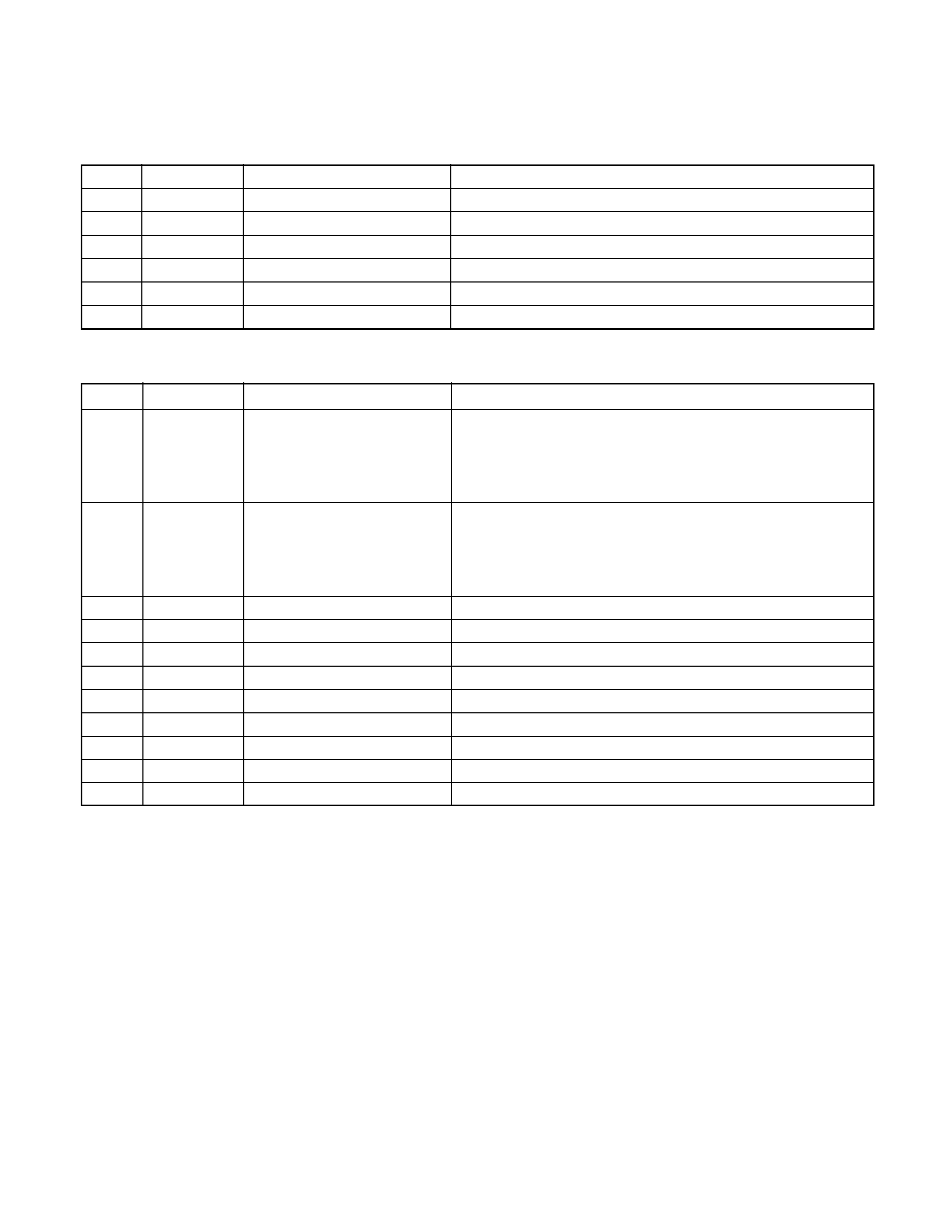
COMPONENTS DESCRIPTION
CONTROL UNIT
Ref.No.
Component Name
Application/Function
Operation/Condition/Compatibility
IC900
LC75883E
LCD driver with key-matrix
IC901
RS-171
Remote control IC
Q900
DTA124EUA
Remote SW
ON when the base goes "Lo".
Q901
2SD2114K
Key illumination green SW
ON when the base goes "Hi".
Q902
2SD2114K
Key illumination red SW
ON when the base goes "Hi".
Q903
DTA124EUA
Key-matrix permission SW
ON when the base goes "Lo".
CD PLAYER UNIT(X32-4700-00)
Ref.No.
Component Name
Application/Function
Operation/Condition/Compatibility
IC1
AN8806SB
RF amplifier
Generation of RF signal based on the signals from the APC
circuit and pickup, and generation of servo error(focusing
error and tracking error)signals. Detection of dropout, anti-
shock, track crossing and off-track conditions.
IC2
MN662774KC3
CD signal processor bult-in MI-COM.
Focusing, tracking, sled and spindle servo processing. Auto-
matic adjustment(focusing, tracking, gain, offset and
balance)operations. Digital signal processing(DSP, PLL, sub-
codes, CIRC error correction, audio data interpolaration)operations.
IC4
BA5917AFP
BTL driver
Focusing coil, tracking coil, spindle motor and sled motor driver.
IC5
TA78L05F
5V AVR
IC6
NJM4565MD
Low pass filter
Q1
2SB1188
APC
LD power control.
Q2
DTC124EUA
P ON SW
ON during the CD source selected.
Q3
2SA1362(Y)
A.8V SW
A8V line ON/OFF control.
Q4
2SA1362(Y)
D.5V SW
D5V line ON/OFF control.
Q5
DTC124EUA
MOTOR ON SW
ON during CD loading or eject action .
Q8
DTC124EUA
GAIN CONTROL SW