© 2003-11 PRINTED IN JAPAN
B53-0105-00 (N) 1839
CD RECEIVER
KDC-5027/5027Y/508
SERVICE MANUAL
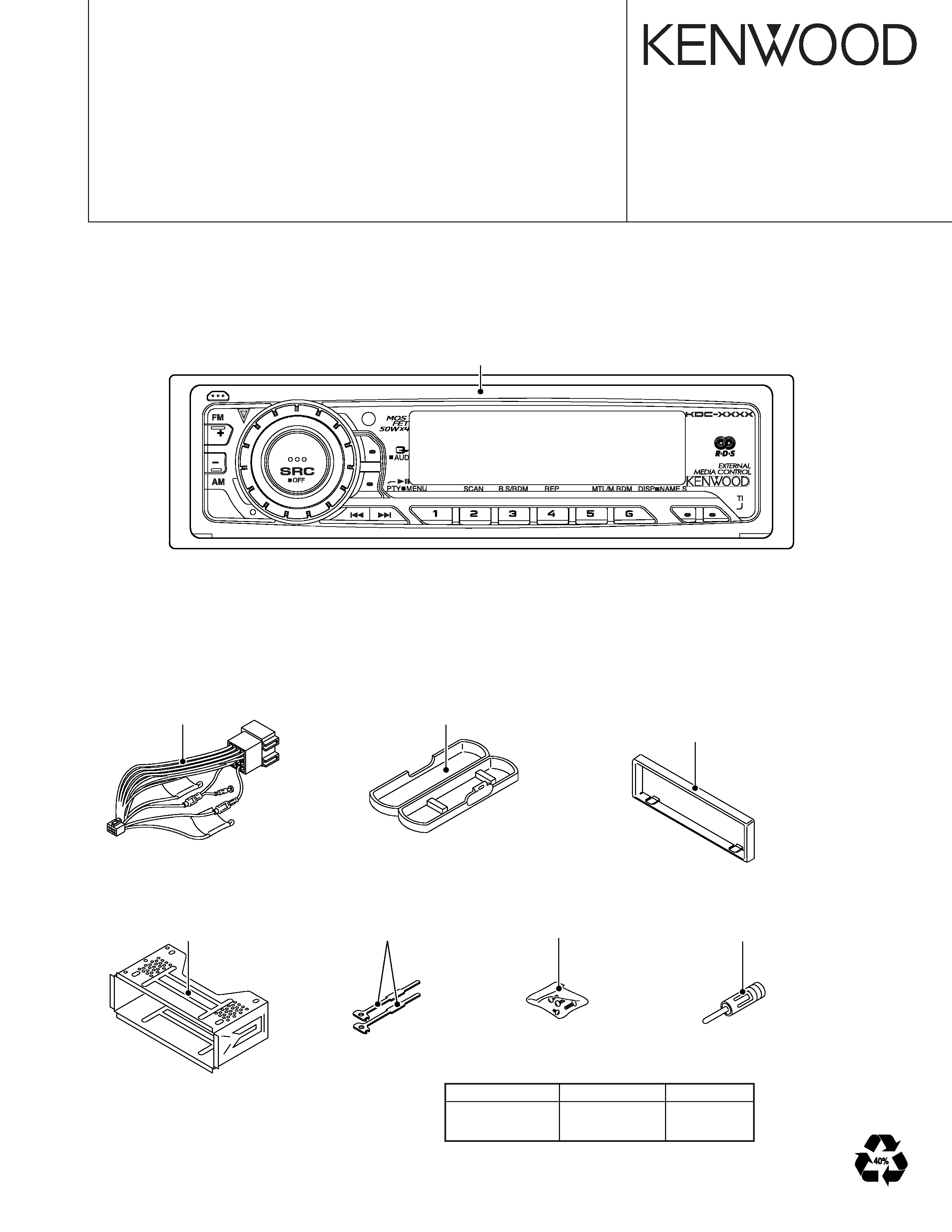
Panel assy
(A64-3195-02):KDC-5027/5027Y
(A64-3196-02):KDC-508
Plastic cabinet assy
(A02-1486-13)
Lever
(D10-4589-04) x2
Screw set
(N99-1730-15)
DC cord
(E30-6132-15)
Escutcheon
(B07-3001-02):KDC-508
(B07-3083-02):KDC-5027/5027Y
Mounting hardware assy
(J22-0011-03)
Antenna adaptor
(T90-0523-05)
CD MECHANISM EXTENSION CORD : W05-0618-00
TDF PANEL INFORMATION
MODEL
TDF PANEL No.
TDF NAME
KDC-5027/5027Y
Y33-1930-64
TDF-5027
KDC-508
Y33-1930-65
TDF-508
KDC-5027/5027Y/508
2
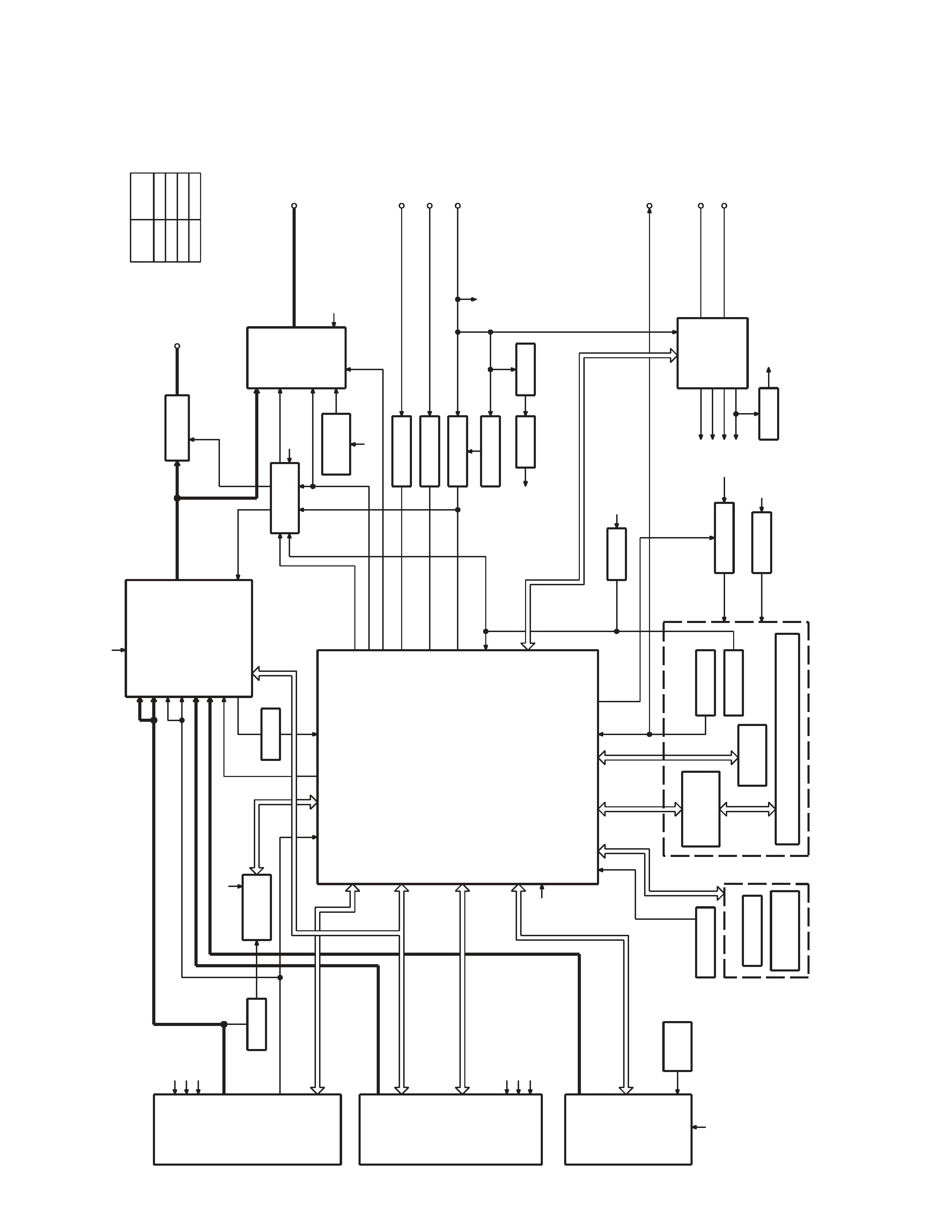
BLOCK
DIA
GRAM
BUFFER
Q101
RDS
DECODER
IC7
Q201
BUFFER
IC1
IC2
REMOCON
RESET SW
ENCODER
ROTARY
S1
WITH
LCD DRIVER
KEY MATRIX
IC1
LCD
PANEL DET
S1
EJECT SW
S1
EJECT ILLUMI
DSI
u-COM
IC2
MPX
E-VOL
&
ACC DET
TEL MUTE
B.U DET
PRE MUTE
DRIVER
MUTE
IC6
POWER
IC
IC4
THERMAL
PROTECT
ACC
TEL MUTE
BACK UP
(REAR)
PRE OUT
SP OUT
SURGE DET
SERVO
SERVO+B
SW 14V
Q21
WIRED REMO
SUPPLY
IC
IC3
POWER
ANT CON
P CON
RESET
IC8
SW 5V
Q4
PANEL 5V
Q152
SW5V
ILLUMI CON
DRIVER
MUTE
S-METER
AUDIO OUT
IFC OUT
PLL-DATA
PLL-CLK
SW5V
AM+B
A8V
LOE/LIM SW
12EJE SW
LOS SW
MS CLK
MS DATA
M MUTE
LO/EJ
M STOP
MOSW
M RST
SERVO+B
A8V
BU5V
LX-DATA C
LX-MUTE
LX-REQ H
LX-REQ C
LX-CLK
LX-CON
LX-DATA H
BACK UP
NOISE
QU
A
L
S-METER
R
D
ATA
R
CLK
FM
AM
MP IN
LEVEL
CD
QUAL
AFS
CH
SW5V
BU5V
P
ANEL
DET
EJECT
DSI
L
CLK
L
D
ATA
S
L
CE
L
D
ATA
L
V
OLUME
A
V
OLUME
B
REMO
ILL
CON
MUTE
P-MUTE
PHONE
ACC DET
B.U DET
BEEP
PS1-0
PS1-1
PS1-2
PS2-0
PS2-2
RST
BU5V
BACK UP
A8V
SW5V
BACK UP
AM+B
ILLUMI
A8V
BU5V
BU5V
BU5V
MODE
CD
FM
AM
CH
LEVEL
3600mV
1372mV
855mV
3600mV
LX-RST
TUNER
CD
CH
SWITCH UNIT (X16- )
DAUGHTER UNIT
(X89- )
KDC-5027/5027Y/508
3
B
B
B
B
A x2
A x2
D
C
E
G
F
H
J
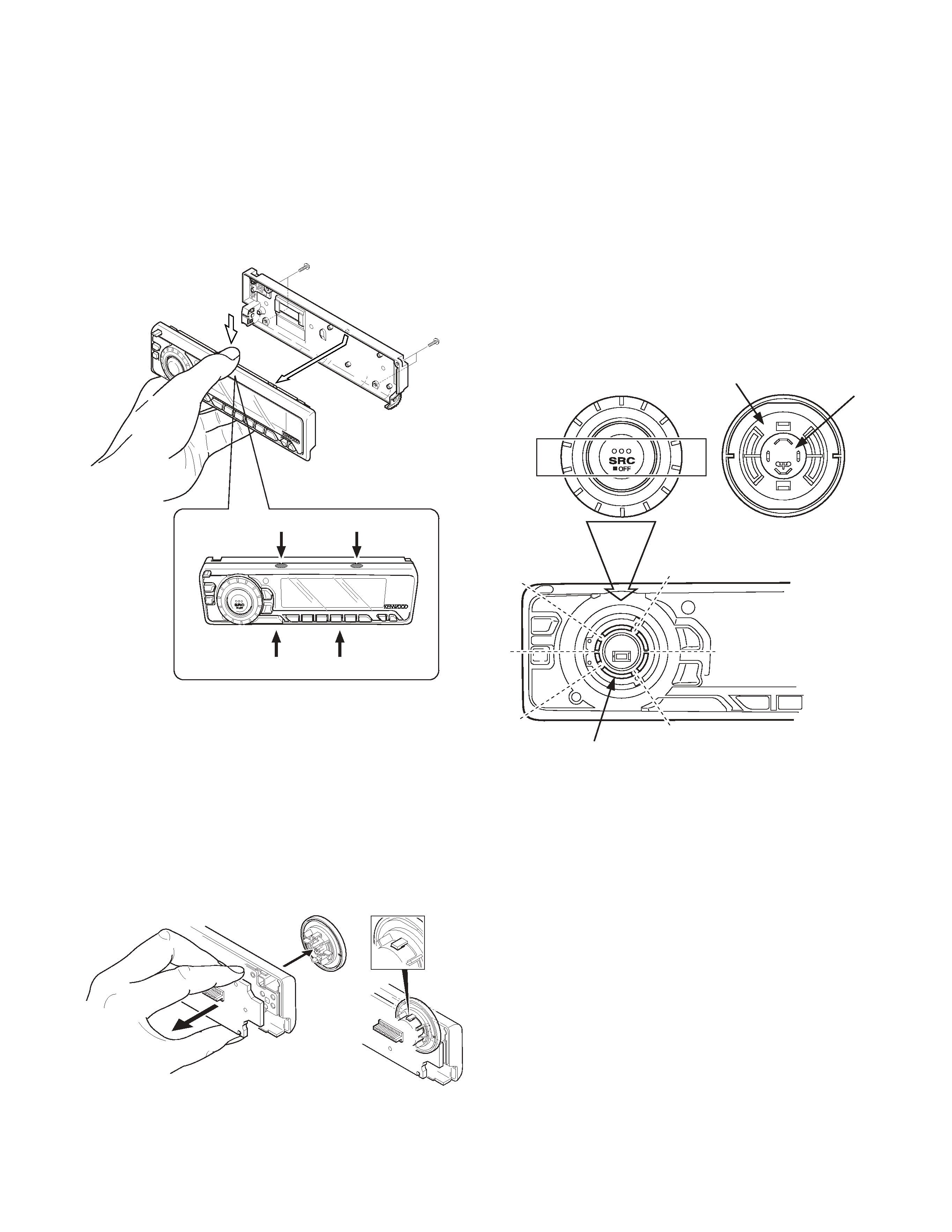
How to Disassemble (PANEL ASSY)
1) Remove four screws (A).
2) While holding the section (B) indicated with arrows, pull and
remove PANEL ASSY.
DISASSEMBLY FOR REPAIR
3) Pull SWITCH UNIT (C) as indicated in the diagram and re-
move knob (D).
(The knob (D) is attached to the rotary with hook (E) and it
is not possible to remove hook (D) only.)
How to install knob (SRC)
1) Place knob (F) and knob (G) in the positions indicated in
the diagram below.
2) While keeping these positions, use a piece of adhesive tape
(H) to hold knobs in position, as shown in the diagarma.
3) Set the rotary (J) position as shown in the diagram.
4) While keeping the letters "SRC" horizontally in position, set
it to the rotary on the panel.
5) Remove the adhesive tape (H).
KDC-5027/5027Y/508
4
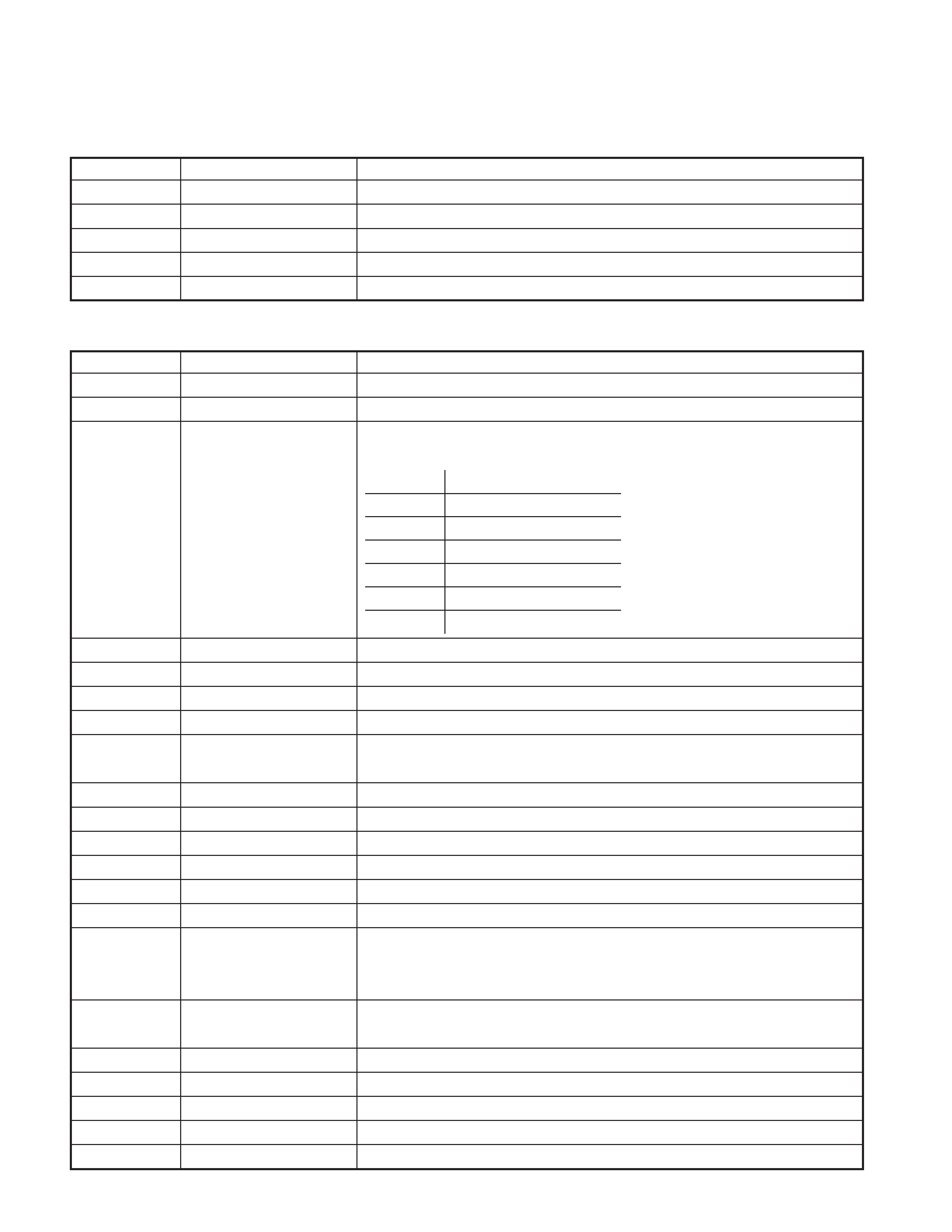
SWITCH UNIT (X16-2502-70)
Ref. No.
Application/Function
Operation/Condition/Compatibility
IC1
LCD Driver
Drives LCD
IC2
Remote Control IC
Controls the unit.
Q1,Q4
REMO ON SW
The power supply of IC2 is turned on when base level goes "L".
Q2
Key Illumination SW (Green)
Lights Green key-illumination when base level goes "H".
Q3
Key Illumination SW (Red)
Lights Red key-illumination when base level goes "H".
ELECTRIC UNIT (X34-3092-70)
Ref. No.
Application/Function
Operation/Condition/Compatibility
IC1
System
µ-COM
Controls FM/AM tuner, the changer, CD mechanism, Panel, volume, and tone.
IC2
E.Vol & N.C.MPX
Controls the source, volume, tone and FM multiplex detector.
Bu5V (5V) Audio8V (8V) FM+B (8V)
AM+B (8V) P-CON ANT-CON
IC3
Power Supply IC
IC4
Power IC
Amplifies the front L/R and the rear L/R to 50W maximum.
IC6
Muting logic IC
Controls logic for muting.
IC7
RDS decoder
IC8
Reset IC
"L" when detection voltage goes below 3.5V or less.
Q1
Surge Detection
"L" when the back-up voltage becomes more than 24V (momentary power down).
"H" when the back-up voltage becomes less than 24V.
Q2
BACK-UP Detection
"L" when B.u is present. "H" when B.u is absent or momentary power down is detected.
Q3
ACC Detection
"L" when Acc is present.
Q4
SW 5V
ON when the base is "L".
Q21
Servo Regurator
Q22
Servo SW
Q101
Composite signal buffer
DSI lights when the base is "L".
Q151
DSI Driver
DSI turns off when the base is "H".
DSI turns on and off when panel is taken off.
Q152
Panel 5V SW
When the panel is attached, the base goes "L", turning the Tr ON to supply 5V to the panel.
When panel is taken off, panel 5Vcut off.
Q153,Q154
ILLUMI Control
ILLUMI lights when the base of Q153 is "H".
Q201
Noise buffer
Q351
Pre Mute SW
Mutes the Rear Lch when the base is "H".
Q352
Pre Mute SW
Mutes the Rear Rch when the base is "H".
Q354
Pre Mute SW
Drives the Pre Mute sw (Q351, 352) when the base is "L".
COMPONENTS DESCRIPTION
SW1
OUT
1.5~3.0
Audio ON
3.5~5.0
Audio P-CON ON
7.0~
Audio P-CON P-ANT ON
SW2
2.0~3.0
ILLUMI FM ON
4.0~
ILLUMI AM ON
KDC-5027/5027Y/508
5
MICROCOMPUTER'S TERMINAL DESCRIPTION
Pin No.
Pin Name
I/O
Application
Truth Value
Processing Operation Description
Table
1~5
N.C
O
OPEN (Output L fixed)
6
REMO
I
Remote control input
7
N.C
O
OPEN (Output L fixed)
8
BYTE
I
External data bus width switching input
Connect to GND
9
CNVSS
I
Pull down at 1k
10
XCIN
I
Sub clock input
11
XCOUT
O
Sub clock output
12
RESET
I
Reset input
Normal : H, When RESET : L
13
XOUT
O
Main clock output
14
VSS
-
GND
15
XIN
I
Main clock input
16
VCC
-
Power supply input (5V)
17
NMI
Pull up (B.U5V)
18
EJECT
I
EJECT detection input
L : EJECT
19
R-CLK
I
RDS decoder CLK input (RDS model only)
20
LX-REQ S
I
Reception request from external slave
L : Request
21
ILL CON
O
Illumination output control
FLIP DET "L" during "H"
22
PANEL 5V
I/O
Panel 5V control
L : ON (Panel detect & ACC ON)
Hi-Z : OFF (Panel no detect or ACC OFF)
23
VOL A
I
VOL key input
24
VOL B
I
VOL key input
25
LOE/LIM SW (SW3)
I
CD DOWN SW detection
H : Chucking
26
BEEP
O
BEEP output
27
M STOP
O
STOP request to CD mechanism
When CD : H, When STOP : L
28
MOSW
O
CD mechanism MOTOR SW
LOADING, EJECT, Brake : H
29
PLL-CLK
I/O
Clock output to F/E
30
PLL-DATA
I/O
Data input/output with F/E
31
LX-DATA M
O
Data output to external slave
Last retention
32
LX-DATA S
I
Data input from external slave
33
LX-CLK
I/O
Clock input and output of external slave
34
LX-REQ M
O
Transmission request to external slave
At request : L
35
L DATAS
O
Data output to LCD driver
36
L DATAL
I
Data input from LCD driver
37
L CLK
I/O
Clock output to LCD driver
38
FLIP-DET
I
Panel collapse detection
L : Panel received, H : Panel collapse
39
L CE
O
CE output to LCD driver
40
LO/EJ
I/O
CD mechanism LOADING, EJECT switching
STOP, Brake : Hi-z
LOADING : L, EJECT : H
41
EPM
I
For flush writing
Pull down at 100k
SYSTEM MICROCOMPUTER : M30302MC-1N4FP (X34 : IC1)