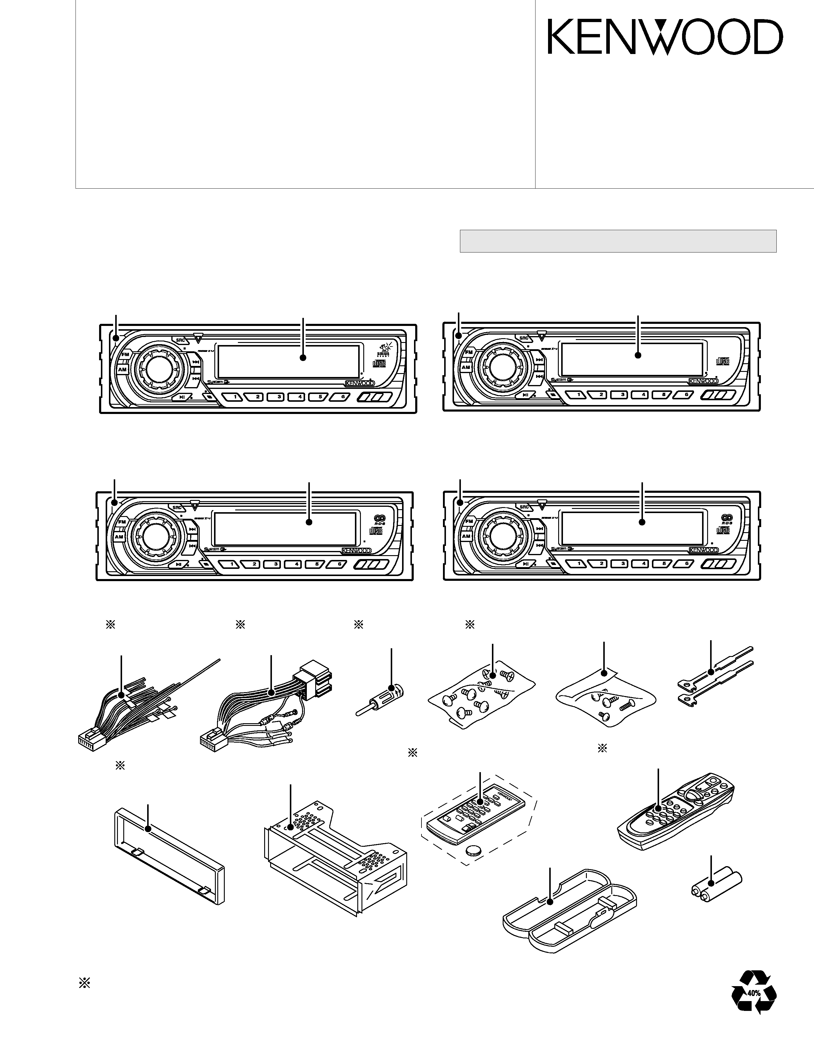
KDC-3022
OFF
-
+
M.RDM
REP
SCAN
RDM
AUD
C.S.
MENU
NAME.S
DISP
AUTO
AME
KDC-5023
OFF
-
+
DAB
M.RDM
REP
SCAN
RDM
AUD
PTY
MENU
NAME.S
DISP
AUTO
AME
KDC-5024
OFF
-
+
DAB
M.RDM
REP
SCAN
RDM
AUD
PTY
MENU
NAME.S
DISP
TI
KDC-507
OFF
-
+
DAB
M.RDM
REP
SCAN
RDM
AUD
PTY
MENU
NAME.S
DISP
TI
Escutcheon
(B07-3022-02)
(B07-3083-02)
(B07-3089-02)
Plastic cabinet assy
(A02-1486-13)
Mounting hardware assy
(J21-9716-03)
DC cord
(E30-4790-05)
(E30-6134-05)
Antenna adaptor
(T90-0523-05)
Screw set
(N99-1730-15)
Lever
(D10-4589-04)
DC cord
(E30-4784-05)
(E30-6131-05)
Remote controller assy(RC-505)
(A70-2040-05)
Screw set
(N99-1719-05)
Not supplied
Panel assy
(A64-2824-02 : KDC-3022)
(A64-2825-02 : KDC-322)
Front grass
(B10-4304-01 : KDC-3022)
(B10-4305-01 : KDC-322)
Panel assy
(A64-2838-02 : KDC-5024/Y)
(A64-2851-02 : KDC-5024V/YV)
Front grass
(B10-4314-01 : KDC-5024/Y)
(B10-4324-01 : KDC-5024V/YV)
Panel assy
(A64-2833-02 : KDC-5023R)
(A64-2834-02 : KDC-5023)
Front grass
(B10-4310-01 : KDC-5023R)
(B10-4311-01 : KDC-5023)
Panel assy
(A64-2839-02 : KDC-5094RY)
(A64-2842-02 : KDC-507)
Front grass
(B10-4315-01 : KDC-5094RY)
(B10-4317-01 : KDC-507)
Remote controller assy(RC-410)
(A70-2025-05)
Depends on model. Refer to the parts list.
·CD MECHANISM OPERATION DESCRIPTION is not in this sevice manual.
Please refer to service manual for X92-4450-0X (B51-7889-00).
CD mechanism extension cord (22PIN) : W05-0618-00
© 2003-1 PRINTED IN JAPAN
B53-0024-00 (N) 3379
CD RECEIVER
KDC-3022, 322
KDC-5023/R, 5024/V/Y/YV
KDC-507, 5094RY
SERVICE MANUAL
KDC-3022,322,5023/R,5024/V/Y/YV
,507,5094R
Y
2
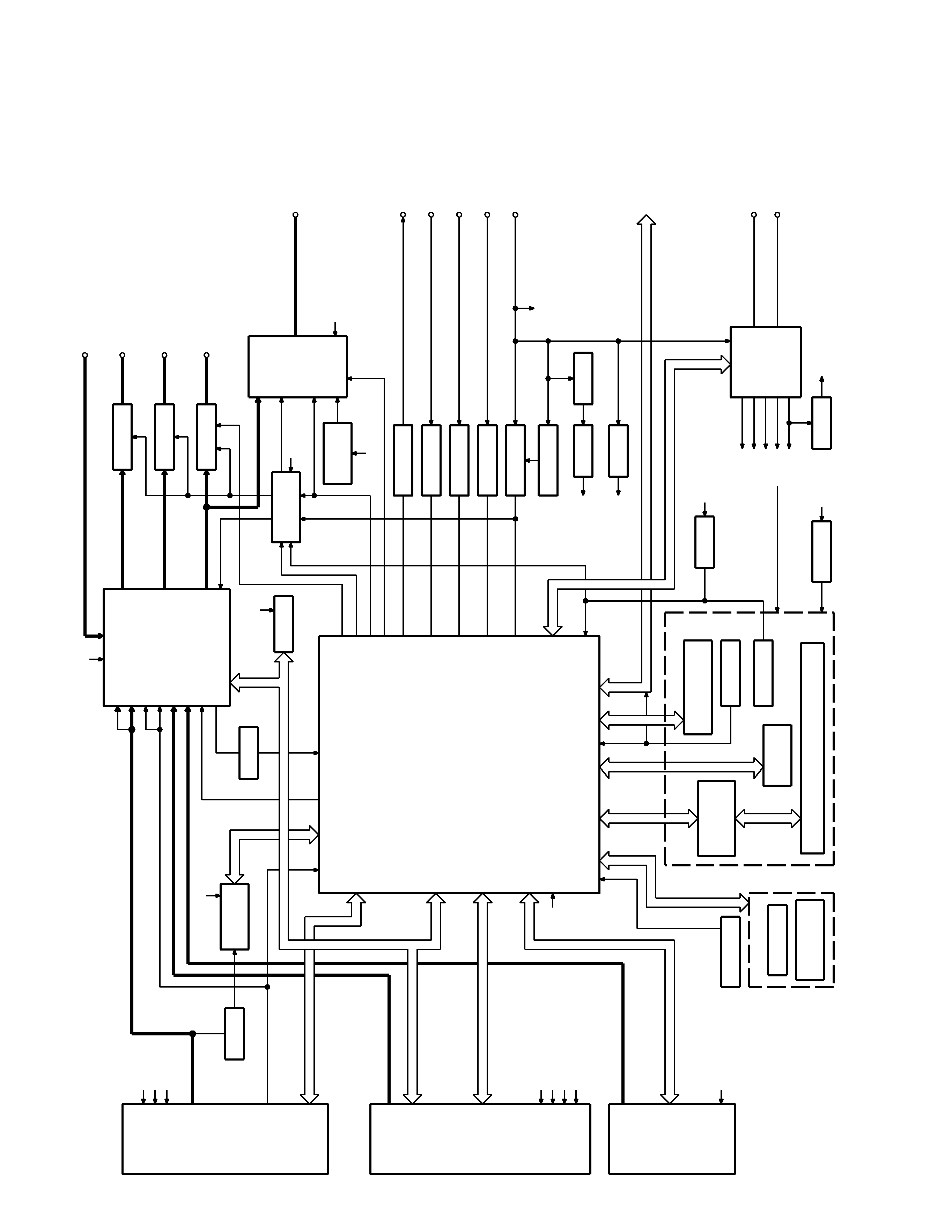
BLOCK
DIAGRAM
BUFFER
Q101
RDS
DECODER
IC7
Q201
BUFFER
EEPROM
IC10
IC1
(V-ILL ONLY)
DA CONVERTER
IC3
IC2
REMOCON
RESET SW
ENCODER
ROTARY
S24
WITH
LCD DRIVER
KEY MATRIX
IC1
LCD
PANEL DET
S1
EJECT SW
S1
EJECT ILLUMI
DSI
u-COM
IC2
MPX
E-VOL
&
EXT AMP
DIMMER
ACC DET
TEL MUTE
B.U DET
PRE MUTE
PRE MUTE
PRE MUTE
DRIVER
MUTE
IC6
POWER
IC
IC4
THERMAL
PROTECT
PRE OUT
(REAR/NF)
EXT.AMP.CON
DIMMER
ACC
TEL MUTE
BACK UP
AUX IN
(REAR) 3PRE
PRE OUT
(FRONT)
PRE OUT
SP OUT
SURGE DET
SW REG
CD MECHA+B
SERVO
SERVO+B
SW 14V
Q21
IC9
OPEL DISP I/F
WIRED REMO/
SUPPLY
IC
IC3
POWER
ANT DET
P CON
RESET
IC8
SW 5V
Q4
PANEL 5V
Q152
SW5V
S-METER
AUDIO OUT
IFC OUT
PLL-DATA
PLL-CLK
SW5V
AM+B
A8V
SW3
SW2
SW1
MS CLK
MS DATA
M MUTE L
SW4
M MUTE R
LO/EJ
M STOP
MOSW
M RST
SERVO+B
A8V
BU5V
CD MECHA+B
DATA C
CH MUTE
CH RST
REQ H
REQ C
CH CLK
CH-CON
DATA H
BUCK UP
NOISE
QUAL
S-METER
R
DA
T
A
R
CLK
FM
AM
MP IN
LEVEL
CD
QUAL
AFS
CH
SW5V
SW5V
BU5V
P
ANEL
DET
EJECT
DSI
L
CLK
L
D
ATA
S
L
C
E
L
D
ATA
L
VOL
A
VOL
B
REMO
V
DA
T
A
V
CLK
O-CE
O-DA
T
A
O-CLK
PRE MUTE
MUTE
P-MUTE
EXT.AMP.CON
DIMMER
PHONE
ACC DET
B.U DET
BEEP
PS1-0
PS1-1
PS1-2
PS2-0
PS2-2
RST
FREE
REAR
FRONT
BU5V
BUCK UP
A8V
AUX
SW5V
BACK UP
AM+B
FM+B
ILLUMI
A8V
BU5V
BU5V
BU5V
TUNER
CD
EX.CH
SWITCH UNIT (X16- )
DAUGHTER UNIT
(X89- )
KDC-3022,322,5023/R,5024/V/Y/YV,507,5094RY
3
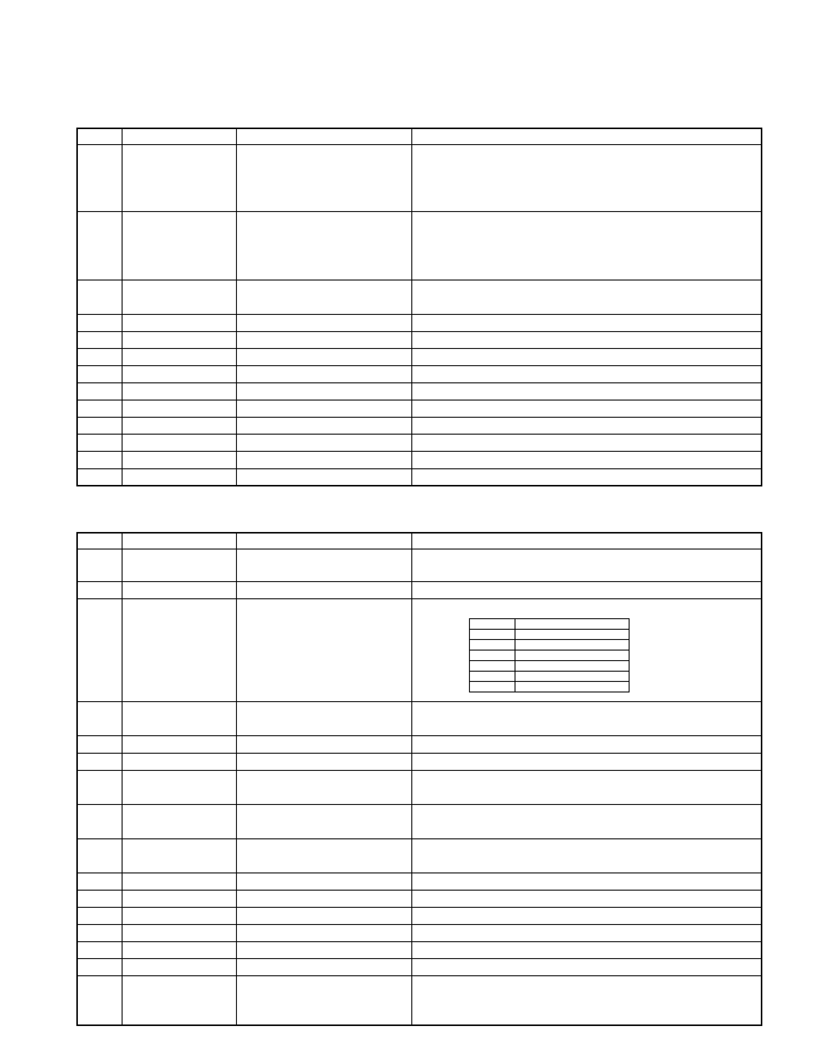
q CD PLAYER UNIT (X32-5390-00/01)
COMPONENTS DESCRIPTION
Ref.No.
Component Name
Application/Functions
Operation/Condition/Compatibility
IC1
AN22002AA
RF amplifier adapted for CD-RW
Generation of RF signal based on the signals from the APC circuit and
pickup, and generation of servo error (focusing error and tracking error)
signals. Detection of dropout, anti-shock, track crossing and off-track
conditions, included gain control function during CD-RW.
IC2
MN6627771KP
CD signal processor built-in MI-COM
Focusing, tracking, sled and spindle servo processing. Automatic
adjustment (focusing, tracking, gain, offset and balance) operations.
Digital signal processing (DSP, PLL, sub-codes, CIRC error correction,
audio data Interpol ration) operations, and Microcomputer function.
IC3
BA5824FP
4CH BTL driver
Focusing coil, tracking coil, spindle motor and sled motor driver, disc
loading and eject operation.
IC4
NJM4580M1
Low pass filter
2nd low pass filter for audio signals
Q1
MCH6101
APC
LD power control
Q2
2SA1362(Y)
D.5V SW
When P ON signal gose"L", Q2 is ON
Q3
DTC124EUA
Q4 SW
When P ON signal gose"L"(SW+5V AVR is ON), Q3 is ON
Q4
DTA143XUA
A.8V SW
When P ON signal gose"L"(Q3 is ON), Q4 is ON
Q5
2SC4081
Current driver
Current driver
Q6
2SA1576A
Current driver
Current driver
D1
DAN202U
Protection diode
Laser diode protection
D2
MA8051-L
Zener diode
DAC AVR/LPF reference voltage (A.5V)
D3
DA204U
Current driver
Current driver
q ELECTRIC UNIT (X25-9580-xx/2232-xx)
Ref.No.
Component Name
Application/Functions
Operation/Condition/Compatibility
IC1
M30302MC-5W3FP
System microcomputer
Control for TUNER unit, CD mechanism, volume & tone, LCD driver and
M30302MC-1N4FP
external CD changer unit
IC2
TDA7407D
Electronic volume & N.C.MPX
Control for source selector, volume & tone, and FM multiplex detector.
IC3
BA4911-V4
Power supply IC
Power supply for the units (Bu5V, Audio8V, FM+B, AM+B, P-con and
ANT-con)
IC4
TA8273H
Audio power amp IC
Amplifier for audio signal to derive for 4channel speakers (50W
maximum for each channel)
IC6
HD74HC27FP
Muting control IC
Control for timing for mute
IC7
SAA6581T
RDS decoder
Decode for RDS signal
IC8
PST3435UL
Reset IC
When detection voltage goes below 3.5V or less Reset IC output change
to "L" signal
Q1
2SC4081
Serge detection
When backup voltage become more than 24V output is "L" (momentary
power down) / When backup voltage become less than 24V output is "H"
Q2
2SC4081
Backup detection
When BU voltage supplied output is "L" / When BU voltage not supplied
or momentary power down is detected output is "H"
Q3
2SC4081
ACC detection
When ACC voltage supplied output is "L"
Q4
2SA1036K
SW 5V
When base voltage is "L" Q4 is ON
Q21
2SD2375
AVR
Servo regulator
Q22
UMC2N
SW
Servo SW
Q23
UMC2N
IC control
Power supply IC controller
Q101
KRC410
Buffer amp
COMPOSITE SIGNAL BUFFER
Q151
DTA114YUA
DSI driver
When base voltage level is "L" DSI LED is light up / When base voltage
level is "H" DSI LED turns off / When panel assy is pull off, cut off the
supply to panel 5V AVR.
SW1
OUT
1.5-3.0V
Audio ON
3.5-5.0V
Audio, P-con ON
7.0V-
Audio, P-con, P-ant ON
SW2
2.0-3.0V
Illumination, FM ON
4.0V-
Illumination, AM ON
KDC-3022,322,5023/R,5024/V/Y/YV,507,5094RY
4
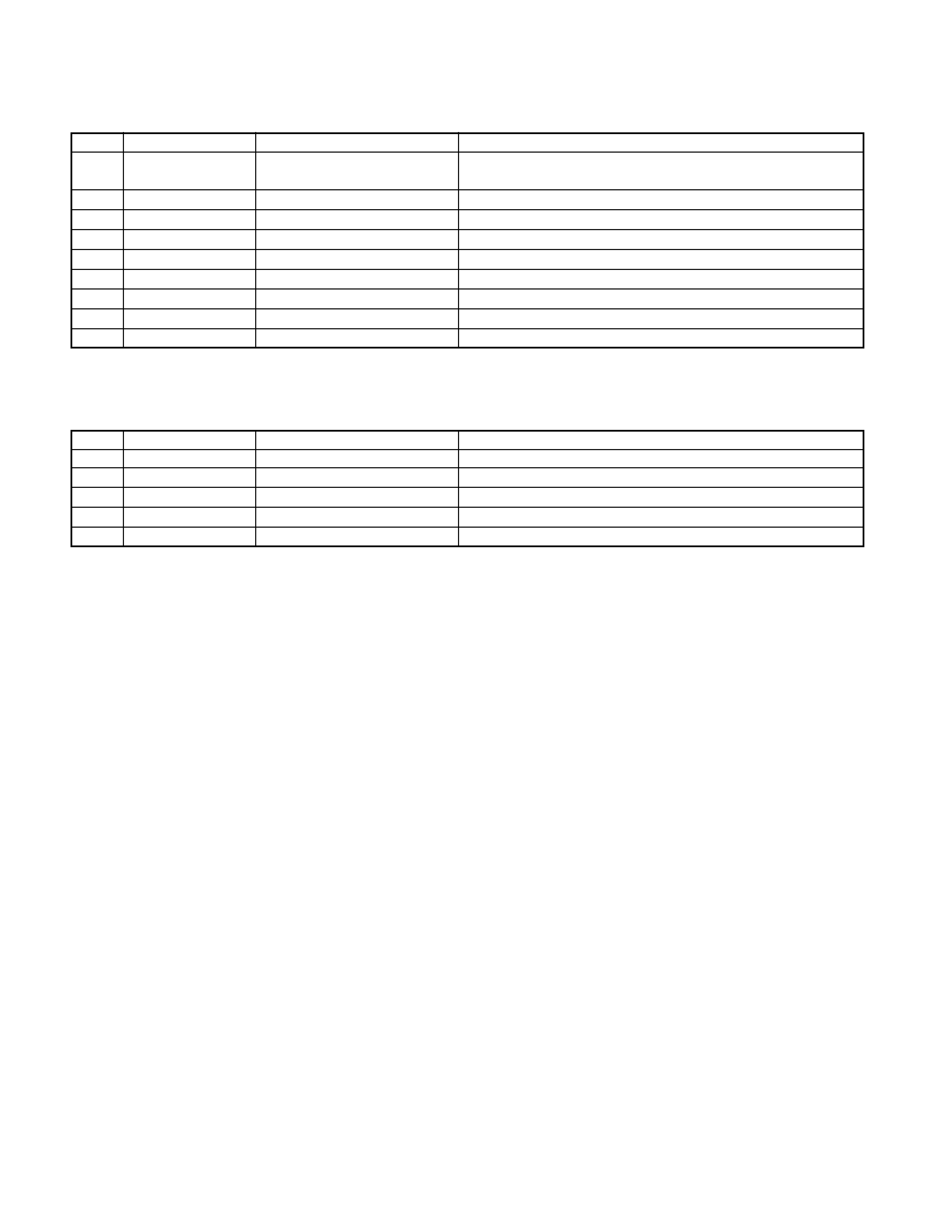
COMPONENTS DESCRIPTION
Ref.No.
Component Name
Application/Functions
Operation/Condition/Compatibility
Q152
2SA1576A
Panel 5V SW
When panel assy attached to the unit, Q152 base gose "L" and supply to
panel 5V AVR to panel assy
Q153
KRC404
Illumination control
When Q153 base voltage to "H", illumination is light up
Q154
2SA1577
Illumination control
When Q153 base voltage to "H", illumination is light up
Q201
KRC410
Buffer amp
Noise buffer amp
Q351
KRC410
Pre mute SW
When base voltage to "H", muting to the rear Lch line
Q352
KRC410
Pre mute SW
When base voltage to "H", muting to the rear Rch line
Q354
KRA303
Pre mute SW
When base voltage to "L", drive to pre mute SW(Q351,352,355,356)
Q355
KRC410
Pre mute SW
When base voltage to "H", muting to the front Lch line
Q356
KRC410
Pre mute SW
When base voltage to "H", muting to the front Rch line
q SWITCH UNIT (X16-203x-xx/2032-xx)
Ref.No.
Component Name
Application/Functions
Operation/Condition/Compatibility
IC1
NJU6535
LCD driver
Drive for LCD unit
IC2
PNA4S22M
Remote control IC
Receiving for the remote control unit
Q1,Q4
DTA114EUA
Remo.on SW
When base voltage level goes "L" the power supply IC2 is turned "ON"
Q2
2SC4081
Key illumination SW
Lights up for green key illumination when base voltage level goes "H"
Q3
2SC4081
Key illumination SW
Lights up for red key illumination when base voltage level goes "H"
KDC-3022,322,5023/R,5024/V/Y/YV,507,5094RY
5
MICROCOMPUTER'S TERMINAL DESCRIPTION
Pin No.
Name
I/O
Description/Processing Operation
1-5
N.C
-
Open
6
REMO
I
Remote control signal input terminal
7
N.C
-
Open
8
BYTE
I
EXT. bus width select input terminal (GND)
9
CNVSS
-
Pull down to GND
10
XCIN
I
Sub clock input terminal (32.768KHz)
11
XCOUT
O
Sub clock output terminal (32.768KHz)
12
RESET
I
Reset terminal (Active : L )
13
XOUT
O
Main clock output terminal (10MHz)
14
VSS
-
GND
15
XIN
I
Main clock input terminal (10MHz)
16
VCC
-
Power supply input terminal (BU 5V)
17
NMI
-
Pull up to BU5V
18
EJECT
I
Eject detection terminal (Active L)
19
R-CLK
I
RDS decoder clock input terminal
20
LX-REQ S
I
EXT. unit request signal input terminal (Request L)
21
ILL CON
O
Illumination control terminal
22
PANEL 5V
O
Control for Panel5V AVR (Active L)
23
VOL A
I
Volume key input terminal
24
VOL B
I
Volume key input terminal
25
LOE/LIM SW
I
CD mechanism down sw detect input terminal (Disc clamp : H)
26
BEEP
O
Beep audio signal output terminal
27
M STOP
O
Request signal (Mechanism is STOP) output to CD mechanism (active L)
28
MOSW
O
CD mechanism motor control output terminal (Loading, eject ,brake : H)
29
PLL-CLK
O
System clock put to Front-end
30
PLL-DATA
I/0
Data input / out put to Front-end
31
LX-DATA M
O
EXT. unit Data output to EXT.unit
32
LX-DATA S
I
EXT. unit Data input from EXT.unit
33
LX-CLK
I/O
EXT.unit Clock input/output terminal
34
LX-REQ M
O
EXT unit Request output terminal (Request L)
35
L DATAS
O
DATA output terminal to LCD driver IC
36
L DATAL
I
DATA input terminal from LCD driver IC
37
L CLK
O
CLK output terminal to LCD driver IC
38
FLIP-DET
I
Panel assy open detect terminal (panel close : L )
39
L CE
O
CE output for LCD driver IC
40
LO/LE
I/O
CD mechanism loading / eject control terminal
41
EPM
I
Flash memory control terminal (pull down to GND, 100K)
42
M RST
O
Reset signal output to CD mechanism (active L)
43
M-MUTE R
I
Request to muting signal(R ch) from Mechanism ( Mute on : L )
44
12EJE SW
I
12cm CD disc eject SW detection input terminal (12cm disc : L )
45
M-MUTE L
I
Request to muting signal (L ch) from Mechanism ( Mute on : L )
46
LX-CON
O
EXT.unit select control terminal (Active H)
47
LO.S SW
I
Loading start SW detection input terminal (Loading start : L )
48
DSI
I
Disc guide illumination control terminal (Lighting on : L)
49
PANEL DET
I
Panel assy detect terminal (Panel assy come off : L)
50
N.C
-
Open
q IC1: ELECTRIC UNIT (X25-9580-xx/2232-xx)