© 2000-12 PRINTED IN JAPAN
B51-7701-00(S) 1752
SERVICE MANUAL
CD RECEIVER
KDC-216S/2018
CRSC
ADJ
KDC-216S
AUD
PWR OFF
LOUD
SCAN
RDM
REP
AME
AUTO
COMPACT
DIGITAL AUDIO
45Wx4
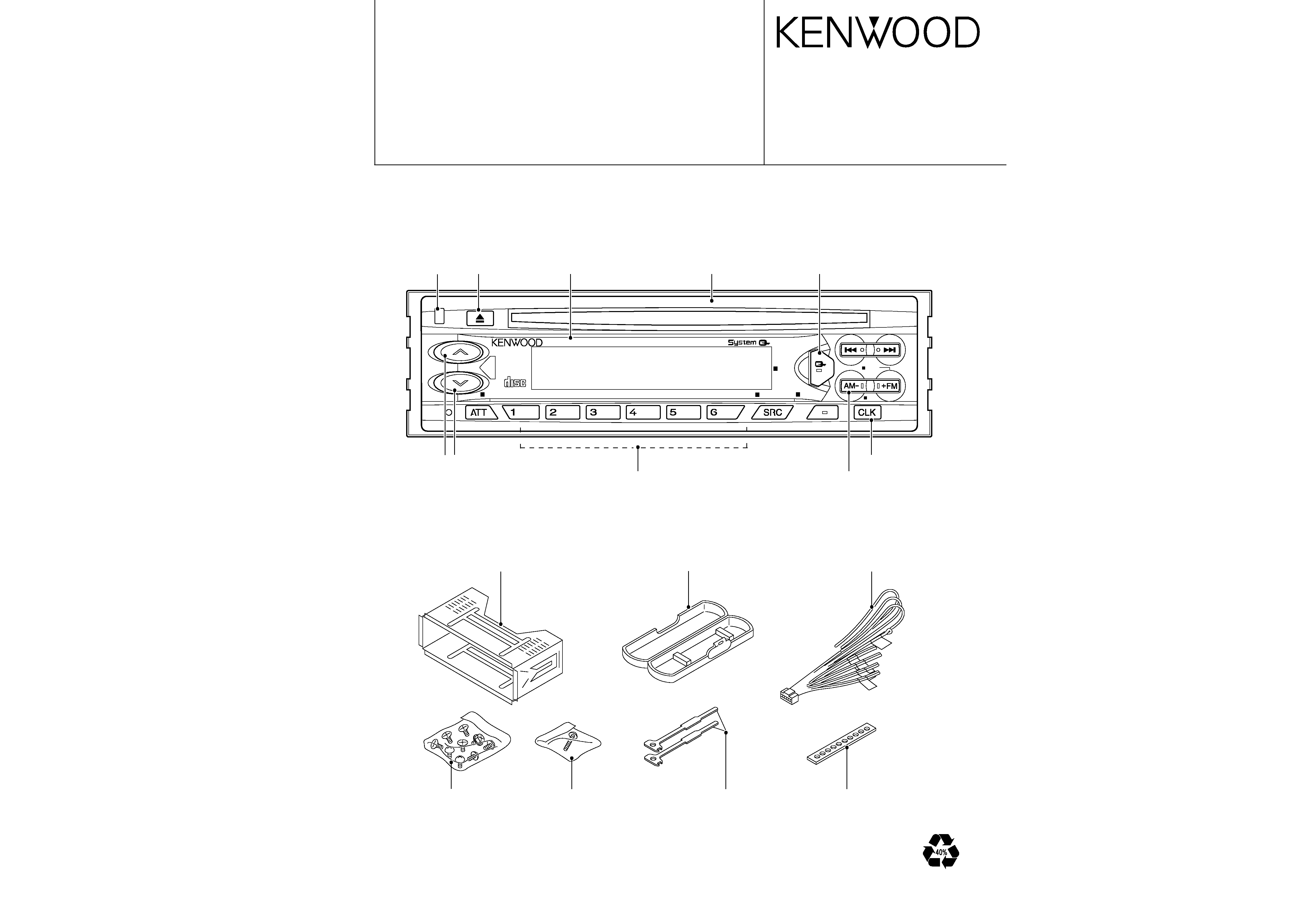
Knob(RELEASE)
(K24-3665-04)
Knob(EJ)
(K24-3653-04)
Front glass
(B10-3294-01:216S)
(B10-3297-01:2018)
Panel assy
(A64-2202-02:216S)
(A64-2209-02:2018)
Knob (Q)
(K24-3652-04)
Knob(VOL)
(K25-1256-03)
Knob(1-6)
(K25-1253-03)
Knob(CLK)
(K25-1254-03)
Knob(FM/AM)
(K25-1255-03)
DC cord
(E30-4783-05:216S)
(E30-4784-05:2018)
Plastic cabinet assy
(A02-1486-13)
Mounting hardware assy
(J21-9641-03)
Stay
(J54-0606-04)
Screw set
(N99-1610-15)
Lever
(D10-4589-04)
Screw set
(N99-1632-05)
q KDC-216S
KDC-216S/2018
2
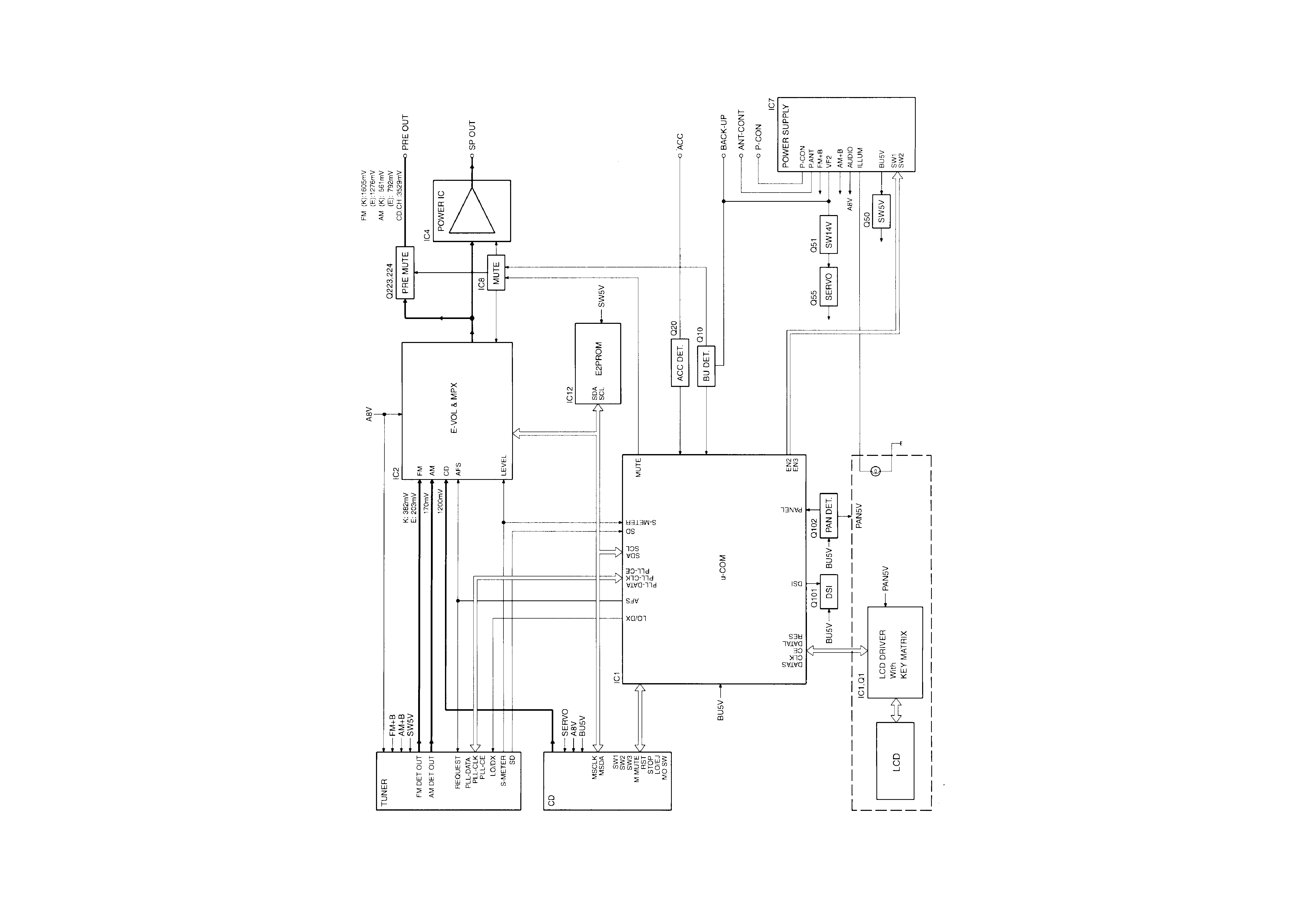
BLOCK DIAGRAM
KDC-216S/2018
3
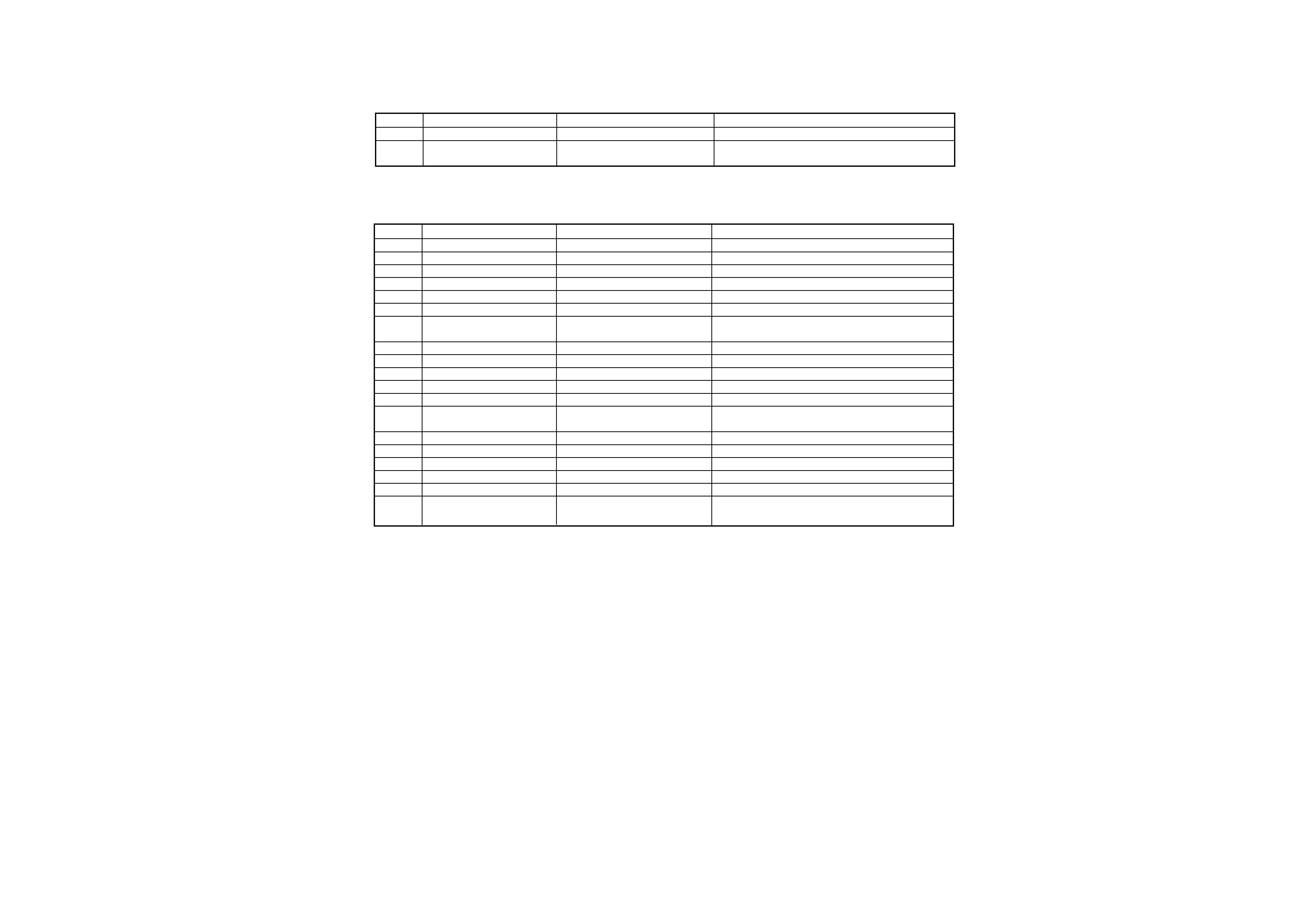
COMPONENT DESCRIPTION
qSWITCH UNIT(X13-9880-13)
Ref.No.
Component Name
Application/Function
Operation/Condition/Compatibility
IC1
LC75853NE
LCD driver
Ready on key-matrix
Q1
DTA114EK or KRA102S or
key-matrix permission SW
Ready on key-matrix, ON when the base goes "Lo"
UN2111
qELECTRIC UNIT(X25-8690-XX)
Ref.No.
Component Name
Application/Function
Operation/Condition/Compatibility
IC1
UPD780058GC231
System
µ-COM.
IC2
TDA7407D
E-VOL. & N.C. MPX
IC4
TDA7386
Power IC
IC7
BA4911-V4
Power supply IC
IC8
HD74HC27FP
Mute gate IC
3 input NOR gate x3
IC11
S-80830ANNP
RESET IC
Detection voltage 3.0V
IC12
BR24C01AF or BR24C01AF-W
E2PROM
M24C01-WMN6T or S-24C01B
Q10
2SC4081 or 2SD1819A
B.U. detection
Detect BU voltage
Q20
2SC4081 or 2SD1819A
ACC detection
Detect ACC voltage
Q40
DTA124EUA or UN5112
PREOUT mute driver
Mutes when base is "Lo" (controls Q221-224)
Q50
2SA1036K
SW 5V
ON when the base is "Lo".
Q51
UMC2N
SW 14V
ON when the base is "Hi" (controls Q55)
Q53
UMC2N
Switch for power supply IC
ON when the base is "Hi" (controls SW1 pin of power
supply IC)
Q55
2SD2375 or 2SD2396
AVR for SERBO +B
Output issued when SW14V is on (base is "Hi")
Q70
2SC4081 or 2SD1819A
SURGE detection
Detect SURGE voltage
Q101
2SC4081 or 2SD1819A
DSI SW
DSI LED turns ON when base is "Hi"
Q102
DTA114YUA or UN5114
PANEL 5V SW
ON when the base is "Lo"
Q223,224 DTC143TUA or UN5216
PREOUT MUTE
Mute applied to PREOUT (output) when base is "Lo"
Q251
DTC114YUA or UN5214
Power IC SVR SW
Turns ON when base is "Hi" and capacitor on SVR
pin discharges
KDC-216S/2018
4
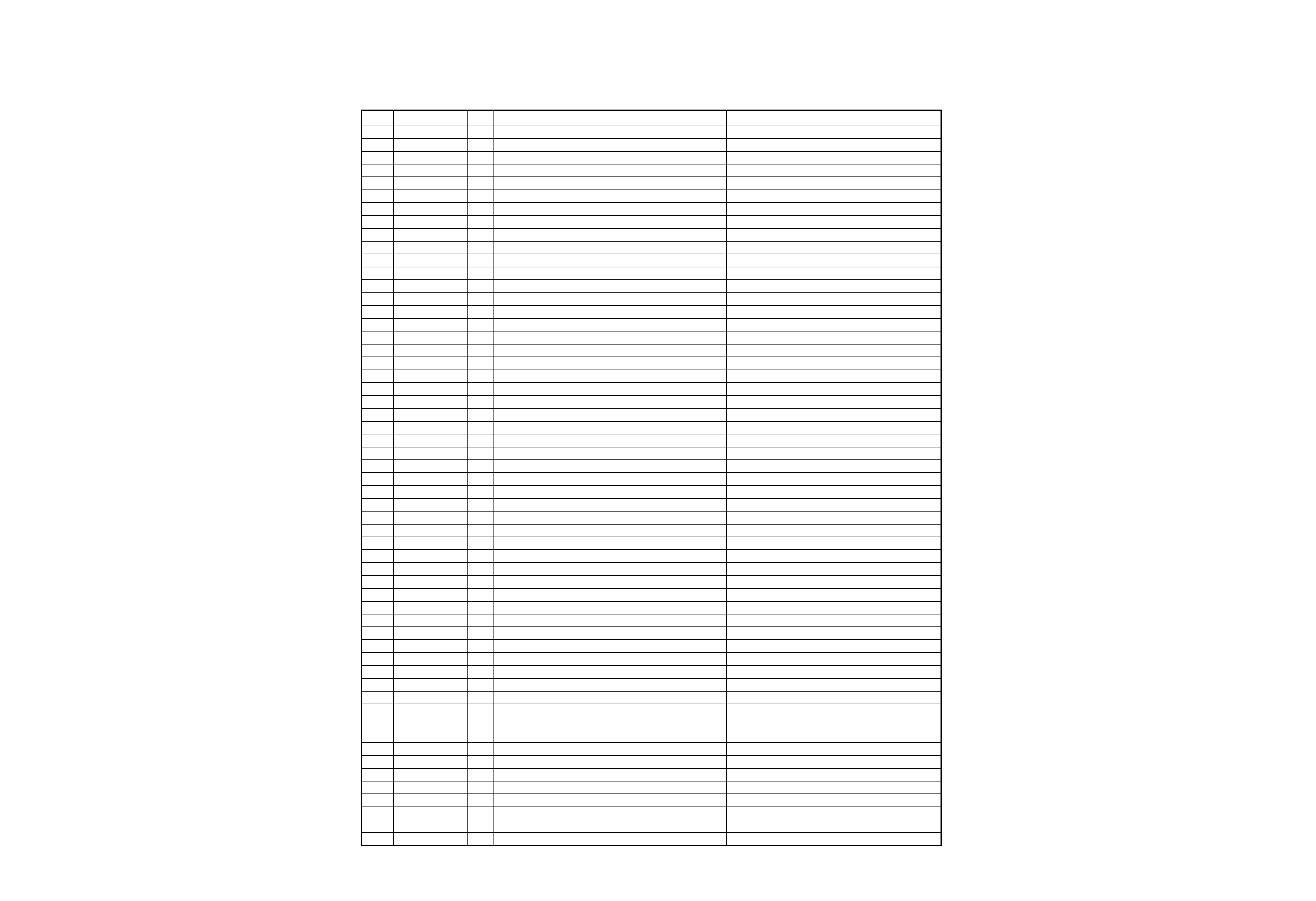
MICROCOMPUTER'S TERMINAL DESCRIPTION
qTerminal Description
Pin
Function
I/O
Description
Processing Operation
1
AV CONT
O
A/D converter reference voltage control output
"Hi": ON / "Lo": OFF
2
IC2 TYPE0
I
IC2 setting terminal
"Lo": Initial value
3
IC2 TYPE1
I
IC2 setting terminal
"Lo": Initial value
4
AVSS
-
Ground connection terminal
connected to GND
5
M MUTEL
I
Muting request from the MICOM. of CD mecha.
"Lo": Mute request
6
N.C
O
Not used
7
AVREF1
I
D/A converter reference voltage input
8
ILLUMI
O
Illumination AVR ON/OFF control output
"Hi": AVR ON
9
L RES
O
Reset output to the LCD driver IC
"Lo": Reset
10
PANEL
I
Panel open/close detection input
"Lo": Panel closed
11
L DATAL
I
Data input from the LCD driver IC
12
L DATAS
O
Data output to the LCD driver IC
13
L CLK
O
Clock output to the LCD driver IC
14
N.C
O
Not used
15
N.C
O
Not used
16
CH-DATAC
I
Data input from changers
17
CH-DATAH
O
Data output to changers
18
CH-CLK
I/O
Clock input/output with changers
19
L CE
O
CE output to the LCD driver IC
"Hi": Active
20
N.C
O
Not used
21
M RST
O
Reset output to the MICOM. of CD mecha.
"Lo": Reset
22
M STOP
O
Stop request to the MICOM. of CD mecha.
"Lo": Stop
23
MOSW
O
CD mechanism loading motor control output
"Hi": Loading & Eject / "Lo": other
24
PLL SCL
O
Clock output to the tuner pack
25
AM+B
O
AM+B control
"Hi": during AM reception
26
FM+B
O
FM+B control
"Hi": during FM reception
27
M-SCL
I/O
Clock input/output with the MICOM. of CD mecha.
28
DSI
O
DSI output
"Hi": LED ON
29
LO/EJ
I/O
CD mecha.Loading/Eject switching output
"Lo": Loading / "Hi": Eject
30
SW3
I
Down & limit switch detection input
"Hi": Chucking / "Lo": Pickup most inner position
31
R DATA
I
Data input from RDS decoder
32
R QUAL
I
Quality input from RDS decoder
33
VSS1
-
Ground connection terminal
connected to GND
34
SD
I
SD input from the tuner pack
"Hi": Station detected
35
IC2 SCL
O
Clock output to the E-VOL. IC
36
M-SDA
I/O
Data input/output with the MICOM. of CD mecha.
37
PLL SDA
I/O
Data input/output with the tuner pack
38
IC2 SDA
I/O
Data input/output with the E-VOL. IC
39
MUTE
O
Mute control output
"Hi": Mute ON / "Lo": Mute OFF
40
N.C
O
Not used
41
AFC
O
AFC control output
"Lo": during FM seek
42
CH-REQH
O
Request output to changers
"Lo": Request
43
CH-CON
O
Changer control
"Lo": Standby / "Hi": ON
44
N.C
O
Not used
45
P MUTE
O
Power IC mute control
"Lo": Mute
46
SVR
O
Power lC reset terminal
When the momentary power down, after ACC
OFF/ON is detected and after POWER ON/
OFF, the output goes "Hi" temporarily.
47
STBY
O
Power IC standby control output
"Hi": POWER ON mode
48
P CON
O
Power control
"Hi": POWER ON mode except ALL OFF mode
49
P ANT
O
Antenna control
"Hi": during FM/AM reception
50
BEEP
O
BEEP sound output
51
ACC DET
I
ACC detection input
"Hi": ACC OFF / "Lo": ACC ON
52
BU DET
I
Momentary power down detection input
"Hi": When momentary power down detected
or BU OFF / "Lo": BU ON
53
N.C
O
Not used
5
6
KDC-216S/2018
MICROCOMPUTER'S TERMINAL DESCRIPTION
KDC-216S/2018
ADJUSTMENT
Pin
Function
I/O
Description
Processing Operation
54
N.C
O
Not used
55
N.C
O
Not used
56
SW5
O
SW 5V control
"Lo": POWER ON mode
57
P ON
O
Microprocessor peripheral power supply control terminal
"Hi": ACC ON or during CD Loading/Eject
58
TYPE2
I
Destination type input terminal 2
59
N.C
O
Not used
60
RESET
I
Reset input terminal
"Lo": System reset
61
REMO
I
Data input from the remote control light sensor
62
R CLK
I
Clock input from RDS decoder
63
CH-REQC
I
Request input from changers
"Hi": Request
64
SW1
I
Loading detection
"Lo": CD chucking
65
KEY-REQ
I
Key request terminal
"Lo": Request
66
SW2
I
12cm disc detection terminal
"Lo": 12cm disc
67
VSS0
-
Ground connection terminal
connected to GND
68
VDD1
-
VDD connection terminal
69
X2
-
Main clock resonator connection terminal
70
X1
I
Main clock resonator connection terminal
71
IC(TEST)
-
Not used
connected to GND
72
XT2
-
Sub clock resonator connection terminal
N.C.
73
N.C
I
Sub clock resonator connection terminal
connected to BU5V lines
74
VDD0
-
VDD connection terminal
75
AVREF0
I
A/D converter reference voltage input
76
SMETER
I
S-meter input from the tuner pack
77
PHONE
I
PHONE detection input
1V or less: TEL MUTE,2.5V or greater: NAVI MUTE
78
NOISE
I
Noise detection input
79
TYPE0
I
Destination type input terminal 0
80
TYPE1
I
Destination type input terminal 1
Test Mode
1. How to enter test mode
While holding the FM key and preset 6 key, reset the unit.
All display segments light up when the test mode is entered.
2. How to exit from test mode
Reset the unit.
The test mode is not terminated by turning ACC off, power
off, momentary power down or panel detaching.
3. Test mode specifications of CD receiver
· Pressing the Track Up key jumps to tracks in the following
sequence:
No.9
No.15No.10No.11No.12No.13No.14No.9
(Repeats the cycle)
· Pressing the Track Down key jumps to the track
immediately before the track being played.
· Pressing Preset 1 key jumps to track No. 28.
· Forced ejection is not provided.
4. Test mode specifications of cassette receiver
· Blank skip (B.S) is off.
· Pressing the ATT key ejects the cassette.
5. Audio functions
· Pressing the AUDIO key or the OPEN/CLOSE key on the
remote controller initiates the Audio mode.
· In the Audio adjustment mode, the Seek Up/Down keys
on the remote controller can only be pressed shortly. (They
cannot be held depressed.)
· The volume is 10 dB (which is displayed as "30").
· LOUDNESS is OFF.
· The Bass/Treble Up/Down and Balance/Fader Up/Down
buttons function as full-boost/full-cut and full-front/full-rear
respectively.
6. Menu mode
· Pressing the CLK or the DNPP key on the remote controller
initiates the Menu mode.
· In the Menu mode, the Seek Up/Down keys on the remote
controller can only be pressed shortly . (They cannot be
held depressed.)
· With the models incorporating RDS, the first operation in
the menu becomes local seek.
7. Version and operating hours display
· The following table shows the key operations and resulting
display information.
Key Operation
Display
Pressing Preset 1
Version (Date and time display)
Pressing Preset 3
CD (or TAPE with C/R models)
operating hours
Pressing Preset 5
CD (or TAPE with C/R models)
ejection count
· Holding Preset 3 while the operating hour information is
displayed clears it.
· Holding Preset 5 while the ejection count information is
displayed clears it.
Adjustment Mode
Adjustable items
1: Stereo Decoder Subaddress: 9
2: Configuration Subaddress: D
Default values
If they are not written in the EEPROM, the default values
specified by the IC developer are set in IC2-3.
Adjustment procedure
1: Enter the IC2-3 Adjustment mode by resetting the unit while
holding d + h.
2: Select the TUNER source by pressing SRC.
3: When the adjustment mode is entered, the display shows a
2-digit hex number.
4: When preset a or s is recalled, the setting values
corresponding to the pressed number are displayed. (The
displayed values are those in the RAM.)
5: Vary each setting value using
4 or ¢
6: Store the values in the corresponding preset number.
7: The settings can be performed individually for each item. (It
is not required to store all the values together.)
8: After storing the values, reset the unit to exit from the
adjustment mode. The values set in the EEPROM will be
read during the resetting.
9: When the band is switched, there may be cases in which
the preset number being displayed does not coincide with
the stored setting value. To check this , be sure to recall the
preset number after you switch the band.
Notes
1: The items which are not stored will be set to the default
values.
2: Once a value is stored in memory, the value will always be
used later.
(It is not allowed to modify the setting values by switching
the destination type.)