© 2003-6 PRINTED IN JAPAN
B53-0074-00 (N) 1445
CD RECEIVER
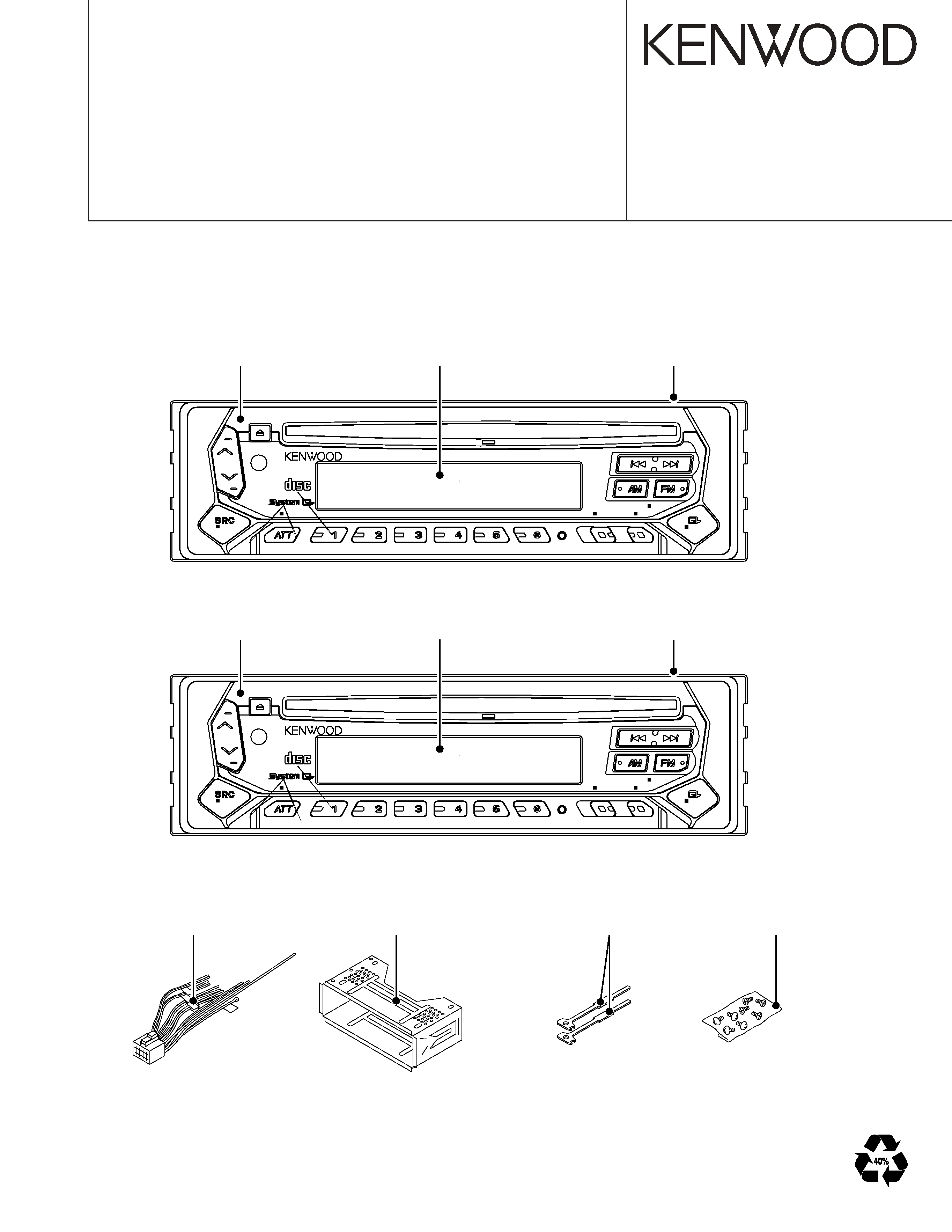
KDC-1022
KDC-122P
SERVICE MANUAL
CD mechanism extension cord : W05-0618-00
COMPACT
RDM
LOUD
REP
SCAN
OFF
KDC-122P
CRSC
AME
AUTO
ADJ
CLK
AUD
45Wx4
Panel assy
(A64-3136-02): KDC-122P
Front glass
(B10-4437-01): KDC-122P
Escutcheon
(B07-3022-02): KDC-122P
COMPACT
RDM
LOUD
REP
SCAN
OFF
KDC-1022
CRSC
AME
AUTO
ADJ
CLK
AUD
50Wx4
Panel assy
(A64-3135-02): KDC-1022
Front glass
(B10-4436-01): KDC-1022
Escutcheon
(B07-3060-02): KDC-1022
DIGITAL AUDIO
DIGITAL AUDIO
DC cord
(E30-4784-05)
Mounting hardware assy
(J21-9716-03)
Lever
(D10-4589-04)x2
Screw set
(N99-1719-05)
KDC-
1022/1
22P
2
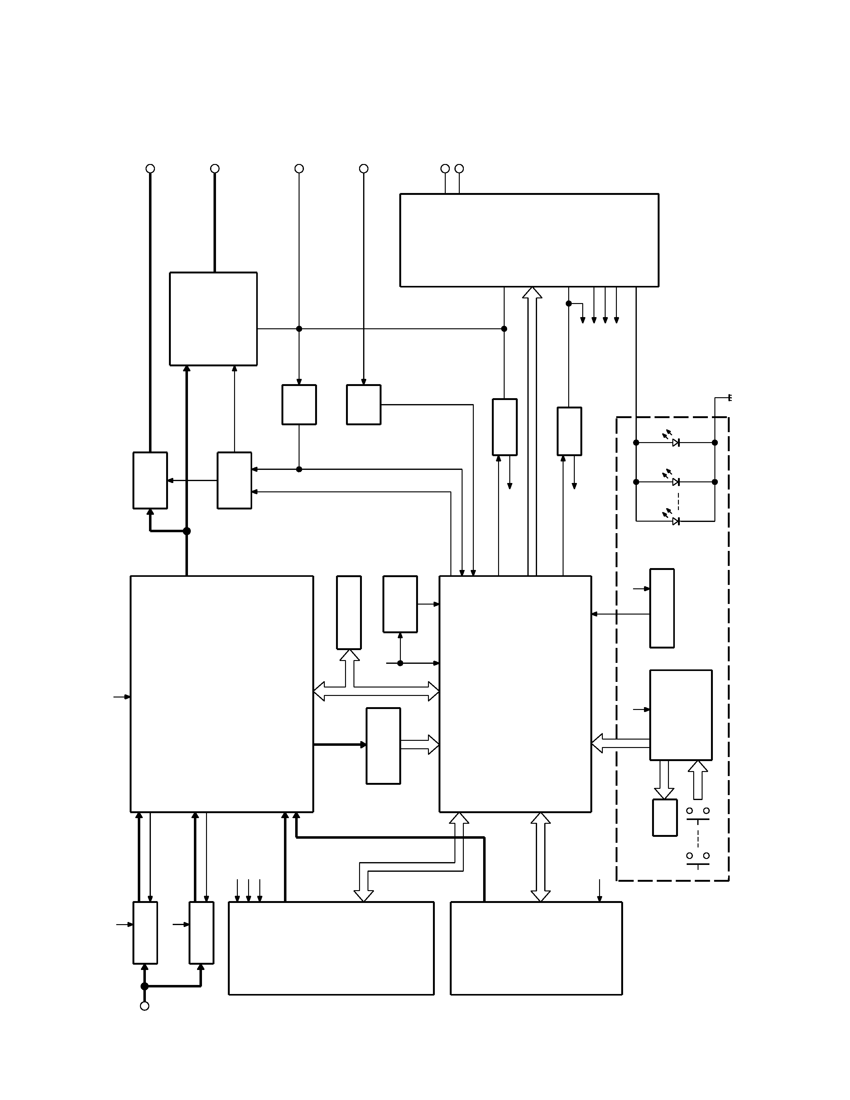
BLOCK
DIA
GRAM
1200mV
1200mV
CD : 3600mV
CH : 3600mV
AM(E) : 855mV
FM(E) : 1372mV
FM(J,K) : 1800mV
AM(J,K) : 600mV
CHANGER
KEY MATRIX
WITH
LCD DRIVER
LCD
REMOCON
MI-COM
CD
ANT
AM AGC
FM AGC
DECODER
RDS
RESET
IC
EEP-ROM
TUNER,MPX &
E-VOL.
SUPPLY IC
SW5V
SERVO
P-ANT
P-CON
POWER
MUTE
LOGIC
DET
ACC
BU
DET
MUTE
PRE
POWER IC
SP
ACC
UP
BACK
OUT
OUT
PRE
IC1
DATA H
MUTE
DATA C
REQ H
CH-CON
AUDIO OUT
CLK
REQ C
RST
BACK UP
BU5V
IC2
SW5V
LO/S
RST
LOE/LIM
MO
LO/EJ
STOP
MUTE
8EJE
SDA
SCLK
AUDIO OUT
12EJE
Q501
Q502
AM+B
FM+B
AM AGC OUT
IC6
CH
CD
SERVO
BU5V
A8V
TUNER
OUT
BU5V
IC11
IC12
IC10
FM AGC OUT
A8V
SW2
SW1
ILLUMI
VCC
BU5V
AUDIO+B
AM+B
FM+B
BA
CK
LIGHT
KEY
ILLUMI
Q51,55
SW5V
Q50
SERVO
BU5V
FM+B
AM+B
A8V
P-CON
P-ANT
IC8
Q20
Q10
IC7
MUTE
Q223,224
IC4
KDC-1022/122P
3
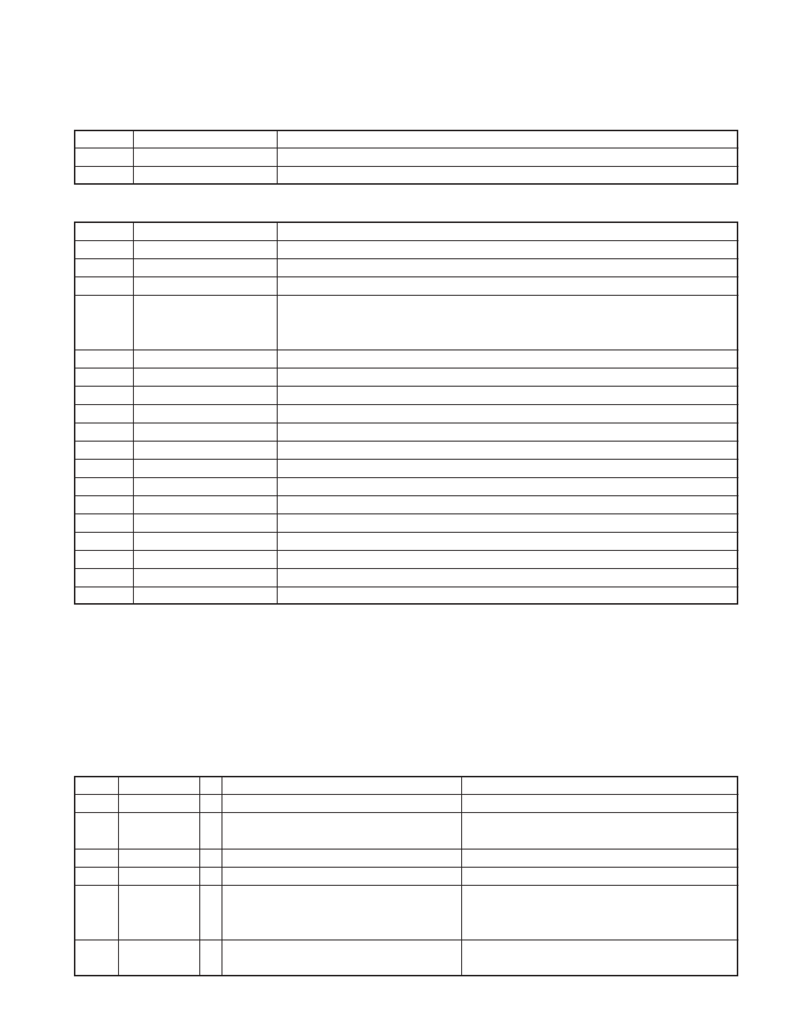
COMPONENTS DESCRIPTION
SWITCH UNIT (X16-2370-12/13)
Ref. No.
Application/Functions
Operation/Condition/Compatibility
IC1
LCD driver & key matrix
Q1
Key scan start
When Q1 base goes Lo, key scan start.
ELECTRIC UNIT (X25-9600-13/14)
Ref. No.
Application/Functions
Operation/Condition/Compatibility
IC1
System control
µ-com
System
µ-com
IC4
Power amplifire
E-Vol output encoder power amplification for speaker.
IC7
Power supply (Multi AVR)
-
When a pin 1, 2, or 13 is "H", MUTE turns on.
IC8
MUTE Logic
When a pin 3, 4, or 5 is "H", P-AMP mute turns on.
Changer is RESET when a pin 9, 10, or 11 is "L".
IC10
Tuner & E-Vol.
FM/AM tuner & stereo decoder & E-Vol.
IC11
Power on reset
When B.U. 5V voltage is less than 3.5V, power reset.
IC12
E2P-ROM
Writing and read-out of adjustment data for a tuner.
Q10
B.U. detector
BU on (base "H") : Collector "H"
Q20
A.C.C detector
ACC on (base : "H") : Collector "L"
Q40
MUTE driver
Base "L" : Mute on (collector "L")
Q50
SW 5V
Base "L" : SW5V on
Q51
SERBO AVR control
Pin 2 "H" : Serbo on (pin 4 "H")
Q55
SERBO AVR
Base "H" : Serbo on
Q70
Surge detector
Base "H" : Surge detect
Q223,224
MUTE
Base "H" : Mute on
Q251
Q501
AM RF amplifire
Base "H" : Gain UP
Q502
FM RF amplifire
Gate "H" : Gain UP
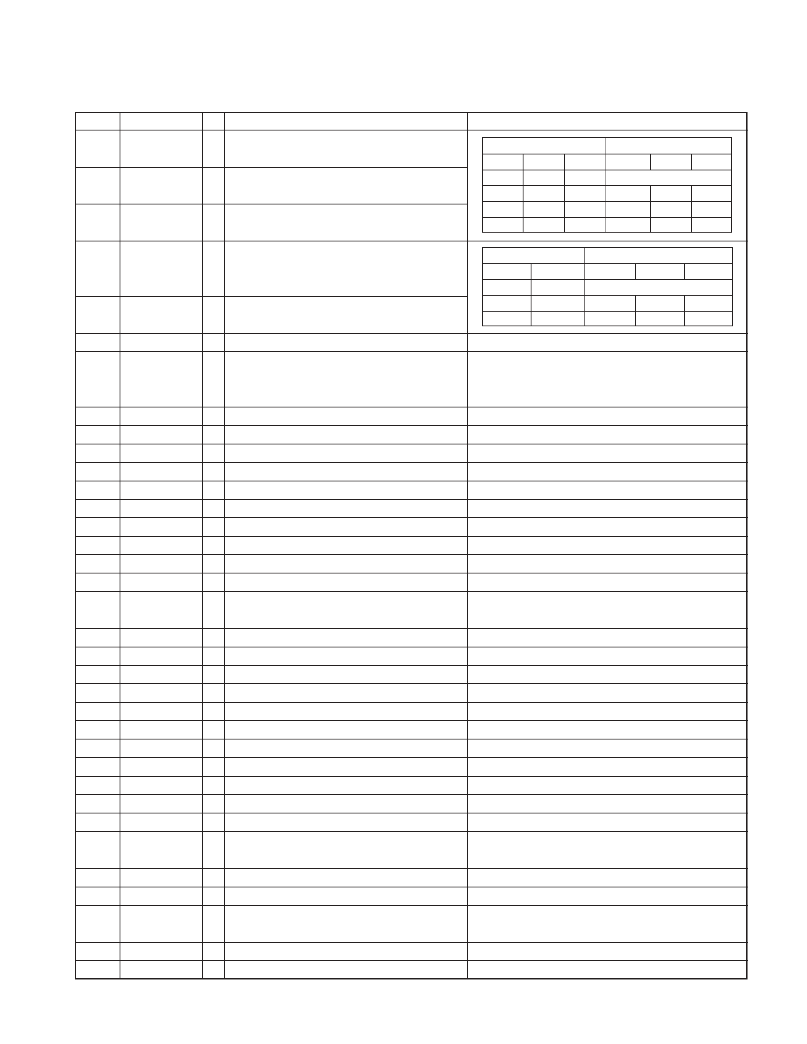
MICROCOMPUTER'S TERMINAL DESCRIPTION
SYSTEM MICROCOMPUTER : UPD780058GC501 (X25 : IC1)
Pin No.
Name
I/O
Description
Processing Operation
1
TDF DET
I
Panel detection
H : Panel detached, L : Panel attached
2
8EJE SW
I
H : Eject is completed
Except 8cm CD model : always output L
3NCO
Not used (out put L)
4Avss
H : Panel detached, L : RESET
5
L-RST
O
LCD driver RESET
3 normal H , Power off L
When 7 seg model, output L
6
L-CE
O
LCD driver selection
H : Select (panel communication)
When panel attached, output L

KDC-1022/122P
4
Pin No.
Name
I/O
Description
Processing Operation
7AVREF1
8NC
Not used (connected to 9pin)
9
IC10-DATA
I/O
IC10, E2PROM data communication
3 non communication : H
10
IC10-CLK
O
IC10, E2PROM clock communication
3 non communication : H
11
L-DATAL
I
Data input from the LCD driver
Non communication : H, When panel detached : L
3 Pull down on X25 unit, Pull up on X16 unit
12
L-DATAS
O
Data output to the LCD driver
When panel detached, output L
13
L-CLK
O
Clock output to the LCD driver
When panel detached, output L
14
R-DATA
I
Data input from the RDS
Except RDS model : output L
15
R-QUAL
I
Quality input from the RDS
Except RDS model : output L
16
CH-DATAC
I
Data input from the changer (new 5L)
Except changer model : output L
17
CH-DATAH
O
Data output to the changer (new 5L)
When non communication, last data keeping
Except changer model : output L
18
CH-CLK
I/O
Clock input/output with the changer (new 5L)
Check the old and new
Except changer model : output L
19
CH-REQH
O
Request output to the changer (new 5L)
L : Requset
Except changer model : output L
20
NC
O
Not used (output L)
21
AFS
O
Noise detection time constant switching terminal
H : Normal, L : FM/AM seek and AF search
3 (When tuner SRC auto zero, L)
22~24
NC
O
Not used (output L)
25
CH-CONT
O
Changer control
H : Changer on, L : Changer off
Except changer model : output L
26
TYPE REF
O
5V lines output for destination setting
H : During destination reading
27
SD
I
Tuner SD input
H : Station detected
28
NC
O
Not used (output L)
29
TYPE2
I
Destination type selection terminal 2
Refer to destination type list.
30
TYPE1
I
Destination type selection terminal 1
Refer to destination type list.
31
TYPE0
I
Destination type selection terminal 0
Refer to destination type list.
32
TUNER-TYPE1
I
Destination available/genuine model rool off
H : genuine model 1, L : available model
33
Vss1
34
TUNER-TYPE0
I
Destination available/genuine model noise cancel
H : genuine model 0, L : available model
35
MUTE
O
Mute (E.Vol, Preset) control
H : mute on, L : mute off
Power off after that 15 second L
36
M-DATA
I/O
Data input/output with the CD mechanism
3 non communication : H
37
M-CLK
O
Clock output to the CD mechanism
3 non communication : H
38
ADJ
O
Tuner lines adjustment
When adjustment = H
PS1-0, 1=L
PS1-2, 2-0, 1=Hi-z
IC10-DATA, CLK=Hi-z
39
P-MUTE
O
Power IC mute control
H : mute off, L : mute on
Power off after that 15 second H
40
SVR
O
Power IC servo control
H : When momentary power down detected, L : Nomal
41
P-STBY
O
Power IC standby control
H : Power IC ON, L : Power IC OFF
42
SW5V
O
SW 5V control
H : SW5V OFF, L : SW5V ON
Power off after that 10 second H
43
B.U-DET
I
Back up detection terminal
H : power down, L : B.U. on
44
ACC-DET
I
ACC detection terminal
H : ACC OFF, L : ACC ON
MICROCOMPUTER'S TERMINAL DESCRIPTION
KDC-1022/122P
5
Pin No.
Name
I/O
Description
Processing Operation
45
PS1-0
O
Power supply IC SW1 control 0
Audio 8V, P-CON
46
PS1-1
O
Power supply IC SW1 control 1
Audio 8V, P-CON
47
PS1-2
O
Power supply IC SW1 control 2
P-ANT
Power supply IC SW2 control 0
48
PS2-0
O
ILL, FM, AM
49
PS2-1
O
Power supply IC SW2 control 1
ILL, FM, AM
50
BEEP
BEEP
H : Light on, L : Light off, When panel attached, output L
51
DSI
O
DSI control
When panel detached, flashing at the panel (H/L)
FIX model is output L
52,53
NC
O
Not used (out put L)
54
LOE/LIM SW
I
CD mechanism down & limit detection
H : Chucking detection, L : Normal
55
MO SW
O
CD mechanism loading motor control output
H : Loading, Eject, Break, L : Play
56
LO/EJ
I/O
CD mechanism loading/Eject switching terminal
H : Eject, L : Loading
57
M-STOP
O
Stop output to the CD mechanism
H : Play, L : Stop
58
M-RST
O
Reset output to the CD mechanism
H : Normal, L : CD mechanism reset
59
M-MUTE
I
Mute input from the CD mechanism
H : mute off, L : mute on
60
RESET
Reset input from the System microcomputer
61
REMO
I
Remote control input
62
R-CLK
I
RDS clock input
Except RDS model : output L
63
CH-REQC
I
Request input from the changer (new 5L)
H : Changer detection, L : Request
Except Changer model : output L
64
LOS SW
I
CD mechanism loading's switch detected
H : No disc, L : DISK IN (Loading Start)
65
KEY-REQ
I
Key input detected (11pin L connected to the DATA L)
H : Key no input, L : Key input (edge key data reading start)
66
12EJE SW
I
12cm disc detected
L : 12cm disc
67
Vss0
68
VDD1
69
X2
3 MAIN X'tal oscillating circuit
3 4.19MHz X'tal connection
70
X1
3 MAIN X'tal oscillating circuit
3 4.19MHz X'tal connection
71
IC
TEST
72
XT2
Not used
OPEN
73
XT1
74
VDD0
VDD
Connected to VDD
75
AVREF0
A/D converter reference voltage control output,
connection to the 80pin AVCONT
76
S-METER
I
S-meter input
77
NOISE
I
FM noise detection input
3
78
PHONE
I
2way mute
2.5V or greater : NAVI MUTE, 1.0V or less : TEL MUTE
Except phone mute model : output L
79
NC
O
Not used (output L)
80
AVCONT
O
A/D converter standard voltage control output
H : During A/D converter active, Same timing with PON
MICROCOMPUTER'S TERMINAL DESCRIPTION
BA4911 SW1
Power supply IC output
PS1-2
PS1-1
PS1-0
A8V
P-CON P-ANT
LLL
STANDBY
LL (H)
H (L)
ON
OFF
OFF
LH
H
ON
ON
OFF
HH
H
ON
ONON
BA4911 SW2
Power supply IC output
PS2-1
PS2-0
ILLUMI
FM
AM
LL
STANDBY
L (H)
H (L)
ON
ON
OFF
HH
ON
OFF
ON