© 1999-12 PRINTED IN JAPAN
B51-7574-00 (N) 1793
CD RECEIVER
SERVICE MANUAL
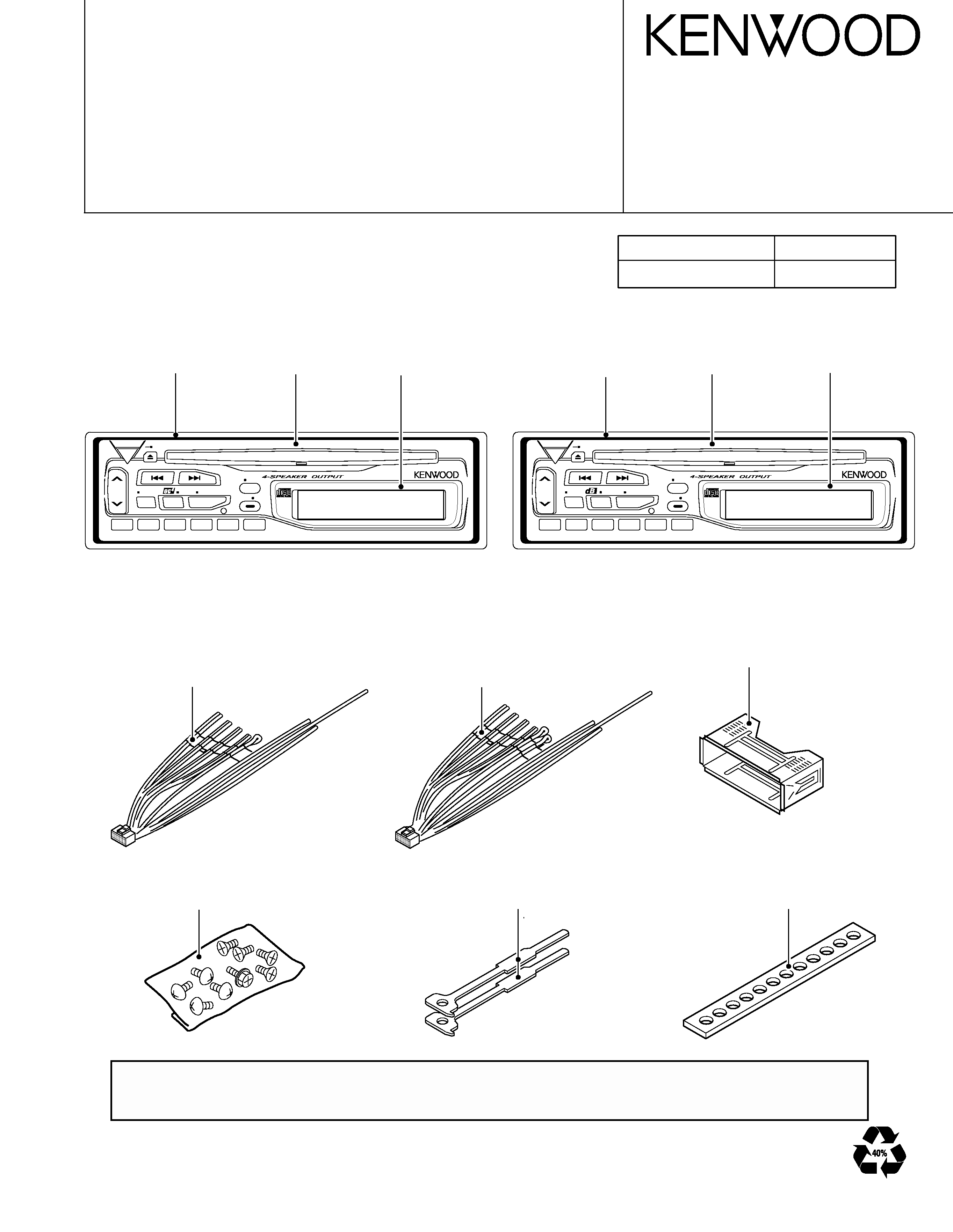
KDC-1016/115S
1
23
45
6
SRC
BAND
CLK
ATT
AUD
PWR OFF
AME
ADJ
AUTO
SCAN
RDM
REP
KDC-115S
LOUD
A.ADJ
CRSC
HIGH POWER 45Wx4
1
23
45
6
SRC
BAND
CLK
ATT
AUD
ADJ
CRSC
PWR OFF
AME
AUTO
SCAN
RDM
REP
KDC-1016
LOUD
HIGH POWER 45Wx4
A.ADJ
The MECHANISM OPERATION DESCRIPTION is the same as model KDC-S3007 and KDC-5050RG.
Please refer to the service manual for model KDC-S3007(B51-7029-00) or KDC-5050RG(B51-7099-00).
DC cord
(E30-4783-05)
:KDC-115S
(E30-4784-05)
:KDC-1016
DC cord
Lever
(D10-3031-04)x2
Illustration is KDC-115S.
Mounting hardware assy
(J21-9491-03)
Screw set
(N99-1632-05)
Escutcheon
(B07-2181-02)
Front glass
(B10-3146-03)
Panel assy
(A64-1938-02)
Escutcheon
(B07-2181-02)
Front glass
(B10-3146-03)
Panel assy
(A64-1939-02)
Extension cord
Parts No.
CD mechanism(22P)
W05-0618-00
Stay
(J54-0606-04)
Illustration is KDC-1016.

KDC-1016/115S
2
BLOCK DIAGRAM ........................................................................................ 3
COMPONENT DESCRIPTION ...................................................................... 4
MICRO COMPUTER'S DECRIPTION ........................................................... 6
ADJUSTMENT ............................................................................................. 8
PC BOARD .................................................................................................... 9
SCHEMATIC DIAGRAM ............................................................................. 15
EXPLODED VIEW ....................................................................................... 21
PARTS LIST ................................................................................................ 23
SPECIFICATIONS .................................................................... BACK COVER
CONTENTS
KDC-1016/115S
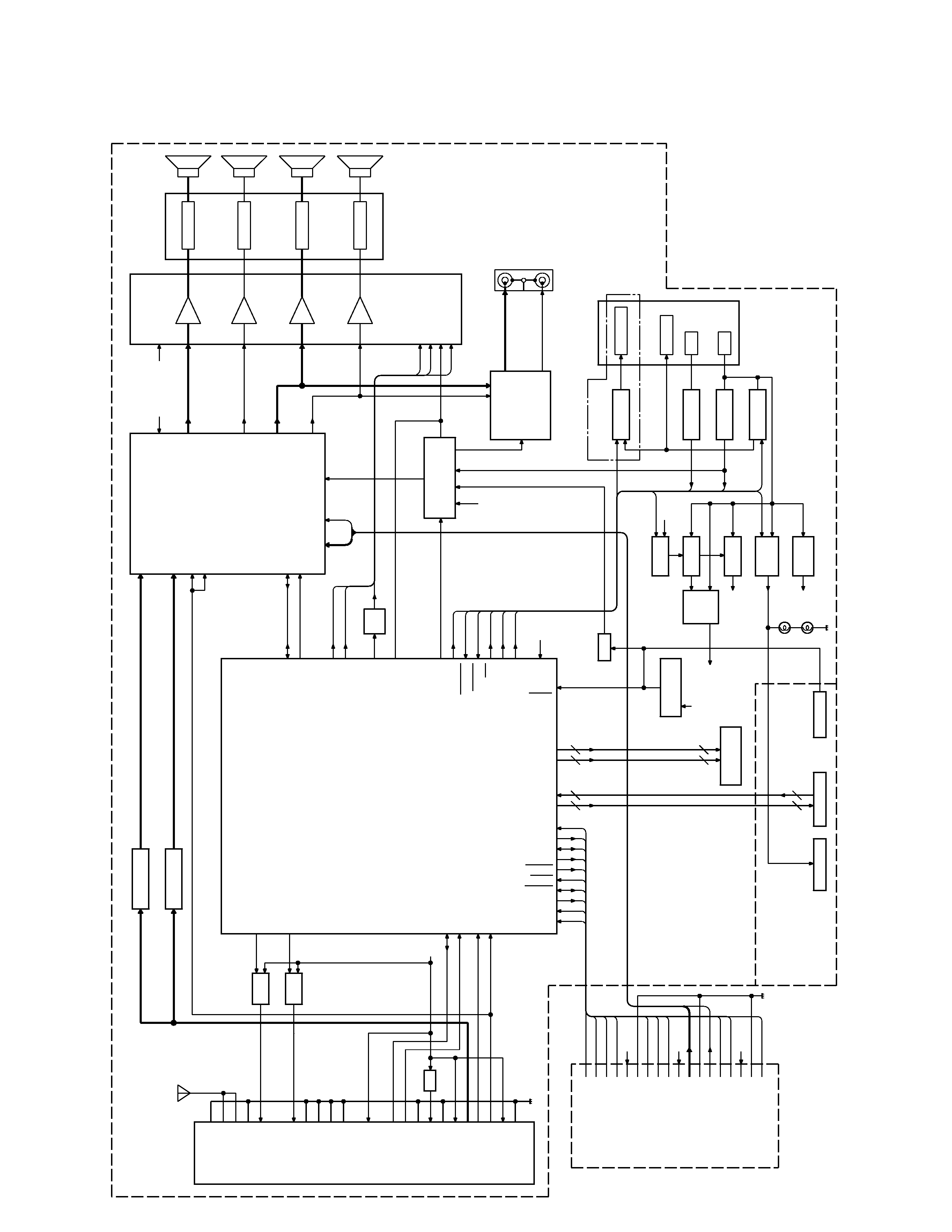
BLOCK DIAGRAM
IC1
A1
(X13)
KEY
MUTE
B.U
DET
B.U
ACC
P-CONT
MUTE
PRE
POWER
IC
N.C./MPX
E-VOL.
FRONT
Lch
FRONT
Rch
REAR
Lch
REAR
Rch
J1
LED
CD
MECHA
1
Lch
2
Rch
PRE
OUT
IC2
IC4
IC6
SP
OUT
REAR
RST
SW
RST
IC
KDC-1016
IC5
ACC
DET
P-CONT
ANT
-CONT
J1
J2
FM+B
AM+B
5V
AM
BPF
FM
BPF
SW5V
8V
ILLUMI
BU5V
SYSTEM
u-COM
RST
ANT
-CONT
7SEG
LCD
ED1
SW14V
SER
VO
Q30,31
Q32,33
Q23,24
SW
SVR
Q25
Q40
Q15
Q3,4
Q6,7
Q9-12
Q1,2
Q8
Q14
Q13
Q18-21
Q16,17
Q28,29
FM
ANT
AM
ANT
RF
GND
FM+B
AM+B
OSC
GND
OSC
GND
OSC
GND
N.C.
(VT)
PLL
+B
AM
IFOUT
SDA
SCL
DIG
GND
IF1+B
IF1
GND
S-METER
IF2
GND
SD
FM+B
SW5
ACC
DET
B.U
DET
SCK
MUTE
SDA
P
CON
RESET
SW3
MOSW
MP
IN
AM
MPX
OUT
RR
OUT
LR
OUT
RF
LEVEL
SCK
SDA
OUT
LF
STBY
P
.MUTE
B.U
SMUTE
9
BU5V
AM+B
VDD
5V
LO/EJ
ANT
CON
BEEP
SVR
AMP
.STBY
SVR
AC
GND(BEEP)
Rch
Lch
CD
:3529mV
AM
:546mV
FM
:1781mV
RF
GND
OSC
GND
IF2
+B
AUDIO
OUT
8V
S-METER
SD
PLL-CLK
PLL-DA
T
A
BU5V
B.U.5V
8V
BU5V
AM:
170mV
FM:
400mV
MST
OP
ILL
9
KS0-KS4
KI0-KI3
25
25
SEG1-SEG22
COM1-COM3
P
.MUTE
8V
BU5V
SER
VO
MRST
MMUTE
MDA
TA
MCLK
SW1
SW2
SW2
SW1
M
CLK
M
DA
T
A
BU
5V
D
GND
M
MUTE
M
RST
M
ST
OP
AUDIO+B
Lch
GND
Rch
LO/EJ
MO
SW
SER
VO+B
SER
VO
GND
SW3
BU
5V
8V
SER
VO
1200mV
3
KDC-1016/115S
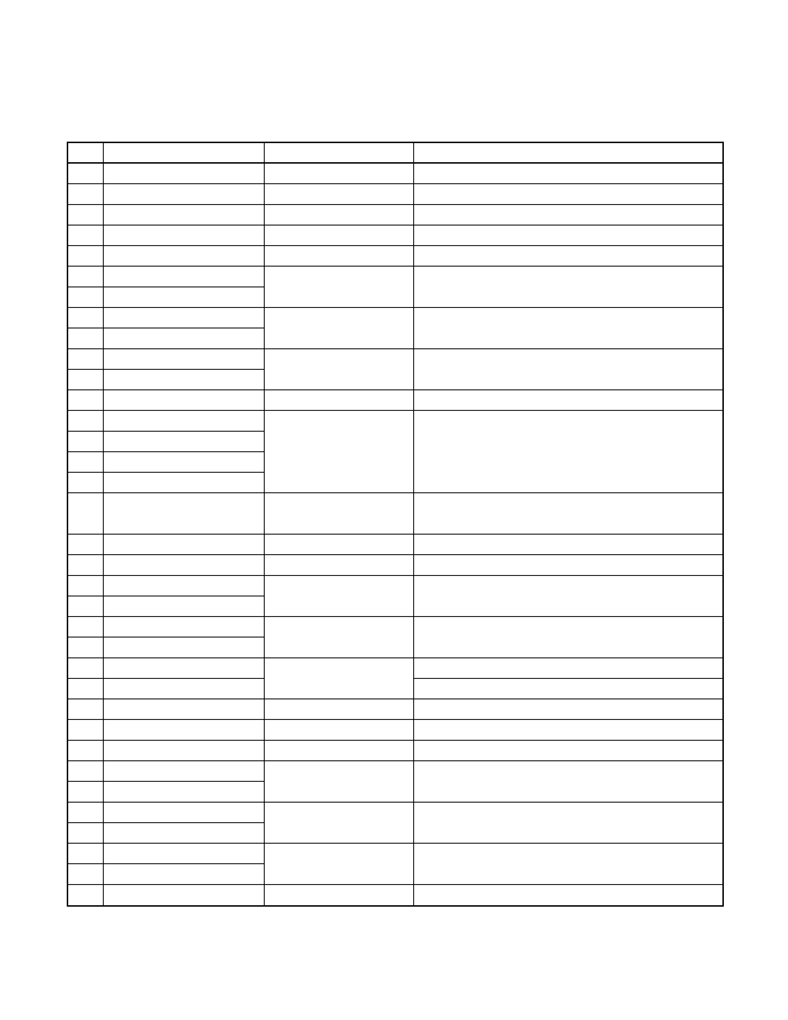
COMPONENT DESCRIPTION
4
ELECTRIC UNIT(X25-8420-XX)
Ref.No.
Component Name
Application/Function
Operation/Condition/Compatibility
IC1
M38258MCD067FP
System MI-COM.
IC2
TDA7400D
E-VOL. & N.C. MPX
IC4
TDA7386
Power IC
IC5
PST9135NR
Reset IC
"Lo": Detection voltage below 3.5V
IC6
HD74HC27FP
Mute logic
3 input NOR gate x3
Q1
2SB1565(E,F)or2SB1655(E,F)
BU 5V AVR
Inverted darlington connection
Q2
2SC2412Kor2SD601A
ON during BU applied.
Q3
DTA124EKorUN2112orKRA103S
SW14V
Audio 8V AVR and Servo AVR ON/OFF control
Q4
DTC144EKorUN2213orKRC104S
Q3 is turned ON when Q4's base goes "Hi".
Q6
2SB1184
Audio 8V AVR
Inverted darlington connection
Q7
2SC2412Kor2SD601A
Q6 is turned ON when Q7's base goes "Hi".
Q8
2SD2396
Servo AVR
ON when the base goes "Hi".
Q9
DTC144EKorUN2213orKRC104S
Illumination AVR
Inverted darlington connection
Q10
DTA124EKorUN2112orKRA103S
ON when Q9's base goes "Hi".
Q11
2SB1184
Q12
2SC2412Kor2SD601A
Q13
2SC2412Kor2SD601A
BU detection(Momentary
ON when the base goes "Hi" during BU applied.
power down detection)
Q14
2SC2412Kor2SD601A
ACC detection
ON when the base goes "Hi" during ACC applied.
Q15
2SA1036K
SW 5V
ON when the base goes "Lo".
Q16
2SB1277(Q,R)
P-ANT SW
Q16 is turned ON when Q17's base goes "Hi".
Q17
DTC114YKorUN2214
ON during FM/AM reception
Q18
2SB1277(Q,R)
P-CON SW
Q18 is turned ON when Q21's base goes "Hi".
Q21
DTC114YKorUN2214
ON while power is on or CD loading/eject.
Q19
2SB709A
P-CON protection
Protect Q18 by turning ON when P-CON output is grounded.
Q20
DTA124EKorUN2112orKRA103S
Prevents Q19 tuning ON during start-up after power ON.
Q23
DTA124EKorUN2112orKRA103S
Mute driver for Audio mute SW
ON when the base goes "Lo".
Q24
DTC144EKorUN2213orKRC104S
E-VOL. mute SW
E-VOL. is muted when the base goes "Hi".
Q25
DTC114YKorUN2214
SVR SW
POWER IC RESET is activated when the base goes "Hi".
Q28
DTC143TKorUN2216
Audio mute SW
Audio pre-outs are muted when the base goes "Hi".
Q29
DTC143TKorUN2216
Q30
2SB1277(Q,R)
FM+B SW
Q30 is turned ON when Q31's base goes "Hi" .
Q31
DTC124EKorUN2212
ON during FM reception
Q32
2SB1277(Q,R)
AM+B SW
Q32 is turned ON when Q33's base goes "Hi" .
Q33
DTC124EKorUN2212
ON during AM reception
Q40
DTA144EKorUN2113
RESET SW
Audio mute is activated when the panel reset SW is pushed.
KDC-1016/115S
5
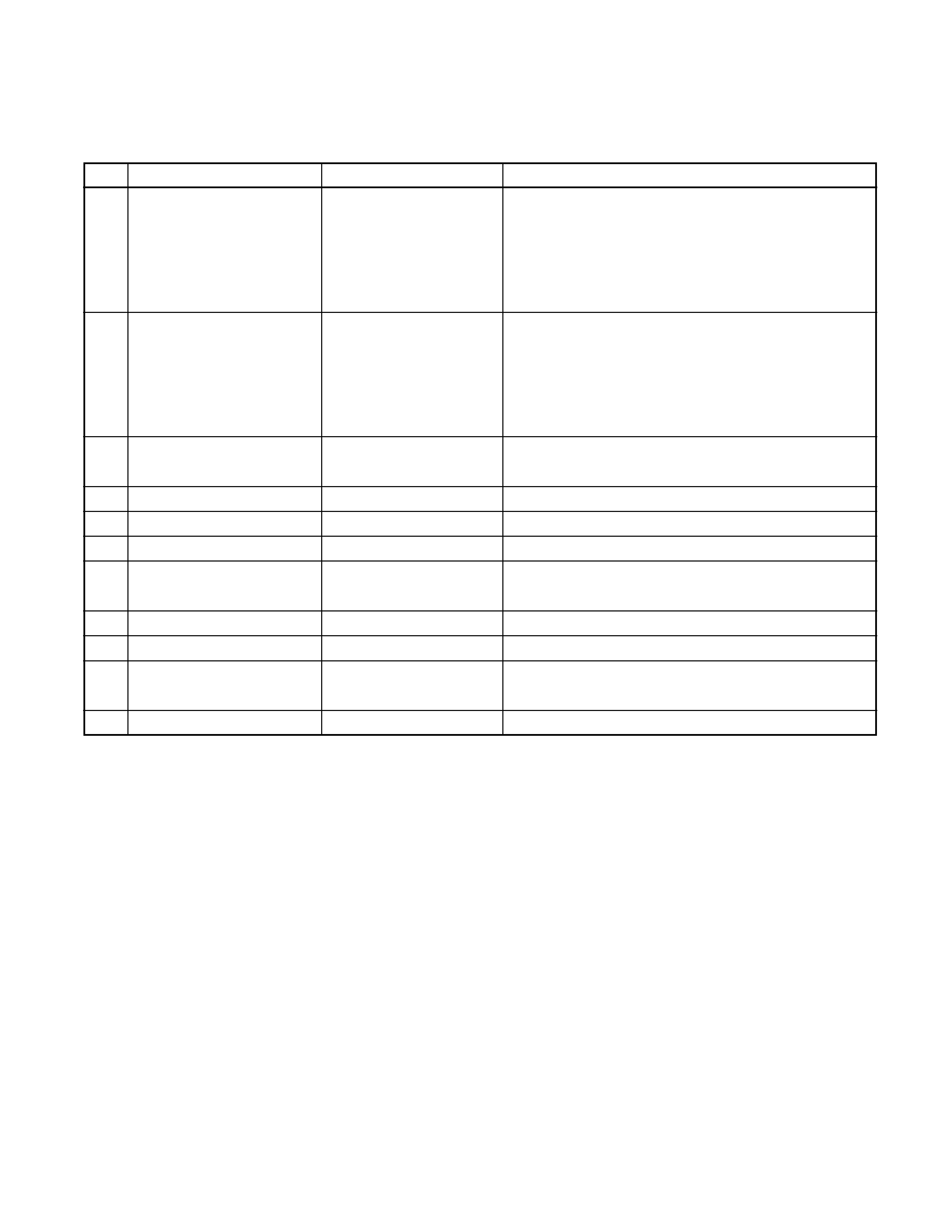
COMPONENT DESCRIPTION
CD PLAYER UNIT(X32-4700-00)
Ref.No.
Component Name
Application/Function
Operation/Condition/Compatibility
IC1
AN8806SB
RF amplifier
Generation of RF signal based on the signals from the
APC circuit and pickup, and generation of servo
error(focusing error and tracking error) signals. Detection
of dropout, anti-shock, track crossing and off-track
conditions.
IC2
MN662774KC3
CD signal processor bult-in MI-COM.
Focusing, tracking, sled and spindle servo processing.
Automatic adjustment(focusing, tracking, gain, offset
and balance) operations. Digital signal
processing(DSP, PLL, sub-codes, CIRC error correction,
audio data interpolaration) operations.
IC4
BA5917AFP
BTL driver
Focusing coil, tracking coil, spindle motor and sled
motor driver
IC5
TA78L05F
5V AVR
IC6
NJM4565MD
Active filter
Low pass filter
Q1
2SB1188
APC
LD power control
Q2
DTC124EUA
P ON SW
Q3 and Q4 are turned ON when Q2's base goes "Hi"
during the source selected CD.
Q3
2SA1362(Y)
A.8V SW
A8V line ON/OFF control ON, when the base goes "Lo".
Q4
2SA1362(Y)
D.5V SW
D5V line ON/OFF control ON, when the base goes "Lo".
Q5
DTC124EUA
MOTOR SW
Q4 is turned ON when Q5's base goes "Hi" during CD
loading or eject.
Q8
DTC124EUA
GAIN CONTROL SW