© 2000-2 PRINTED IN JAPAN
B51-8573-00(S) 1433
KCT-31
INTERFACE CABLE
SERVICE MANUAL
OUTLINE ................................................................... 2
FEATURES ................................................................ 2
TERMINAL FUNCTION ............................................. 2
INSTALLATION ......................................................... 2
PARTS LIST ............................................................... 3
SCHEMATIC DIAGRAM ............................................ 3
PC BOARD VIEWS .................................................... 4
CONTENTS
2
KCT-31
OUTLINE/FEATURES/TERMINAL FUNCTION/INSTALLATION
OUTLINE
1. The KCT-31 is a RS-232C interface cable for LMR Mobile
radios, TK-780,880,980,981 and TK-785,885.
The 9-pin (D-sub) connector is connected to an external
RS-232C terminal.
The other end of the cable is connected to the internal
connector of LMR mobile radio.
Note: You cannot write a firmware with the KCT-31.
FEATURES
1. This KCT-31 has a RS-232C-TTL level interface circuit.
2. This KCT-31 does not require an external power supply.
3. This KCT-31 can be used up to 9600 bps.
4. Compatible with an ER terminal of DTE that has the voltage
6V or more.
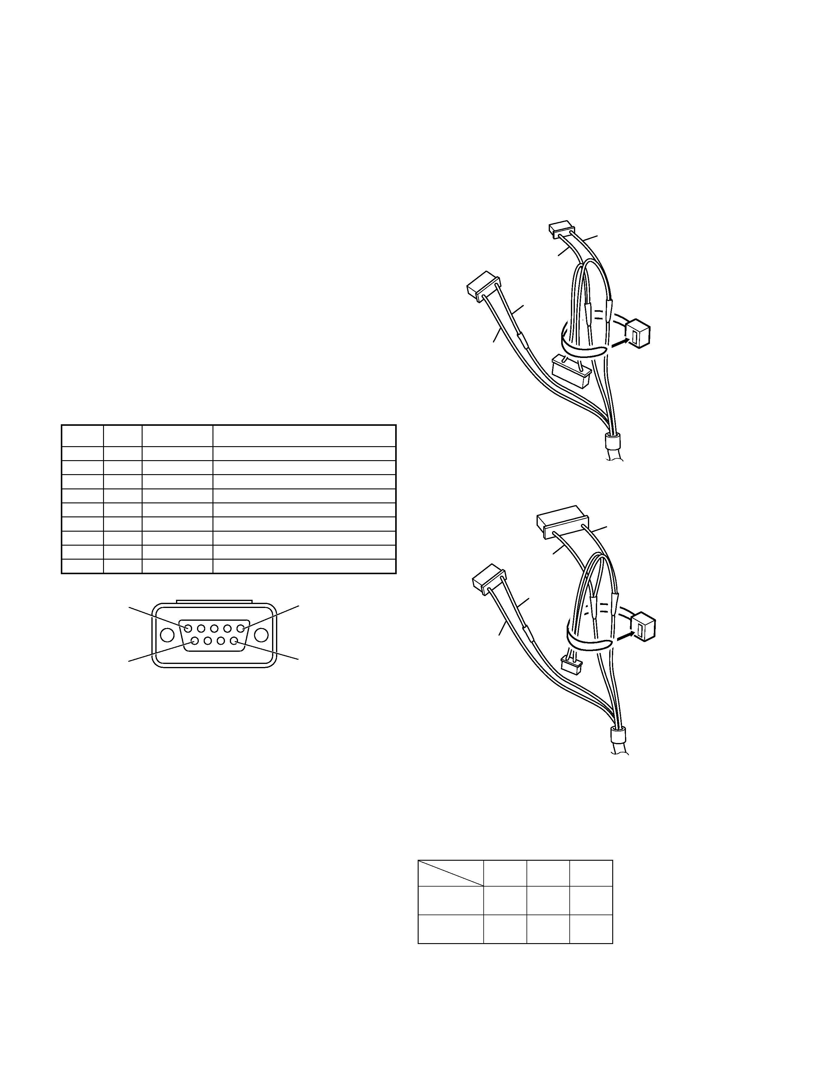
D-SUB Connector
Pin No. I/O
Port Name
Function
1
I
CD
Carrier detect
2
I
RD
Receive data
3
O
SD
Transmit data
4
O
ER
Data terminal ready
5
-
SG
Signal ground
6
I
DR
Data set ready
7
O
RS
Request to send
8
l
CS
Clear to send
9
-
CI
Ring indicator
Red
Black
Yellow
Green
A
B
C
9
5
1
6
Fig. 1
INSTALLATION
Note: When the COM 1 is used, A connector is unused.
When the COM 2 is used, C connector is unused.
1. Bind the unused connector to the cable with a retaining
band as shown.
Red
Black
Yellow
Green
A
B
C
When the COM 1 is used.
When the COM 2 is used.
AB
C
1
M
O
CO
NS
E
YS
E
Y
2
M
O
CS
E
YS
E
YO
N
connector
TERMINAL FUNCTION
2. Make sure the unit's power is tuned off.
3
KCT-31
INSTALLATION/PARTS LIST/SCHEMATIC DIAGRAM
Note:
Enable the Serial Port function on the terminal.
Refer to the service manual of each radio or the help file that
came with the FPU (Field Programming Unit) for details.
1
2
A
B
3
4
6
5
CN6
CN1
CN2
CN4
CN3
A
B
7
C
Fig. 2
Fig. 3
PARTS LIST
New Parts.
indicates safety critical components.
Parts without Parts No. are not supplied.
Les articles non mentionnes dans le Parts No. ne sont pas fournis.
Teile ohne Parts No. werden nicht geliefert.
Destination
KCT-31
Ref. No.
Parts No.
Description
Address
New
parts
KCT-31
!
C1
C92-0601-05
ELECTRO
10UF 16WV
C2
C92-0712-05
CHIP-TAN 22UF 6.3WV
D1
DAP202U
DIODE
D2
MA2S111
DIODE
IC1
NJM78L05UA
BI-POLAR IC
IC2
TC4S81F
MOS IC
Q1
2SC4116(Y)
TRANSISTOR
Q2
DTC114YUA
TRANSISTOR
Q3
DTA144EUA
TRANSISTOR
Q4
DTC114EUA
TRANSISTOR
R1
RK73GB1J223J
CHIP R
22K
J
1/16W
R2
RK73GB1J392J
CHIP R
3.9K
J
1/16W
R3
RK73GB1J103J
CHIP R
10K
J
1/16W
R4
RK73GB1J473J
CHIP R
47K
J
1/16W
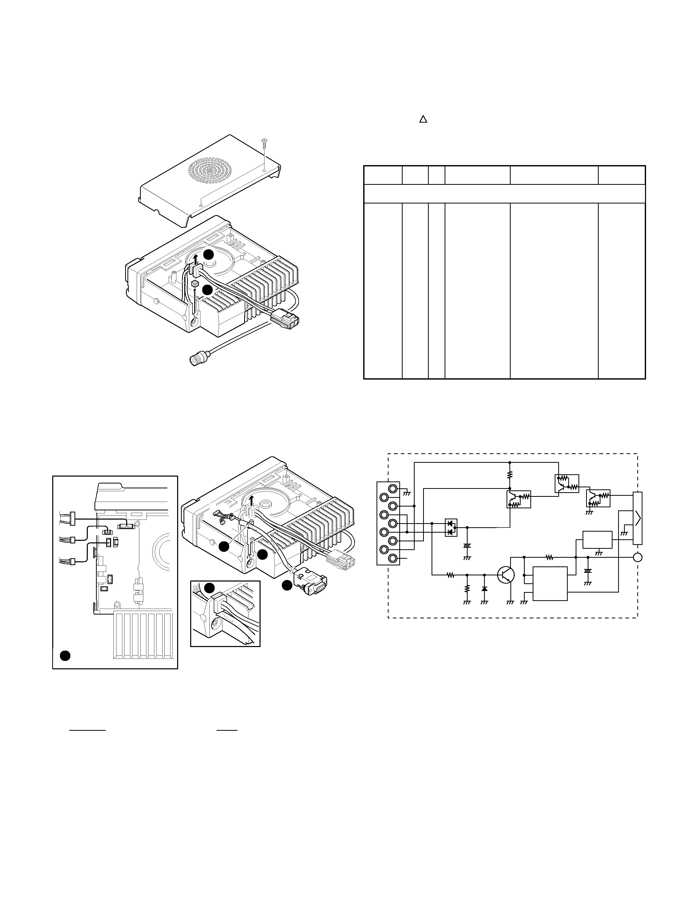
3. Remove the upper case of the transceiver and lift the DC
cable bushing () from the chassis.
4. Remove the pad as shown in figure2 ().
5. Insert the KCT-31 cable () into the chassis ().
The wire retaining band () must be inside the chassis.
6. Replace the DC cable bushing ().
7. Connect the KCT-31 to the TX-RX unit (A/2) as shown in
figure 3 ().
8. Replace the upper case.
SG
CD
DR
RD
RS
SD
CS
ER
C I
95
61
IC1
NJM78L05UA
OUT
IN
COM
1
2
3
3
2
1
TXD
CN1
RXD
SB
5V
VDD
OUT
IC2
TC4S81F
MA2S111
VSS
INA
INB
R4
47k
15
2
34
GND
4
Q1
2SC4116(Y)
10
µ
16
C1 +
D1
DAP202U
Q2
DTC114YUA
R2
3.9k
Q3
DTA144EUA
Q4
DTC114EUA
22
µ
6.3
C2
R1
22k
R3
D2
10k
SCHEMATIC DIAGRAM
Note:
The above modification has already been applied to the TK-
780/TK-880 transceivers with a serial number of 30200001 or
greater.
When using a COM2 port, replace the 47 k
(R675) chip
resistor on the TX-RX unit B/2 with a 4.7 k
resistor.
Original
New
47k
(RK73GB1J473J)
= 4.7k (RK73GB1J472J)
4
KCT-31
KENWOOD CORPORATION
14-6, Dogenzaka 1-chome, Shibuya-ku, Tokyo 150-8501, Japan
KENWOOD SERVICE CORPORATION
P.O. BOX 22745, 2201 East Dominguez Street, Long Beach, CA 90801-5745,
U.S.A.
KENWOOD ELECTRONICS CANADA INC.
6070 Kestrel Road, Mississauga, Ontario, Canada L5T 1S8
KENWOOD ELECTRONICS DEUTSCHLAND GMBH
Rembrücker Str. 15, 63150 Heusenstamm, Germany
KENWOOD ELECTRONICS BELGIUM N.V.
Mechelsesteenweg 418 B-1930 Zaventem, Belgium
KENWOOD ELECTRONICS FRANCE S.A.
13, Boulevard Ney, 75018 Paris, France
KENWOOD ELECTRONICS U.K. LIMITED
KENWOOD House, Dwight Road, Watford, Herts., WD1 8EB United Kingdom
KENWOOD ELECTRONICS EUROPE B.V.
Amsterdamseweg 37, 1422 AC Uithoorn, The Netherlands
KENWOOD ELECTRONICS ITALIA S.p.A.
Via G. Sirtori, 7/9 20129 Milano, Italy
KENWOOD IBERICA S.A.
Bolivia, 239-08020 Barcelona, Spain
KENWOOD ELECTRONICS AUSTRALIA PTY. LTD.
(A.C.N. 001 499 074)
16 Giffnock Avenue, Centrecourt Estate, North Ryde, N.S.W. 2113, Australia
KENWOOD ELECTRONICS (HONG KONG) LTD.
Unit 3712-3724, Level 37, Tower one Metroplaza, 223 Hing Fong Road, Kwai Fong, N.T.,
Hong Kong
KENWOOD ELECTRONICS TECHNOLOGIES(S) PTE LTD.
Sales Marketing Division
1 Ang Mo Kio Street 63, Singapore 569110
6
Pin
7
Pin
8
Pin
9
Pin
Q1
D2
R3
R4
C1
IC2
IC1
5
Pin
R1
C2
D1
Q2
R2
Q3
Q4
4
Pin
3
Pin
2
Pin
CN1
1
Pin
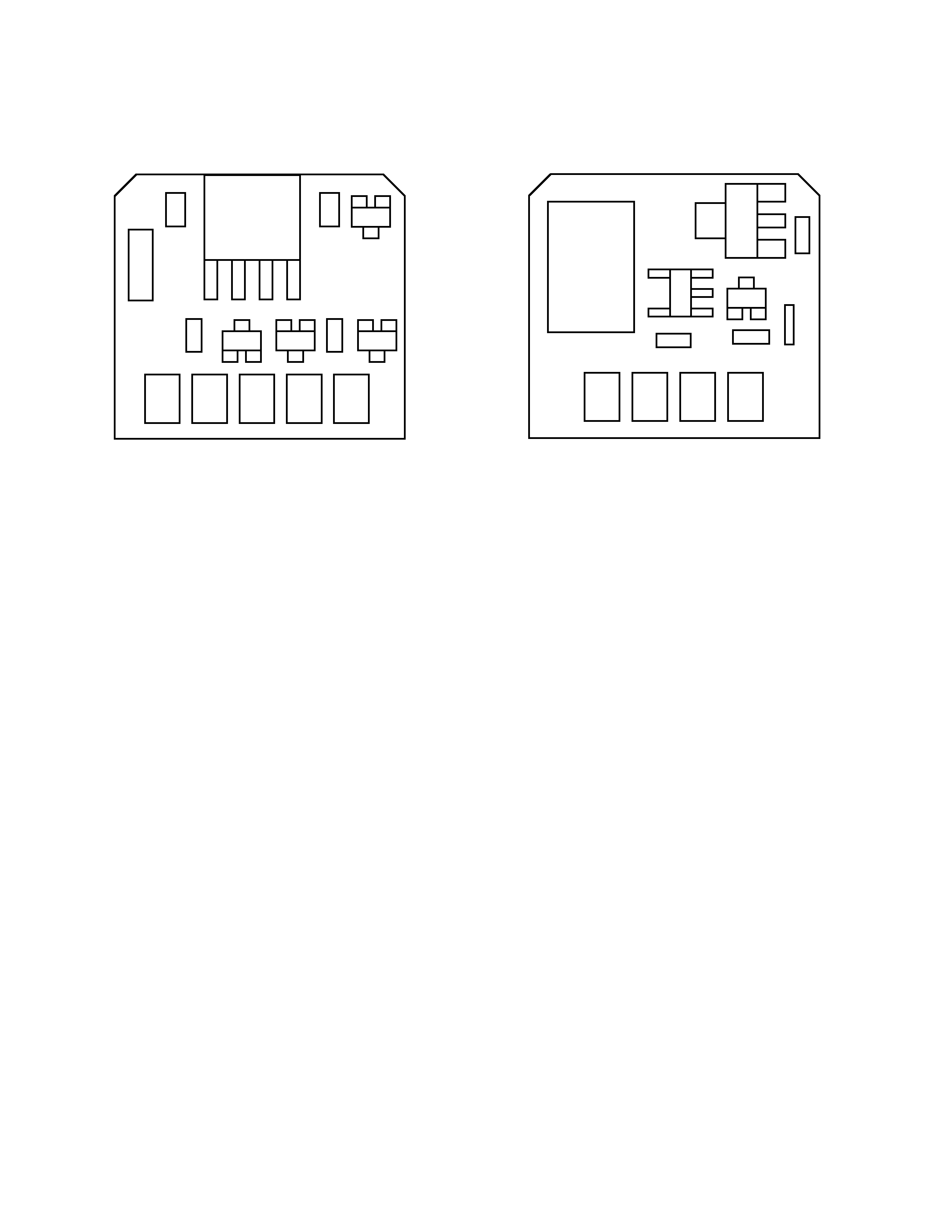
Component Side View
Foil Side View
PC BOARD VIEWS