PHONES
A
SPEAKER
B
BASS
TREBLE
BALANCE
INPUT SELECTOR
MUTING
LOUDNESS
ON
OFF
POWER
ON/STANDBY
MIN
MAX
VOLUME CONTROL
MD
TAPE
TUNER
PHONO
CD
SOURCE DIRECT
thermally reactive advanced instantaneous transistor
T R A I T
L
R
SL 16 XS-8
+
+
PHONO
CD
TUNER
TAPE
SYSTEM CONTROL
SPEAKERS
AC OUTLETS
UNSWITCHED
100W MAX.
SWITCHED TOTAL
200W MAX.
AC 100V 50/60Hz
A or B : 416
, A and B : 816
REC
PLAY
REC
PLAY
MD
SIGNAL GND
L
R
L
R
L
R
B
A
AC 220
AC 230--
240V
AC 110--
120V
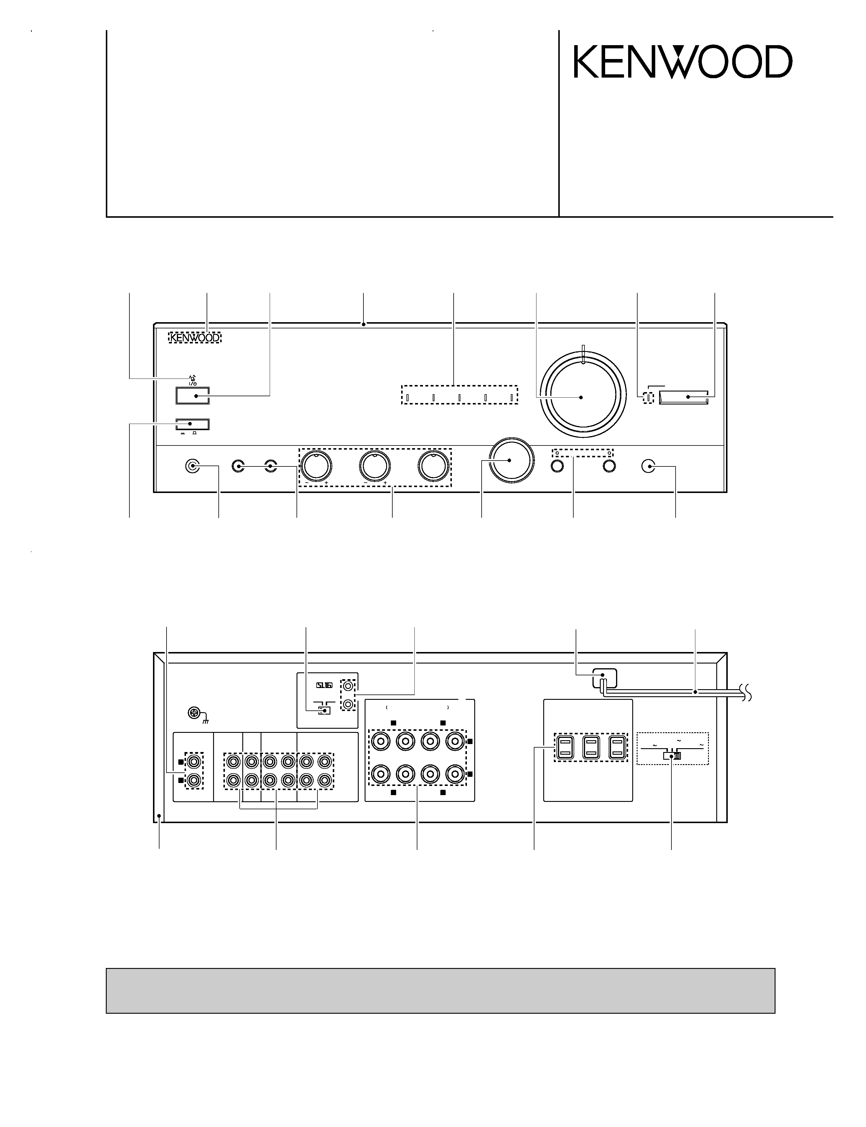
STEREO INTEGRATED AMPLIFIER
KAF-1010/3010R
SERVICE MANUAL
© 1998-3/B51-5415-00 (K/K) 1948
Power lens
(B19-1596-08)
Badge
(B43-0302-04)
Power knob*
(K29-)
Speaker knob
(K29-7376-08)
Control knob
(K29-7383-08)
Selector knob
(K29-7379-08)
Push SW
(S68-0105-08)
Phone jack (D6.5)
(E11-0263-08)
Phono jack (2P)
(E11-0188-05)
Slide switch*
(S62-)
Matellic cabinet
(A01-3630-08)
AC power cord bushing
(J42-0200-08)
AC power cord*
(E30-)
Screw terminal board
(E70-0104-08)
AC outlet*
(E03-)
Slide switch
(S62-0069-08)
System jack (D3.5)
(E11-0333-08)
Phono jack (4P)x3
(E63-0186-08)
Front panel
(A60-1492-08)
Function lens
(B19-1592-08)
Volume knob
(K29-7381-08)
Direct lens
(B19-1593-08)
Front frame*
(A22-)
Illustration is KAF-3010R.
* Refer to parts list on page 18.
Loudness lens
(B19-1594-08)
Caution : No connection of ground line if disassemble the unit.
Please connect the ground line on rear panel, PCBs, Chassis and some others.
Remocon window
(B11-0371-08)
KAF-1010(K)1P 98.4.253:57PM y[W 2
KAF-1010/3010R
2
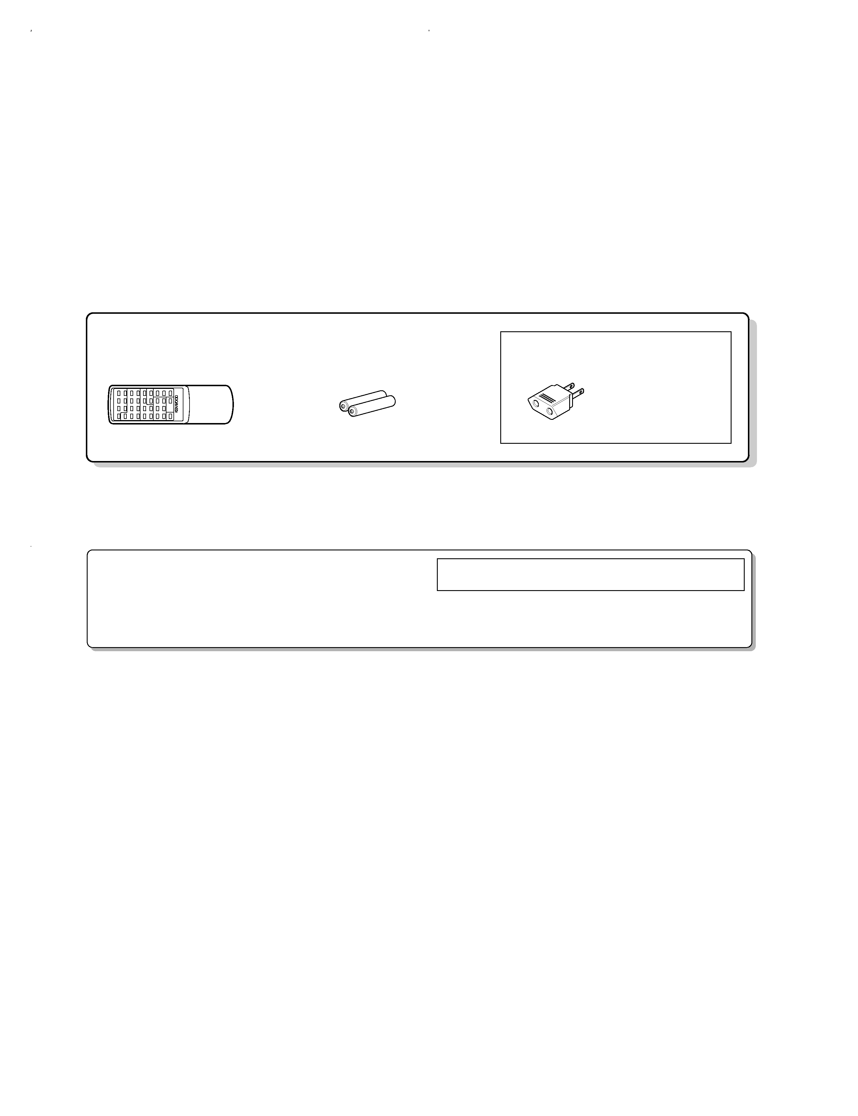
CONTENTS / ACCESSORIES
Contents
Accessories
Caution
CONTENTS / ACCESSORIES ....................................2
CONTROLS .................................................................3
CIRCUIT DESCRIPTION .............................................5
ADJUSTMENT ............................................................ 6
PC BOARD ..................................................................7
SCHEMATIC DIAGRAM ............................................11
EXPLODED VIEW .....................................................17
PARTS LIST...............................................................18
SPECIFICATIONS .....................................................21
Remote control unit (1)
(KAF-3010R only)
Batteries (R6/SUM-3)
(E03-0115-05)
(A07-1232-08)
(2)
(KAF-3010R only)
AC plug adaptor (1)
Use to adapt the plug on
the power cord to the
shape of the wall outlet.
(Accessory only for
regions where use is
necessary.)
Operation to reset
The microcomputer may fall into malfunction (impossibility to
operate, erroneous display, etc.) when the power cord is un-
plugged while power is ON or due to an external factor. In this
case, execute the following procedure to reset the microcom-
puter and return it to normal condition.
Set the
POWER to OFF then, while holding down the REMOTE
POWER key, set the MAIN POWER key to ON.
·Please note that resetting the microcomputer clears the contents
stored in it and returns it to the condition when it left the factory.
KAF-1010(K)1P 98.4.253:57PM y[W 3
KAF-1010/3010R
3
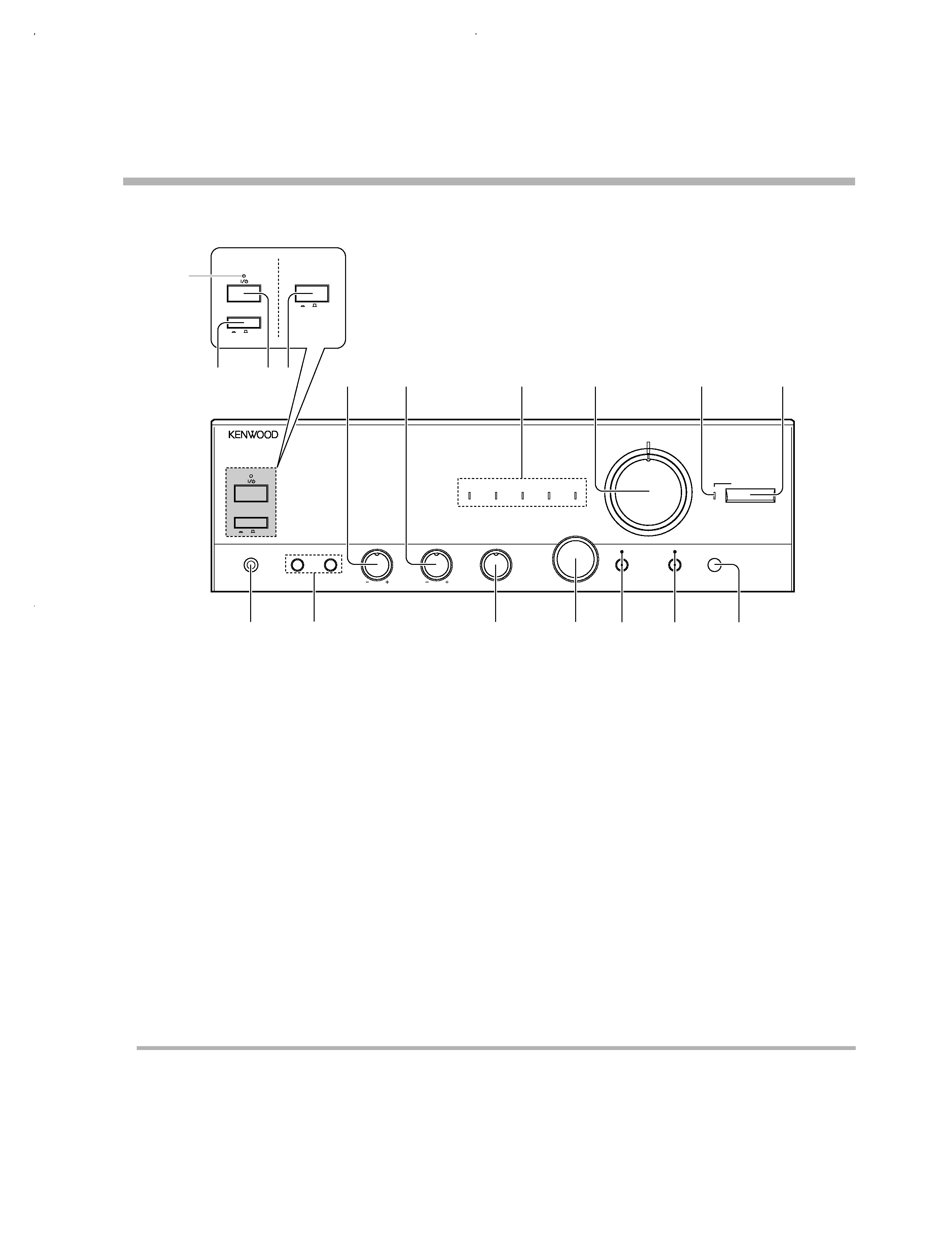
CONTROLS
Main unit
About the standby indicator (KAF-3010R only)
This unit has a standby indicator that lights to show that a small amount of current is being supplied to the unit in order to preserve the
memory. This is called the Standby mode. When the Standby indicator is lit, the amplifier can be switched
ON / STANDBY from the remote
control.
1 POWER switch (KAF-3010R)
Usually leave this switch to the on position.
When the unit is not to be used for a long period of time, set
the switch to the
OFF position for safety.
2 ON/STANDBY key (KAF-3010R)
This key effective when the
POWER key is set
to the on (standby) position, and pressing this key
turns power
ON and off (standby).
3 Standby indicator (KAF-3010R)
4 POWER switch (KAF-1010)
5 BASS knob
To adjust low frequencies.
6 TREBLE knob
To adjust high frequencies.
7 INPUT indicator
An indicator lights for the source selected
with the
INPUT SELECTOR knob.
8 VOLUME CONTROL knob
Adjust the volume.
9 SOURCE DIRECT indicator
Usually leave this switch to the on (standby) position.
0 SOURCE DIRECT key
To listen to a source with high quality sound.
! PHONES jack
Used for headphone listening.
@ SPEAKERS A/B switches
Press to select the A and/or B speaker systems.
# BALANCE knob
Adjust the volume balance between left and right.
$ INPUT SELECTOR knob
Turn to select the input sources.
% MUTING key/indicator
Mute the sound temporarily.
^ LOUDNESS key/indicator
Use to emphasize deep bass sounds.
& Remote sensor(KAF-3010 ONLY)
5
5
PHONES
A
SPEAKER
B
BASS
TREBLE
BALANCE
INPUT SELECTOR
MUTING
LOUDNESS
ON
OFF
POWER
ON/STANDBY
MIN
MAX
VOLUME CONTROL
MD
TAPE
TUNER
PHONO
CD
SOURCE DIRECT
thermally reactive advanced instantaneous transistor
T R A I T
L
R
3
1
4
2
5
6
7
8
9
0
&
^
%
$
#
@
!
ON
OFF
ON
OFF
POWER
POWER
ON/STANDBY
KAF-3010R
KAF-1010
KAF-1010(K)1P 98.4.253:57PM y[W 6
KAF-1010/3010R
4
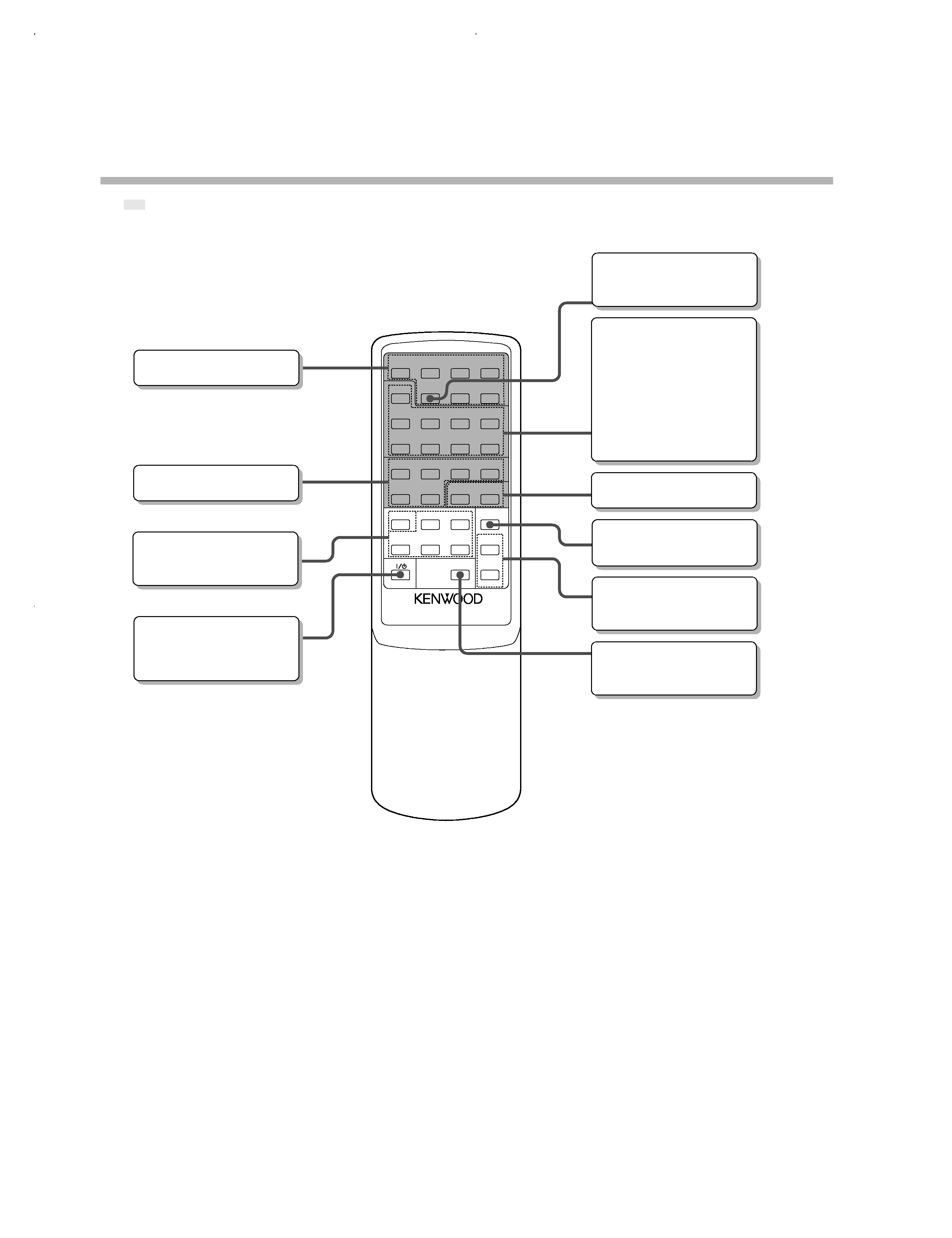
CONTROLS
REMOTE CONTROL UNIT
MODEL: RC-A0300
4
¢
7
6
4
¢
7
3
8
1
¡
8
fi
fi
%
%
1
¡
2
7
3
A
DISC SKIP
B
AUX
TUNER
CD
TAPE
POWER
MD
PHONO
MUTE
VOLUME
CONTROL
SOURCE
DIRECT
TUNER
P.CALL
CD
TAPE
MD
The
part of the illustration designates keys that can be used to operate KENWOOD components connected with the system
control. The rest of the illustration designates keys that have the same functions as the keys on the main unit.
Model: RC-A0300
Infrared ray system
Remote control unit (KAF-3010R only)
DISC SKIP key
Only used for the Autochanger
CD player.
INPUT SELECTOR keys
AUX key does not function with
this unit.
POWER key
Use to switch the power
ON/
STANDBY when the POWER
switch is turned ON.
TUNER operation keys
MUTING key
Mute the sound temporarily.
VOLUME UP(
%), DOWN(fi)
keys
Adjust the volume.
SOURCE DIRECT key
To listen to a source with high
quality sound.
TAPE operation keys
These keys perform the same
operations as the correspond-
ing keys on the cassettes
deck.
However, operations requir-
ing simultaneous press-ing of
two keys are not possible.
CD player operation keys
MD recorder operation keys
KAF-1010(K)1P 98.4.253:57PM y[W 7

5
CIRCUIT DESCRIPTION
KAF-1010/3010R
Pin No.
Pin Name
I/O
Description
1
DATA
O
Output of DATA signal for control of input selector.
2
CLOCK
O
Output of CLOCK signal for control of input selector.
3
ST
O
Output of STROBE signal for control of input selector.
4
NC
- No use.
5
8/16
O
8bit/16bit selector.
6
1010/3010R
O
Model selector.
7
PROTECT
I
Protection detector.
8
REMOCON
I
Remote control signal input.
9
STANDBY
O
Standby led control signal output.
10
PHONO
O
Phono led control signal output.
11
CD
O
CD led control signal output.
12
TUNER
O
Tuner led control signal output.
13
TAPE1
O
Tape1 led control signal output.
14
MD
O
MD led control signal output.
15
LOUDNESS
O
Loudness led control signal output.
16
MUTE
O
Mute led control signal output.
17
GND
- Gnd.
18
RESET
I
Reset signal input.
19,20
XIN,OUT
I/O Crystal connecting port for clock generation.
21
VSS
- Gnd.
22
VAREF
- Analog reference voltage input.
23
KEY
I
A/D key input.
24
POW RE
O
Power relay control signal output.
25
VOL UP
O
Motor volume control.
26
VOL DOWN
O
Motor volume control.
27
MUTE
O
Selector mute control.
28
SP
O
Speaker relay control.
29
LOUDNESS
O
Loudness control.
30,31
EN
I
Rotary encoder signal for input selector.
32
S BUSY
I/O System serial BUSY signal interface.
33
S DATA
I/O System serial DATA signal interface.
34
R MUTE
O
Rec mute circuit control signal output.
35,36
NC
- No use.
37
VOL LED
O
Volume led control.
38
S DIRECT
O
S.DIRECT led control signal output.
39
POW OFF
I
Power off signal input.
40,41
NC
- No use.
42
VDD
- Power supply(+5V).
Microprocessor : TMP87C846N (IC501)
KAF-1010(K)1P 98.4.253:57PM y[W 10