
KAC-PS500F
4-CHANNEL POWER AMPLIFIER
7 Page 2-13
INSTRUCTION MANUAL
AMPLIFICATEUR DE PUISSANCE 4 CANAUX
7 Page 14-25
MODE D'EMPLOI
4-KANAL-ENDSTUFE
7 Page 26-37
BEDIENUNGSANLEITUNG
4-KANAALS-EINDVERSTERKER
7 Page 38-49
GEBRUIKSAANWIJZING
AMPLIFICATORE DI POTENZA A 4 CANALI
7 Page 50-61
ISTRUZIONI PER L'USO
AMPLIFICADOR DE POTENCIA DE 4 CANALES
7 Page 62-73
MANUAL DE INSTRUCCIONES
AMPLIFICADOR DE POTÊNCIA DE 4 CANAIS
7 Page 74-85
MANUAL DE INSTRUÇÕES
© B64-1215-00 (EM)
LA DICHIARAZIONE DI CONFORMITA' "CE"
DI QUESTO PRODOTTO E' DEPOSITATA
PRESSO:
KENWOOD ELECTRONICS EUROPE B.V.
AMSTERDAMSEWEG 37
1422 AC UITHOORN
THE NETHERLANDS
English
3
Installation procedure
Since there are large variety of settings and connections possible according to applications, read
the instruction manual well to select the proper setting and connection.
1. Remove the ignition key and disconnect the negative - terminal of the battery to prevent
short circuits.
2. Set the unit according to the intended usage.
3. Connect the input and output cables of the units.
4. Connect the speaker cables and sigma servo feed back cables.
5. Connect the power cable, power control cable and grounding cable following this order.
6. Install the unit in the car.
7. Connect the negative - terminal of the battery.
· If sound is not output normally, immediately turn power off and check connections.
· Be sure to turn the power off before changing the setting of any switch.
· If the fuse blows, check cables for shorts, then replace the fuse with one of the same rating.
· Check that no unconnected cables or connectors are touching the car body. Do not remove
caps from unconnected cables or connectors to prevent short circuits.
· Connect the speaker cables to appropriate speaker connectors separately. Sharing the
negative cable of the speaker or grounding speaker cables to the metal body of the car can
cause this unit to fail.
· After installation, check that the brake lamps, winkers, and wipers work properly.
2CAUTION
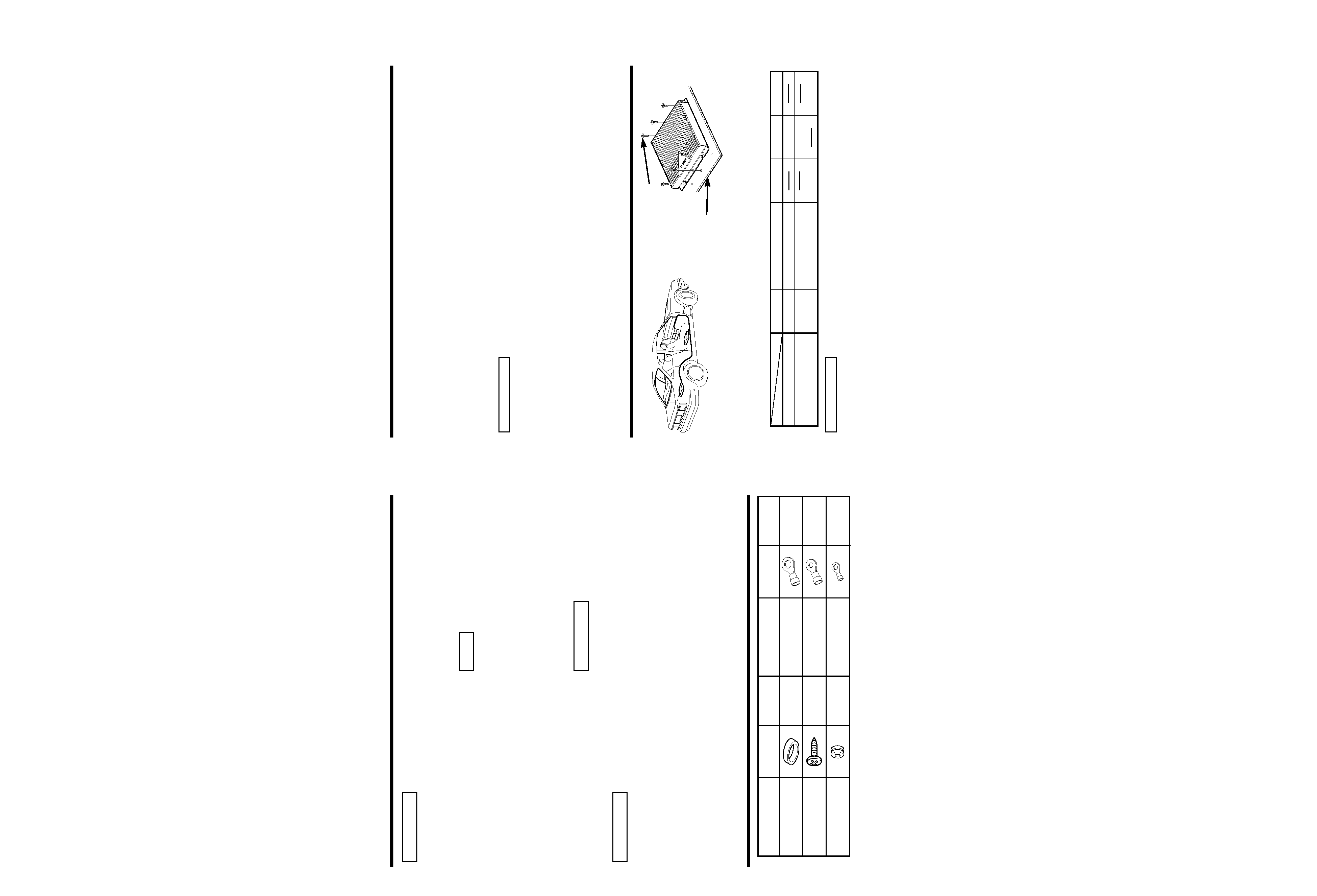
Installation
· Since the power amplifier has no parts which require operation, it can be installed at a position
away from the driver's seat without any hindrances.
As generally accepted positions for its installation, places such as inside the trunk, etc. can be
considered.
· Use the extension cables. (Optional.)
· Do not install the unit under the carpet. Otherwise heat build-up occurs and the unit may be
damaged.
· Install this unit in a location which allows heat to easily dissipate.
Once installed, do not place any object on top of the unit.
· This unit has cooling fans to decrease the internal temperature. Be careful not to block the
cooling fan openings when installing the unit. Blocking these openings will inhibit the cooling
of the internal temperature and result in malfunction.
· After installing the unit, check to make sure that electrical equipment such as the brake lamps,
turn signal lamps and windshield wipers operate normally.
· Install the unit securely in a location that does not interfere with driving.
2CAUTION
Installation board, etc.
(thickness : 15 mm or more)
Self-tapping screw
(ø5
× 18 mm)
CA-2SL
CA-12SL
CA-22SL
CA-52SL
RCA cable
CA-3WL
CA-13WL
CA-23WL
CA-53WL
RCA cable (ø7mm)
CA-5W
CA-15W
CA-25W
CA-45W
CA-65W
RCA cable (ø12mm)
0.5m
1m
2m
4m
5m
6m
Type
Length
2 English
Safety precautions
Take the following precautions to
prevent fire and avoid personal
injury :
· When extending the battery cable, or
ground cable, use 5mm2 (AWG10) or
larger automotive grade cable to avoid
cable deterioration or damage to the
covering.
· Check that no metal objects (coins, tools,
etc.) are left inside the unit to avoid short
circuits.
· If you smell or see smoke, turn the
power off immediately and consult your
Kenwood dealer.
· Do not touch the unit during use because
the surface of the unit becomes hot and
may cause burns if touched.
Take the following precautions to
keep the unit in proper working
order.
· Be sure the unit is connected to a 12V
DC power supply with a negative ground
connection.
· Do not open the top or bottom cover.
· Do not install the unit in places it is
exposed to direct sunlight, high heat or
humidity, water may splash over it, or
dust exists.
· If you have difficulty in installing this unit
in your vehicle, contact your Kenwood
dealer.
Cleaning the unit
· If the surface is dirty, wipe it clean with a
silicon cloth or soft dry cloth with the
power off.
Do not use hard cloths or paint thinner,
alcohol, or other volatile solvents. These
may damage external surfaces or remove
indicator characters.
2CAUTION
NOTE
2CAUTION
2WARNING
Accessories
Part name
Number
of Items
External
View
Terminal cover
(Power terminal)
1
Self-tapping screws
(ø5
× 18 mm)
6
Grommets
1
Part name
Number
of Items
External
View
Round terminal
(Large)
1
Round terminal
(Medium)
2
Round terminal
(Small)
1
4 English
English
5
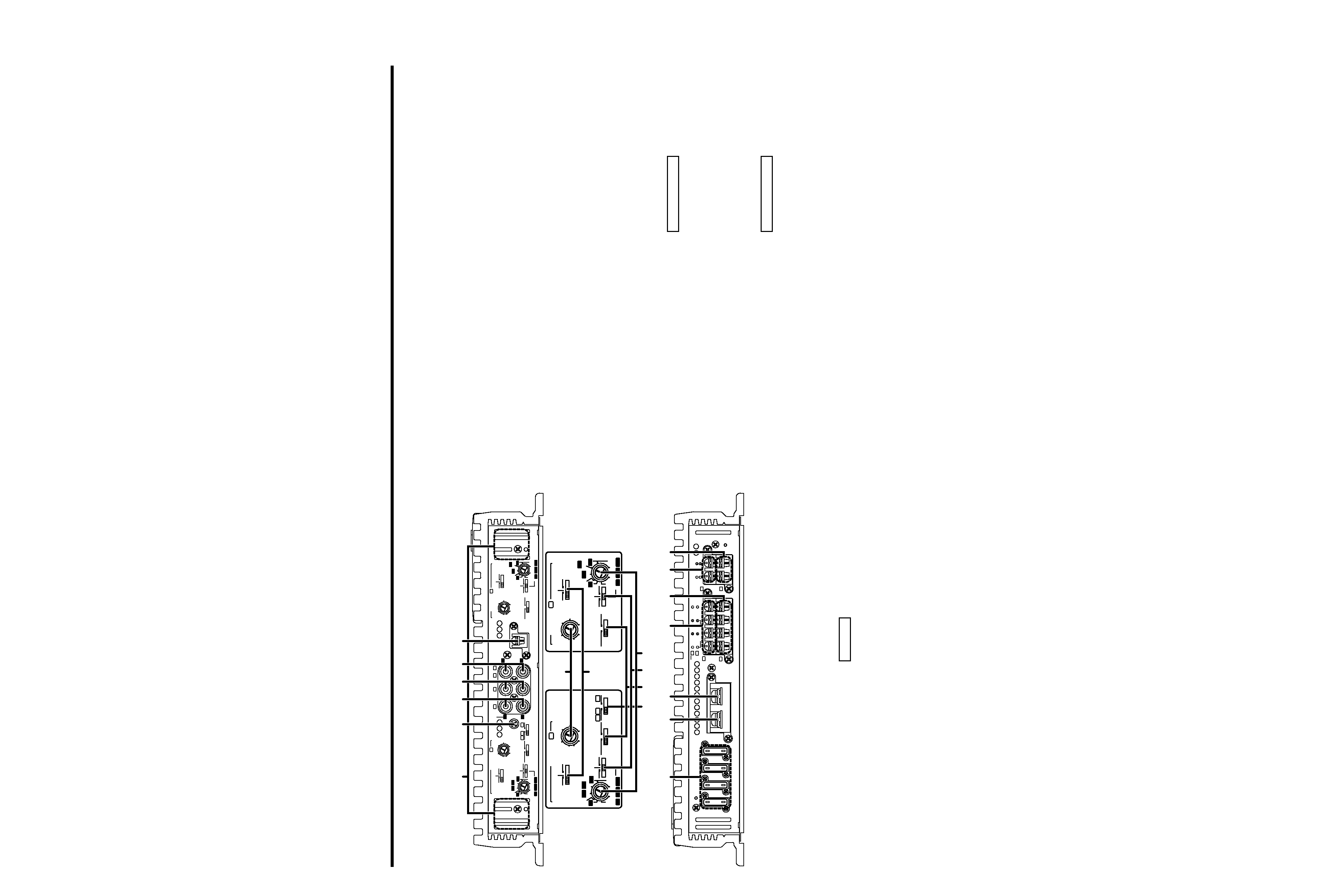
Controls
This is a 4 channel amplifier including 2 stereo amplifiers in a body. One amplifier is
referred to as amplifier A and the other is amplifier B. This unit is compatible with
a large variety of systems by combining the switches and functions described in
the following.
L
L
R
R
LINE IN
P.CON(REMOTE)
GND
MONO
LINE OUT
25Hz
15Hz
INFRASONIC
FILTER
OFF
OPERATION
MONO
STEREO
OPERATION
MONO
STEREO
25Hz
15Hz
INFRASONIC
OFF
LPF
OFF
HPF
FILTER
LPF
OFF
HPF
CONTROL
INPUT
SENSITIVITY(V)
0.2
5
0.5
1
2
FREQUENCY(Hz)
FREQUENCY(Hz)
50
70
100
LPF 200
170
120
50
70
200
150
120
100
HPF
150
3
4
INPUT
SELECTOR
LEFT
BRIDGED
SERVO
FEED BACK
RIGHT
SPEAKER OUTPUT
FUSE(20A
×4)
BATT.
GND
B
B
B
A
A
B
B
B
A
A
A
A
A
A
+
(MAX)
(MIN)
INPUT
SENSITIVITY(V)
0.2
5
0.5
1
2
3
4
(MAX)
(MIN)
CONTROL B
50
70
100
LPF 200
170
120
50
70
200
150
120
100
HPF
150
2
0
2
0
2
0
2
0
25Hz
15Hz
INFRASONIC
FILTER
OFF
OPERATION
MONO
STEREO
LPF
OFF
HPF
CONTROL
INPUT
SENSITIVITY(V)
0.2
5
0.5
1
2
50
70
100
LPF 200
170
120
50
70
200
150
120
100
HPF
150
3
4
INPUT
SELECTOR
B
A
A
A
(MAX)
(MIN)
OPERATION
MONO
STEREO
25Hz
15Hz
INFRASONIC
OFF
FILTER
LPF
OFF
HPF
INPUT
SENSITIVITY(V)
0.2
5
0.5
1
2
3
4
(MAX)
(MIN)
CONTROL B
50
70
100
LPF 200
170
120
50
70
200
150
120
100
HPF
150
1
2
3 4 5 6
7
#
$ %
^
&
* (
8
9 0 ! @
Amplifier A
Amplifier B
1
Cooling fans
When the internal temperature of the
amplifier rises, the cooling fans are
activated automatically to drop the
temperature. In certain situations, the
cooling fans may be operating from the
beginning of the amplifier operation.
2
RCA cable ground lead terminal
3
Amplifier A LINE IN terminal
4
Amplifier B LINE IN terminal
5
LINE OUT terminal
These jacks output respectively the signals
input to amplifiers A and B. They always
output the stereo signals regardless of the
position of the OPERATION switch.
6
Power control (REMOTE) terminal
7
INPUT SENSITIVITY control
Adjust this control according to the pre-out
level of the center unit connected to this
amp.
The sensitivities of amplifiers A and B can
be adjusted independently regardless of
the position of the input selector switch.
Refer to "Specifications" on the center
unit's instruction manual about the pre-out
level.
8
INFRASONIC FILTER FREQUENCY
switch
When this switch is set to 15 Hz or 25 Hz,
frequencies below the setting value will be
cut. This serves to get rid of unwanted
NOTE
vibrations that do not result in sound and
improves the speakers' ability to reproduce
sound. Note that the speaker output will
automatically be set for monaural (L+R)
sound.
9
INPUT SELECTOR switch
This switch selects the input method of the
signals to be amplified by amplifiers A and
B.
· A B position:
Amplifies both of the signals input to
amplifiers A and B.
· A position:
Amplifies only signal input amplifier A with
both amplifiers A and B.
0
OPERATION switch
The amplification methods of the signals
input to amplifiers A and B can be selected
independently according to the setting of
this switch.
· STEREO position:
The amplifier can be used as a stereo
amplifier.
· MONO (Lch) position:
Amplifies the signal input from the left side
only. Set to this position and make bridged
connections to use as a high-power
monaural amplifier. (The input right signal is
not output.)
!
FILTER switch
This switch allows to apply high-pass or
low-pass filtering to the speaker outputs.
· HPF (High-Pass Filter) position:
The filter outputs the band of higher
frequencies than the frequency set with
the HPF FREQUENCY control.
· OFF position:
The entire bandwidth is output without
filtering.
· LPF (Low-Pass Filter) position:
The filter outputs the band of lower
frequencies than the frequency set with
the LPF FREQUENCY control.
The speaker output is automatically turned
monaural (L+R) and the bass boost
function is activated.
@
FREQUENCY control
When the FILTER switch is set to the HPF
(High-Pass Filter) or LPF (Low-Pass Filter)
position, the threshold frequency can be
adjusted with this control.
#
Fuse (20 A
× 4)
$
Battery terminal
%
Ground terminal
^
Amplifier A speaker output
terminals
&
Amplifier B speaker output
terminals
ySPEAKER OUTPUT terminals
· Stereo Connections:
When you wish to use the unit as a
stereo amplifier, stereo connections are
used.
The speakers to be connected should
have an impedance of 2
or greater.
When multiple speakers are to be
connected, ensure that the combined
impedance is 2
or greater for each
channel.
· Bridged Connections:
When you wish to use the unit as a high-
output monaural amplifier, bridged
connections are used. (Make connections
to the LEFT channel (+) and the RIGHT
channel (-) SPEAKER OUTPUT terminals.)
The speakers to be connected should
have an impedance of 4
or greater.
When multiple speakers are to be
connected, ensure that the combined
impedance is 4
or greater.
The rated input of the speakers should be
no less than the maximum output of the
amplifier. Otherwise malfunction may
result.
*
Amplifier A SIGMA SERVO I
FEED BACK terminals (See p.7)
(
Amplifier B SIGMA SERVO I
FEED BACK terminals (See p.7)
The SIGMA SERVO FEEDBACK terminals
should be connected properly. Failure to
connect them properly will be the cause of
breakdown.
2CAUTION
2CAUTION
English
7
6 English
Power indicator
Power indicator
s The protection function is activated in the following situations:
This unit incorporates a protection function which protects the main unit and speakers from
troubles. The unit stops to function when the protection function is activated.
· If the POWER INDICATOR lights in green:
· A speaker cable may be short-circuited.
· A speaker output may be in contact with the ground.
· The temperature of the internal parts may be higher than 120°C (248°F)
· The sigma servo connection may be erroneous.
· The fuse of this unit may be blown.
· The unit may be malfunctioning and sending DC signal to the speaker output.
· If the POWER INDICATOR does not light up:
· The grounding cable of this unit may not be connected with a metallic part which is
electrically connected with the negative terminal of the battery.
· The power control cable may not be connected to this unit.
· The grounding cable of the center unit (cassette receiver, CD receiver, etc.) may not be
connected with a metallic part which is electrically connected with the negative terminal of
the battery.
· The fuse of this unit may be blown.
s Drop in supply voltage (If the POWER INDICATOR lights or blinks in
amber):
When the power supply voltage drops below 11.5 V, the POWER INDICATOR lights in amber.
If the POWER INDICATOR blinks or lights in amber, check the following items and make sure
to supply enough power to this unit.
· Is the battery cable too thin to supply enough power?
· Is the battery cable deteriorated?
· Is the battery exhausted?
Do not use thin or deteriorated cables for this may cause heat generation or burn. The cable
used should be thick enough (5 mm2 or more) to supply power.
2CAUTION
s Power indicator:
This lamp indicates the status of the unit,
including the power supply and protection
function, by lighting in red, amber or green or
turning off.
When power is turned ON, it lights in green
for a few seconds, then turns red when
normal operation starts.
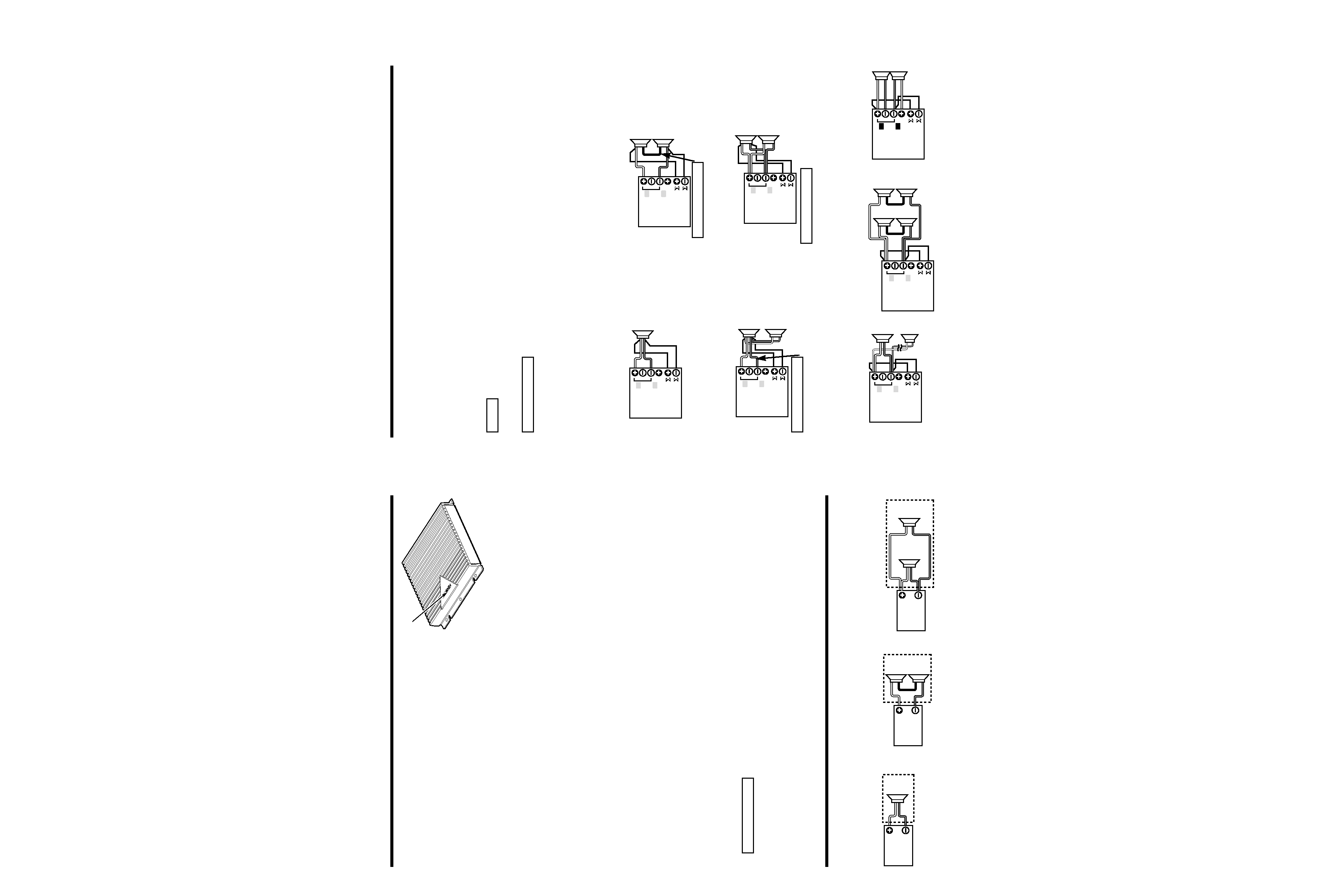
Combined Impedance
s Basic connection
s Series connection
s Parallel connection
4
4
8
4
4
2
4
4
Refer to the diagrams below and ensure that the combined impedance is 2
or greater for
stereo connections and 4
or greater for bridged connections.
BRIDGED
SERVO
FEED BACK
L
R
Sigma servo feed back
BRIDGED
SERVO
FEED BACK
L
R
The sound reproduced through conventional amplifiers is distorted due to the counterelectromotive
force produced in the oscillating system of the speaker. The counterelectromotive force is
particularly high with the woofer which requires a large drive mass.The sigma servo connection
reduces distortion caused by the counterelectromotive force by including the circuit up to the
speaker terminals in the negative feedback loop. This makes it possible to drive speakers with
more fidelity to the input signals and create a sharp bass sound image with few feeling of noise
interference.
The aforementioned effects will not be obtained when the sigma servo connection has not been
made.
The speaker cable and the sigma servo cable should be wired to run along the same route. Note
that this wiring should be separated from the power supply cable.
· The SIGMA SERVO FEEDBACK terminals should be connected properly. Failure to connect
them properly will be the cause of breakdown.
· The rated input of the speakers connected to this unit should be no less than the maximum
output of the amplifier. Otherwise malfunction may result.
Be specially careful in this when connecting speakers in a parallel configuration.
· Speakers that are to be used for bridged connections to this unit should have an impedance of
4
or greater. When connecting multiple speakers, ensure that the combined impedance is 4
or greater. Connection of speakers of less than 4
will be the cause of breakdown.
2CAUTION
NOTE
BRIDGED
SERVO
FEED BACK
L
R
s Basic sigma servo connection
s Series connection
Make this cable as short as possible.
2CAUTION
s Parallel connection (1)
The speaker cables connected to this unit
should be thick enough to supply the
current capacity of two speakers.
2CAUTION
This connection is possible only when the
speakers are identical and the speaker cables
are also of the same type and length.
2CAUTION
s Stereo Connections When the Aforementioned Connections Are Not
Possible
s Parallel connection (2)
BRIDGED
SERVO
FEED BACK
L
R
BRIDGED
SERVO
FEED BACK
L
R
SERVO
FEED BACK
BRIDGED
L
R
BRIDGED
SERVO
FEED BACK
L
R
L
L
R
R
LINE IN
P.CON(REMOTE)
GND
MONO
LINE OUT
25Hz
15Hz
INFRASONIC
FILTER
OFF
OPERATION
MONO
STEREO
OPERATION
MONO
STEREO
25Hz
15Hz
INFRASONIC
OFF
LPF
OFF
HPF
FILTER
LPF
OFF
HPF
CONTROL
INPUT
SENSITIVITY(V)
0.2
5
0.5
1
2
FREQUENCY(Hz)
FREQUENCY(Hz)
50
70
100
LPF 200
170
120
50
70
200
150
120
100
HPF
150
3
4
INPUT
SELECTOR
B
B
B
A
A
A
A
A
+
(MAX)
(MIN)
INPUT
SENSITIVITY(V)
0.2
5
0.5
1
2
3
4
(MAX)
(MIN)
CONTROL B
50
70
100
LPF 200
170
120
50
70
200
150
120
100
HPF
150
LEFT
BRIDGED
SERVO
FEED BACK
RIGHT
SPEAKER OUTPUT
FUSE(20A
×4)
BATT.
GND
B
B
B
A
A
A
2
0
2
0
2
0
2
0
-
+
English
9
8 English
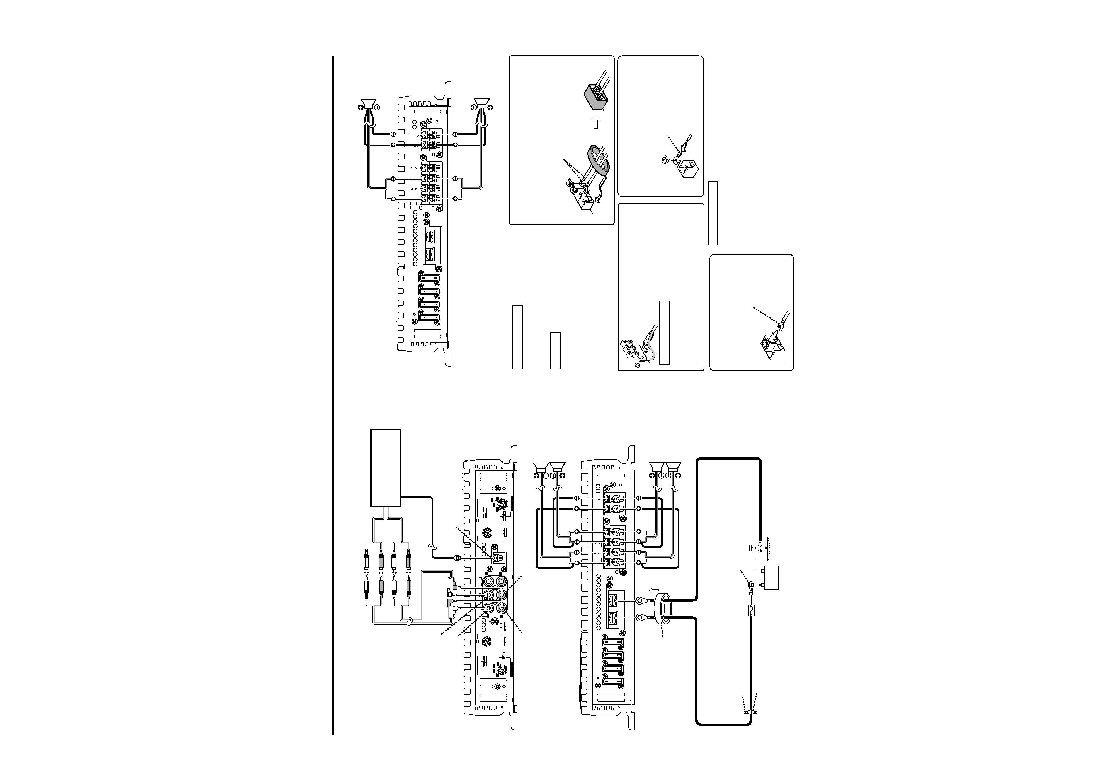
Connection
LEFT
BRIDGED
SERVO
FEED BACK
RIGHT
SPEAKER OUTPUT
FUSE(20A
×4)
BATT.
GND
B
B
B
A
A
A
2
0
2
0
2
0
2
0
s Bridged Connections
s Power and Speakers cable connection (Stereo Connections)
CENTER UNIT
(Cassette receiver,
CD receiver, etc.)
RCA cable (Commercially
available part)
A Left input (White)
A Right input (Red)
B Left input (White)
B Right input (Red)
RCA cable ground terminal
When using an RCA cable with
a ground lead attached, connect
the ground lead to this terminal.
ALINE IN (Front)
BLINE IN (Rear)
Do not use this terminal for power source
grounding. This unit will be damaged if the
power source grounding wire is connected to
this terminal.
2CAUTION
Front left
speaker
Rear left
speaker
Rear right
speaker
Front right
speaker
Battey
Power control (REMOTE)
lead terminal
To prevent fire caused by a short in the
wiring, connect a fusible link or breaker
nearby the battery's positive terminal.
Connect the ground cable to a metal part of
the car chassis that acts as an electrical
ground passing electricity to the battery`s
negative - terminal. Do not turn the power
on if the ground cable is not connected.
NOTE
2WARNING
· If a buzzing noise is heard from the speakers when the engine is running,
connect a line noise filter (optional) to each of the battery cable.
· Do not allow the cord to directly contact the edge of the iron plate by using
Grommets.
Terminal cover
Fire wall
Grommets
Ground cable (Commercially available part)
Battery cable (Commercially
available part)
Round terminal (Large)
Power terminal
Pass battery and ground cables through supplied
terminal cover and connect to respective
terminals. After completing connections, fasten
terminal cover over terminal bracket.
Round terminal (Medium)
A Bridged
B Bridged
s Connection Precautions
Speaker Output/Sigma Servo
Feedback Terminals
Connect the speaker output
cables to these terminals.
Lead terminal
(Commercially
available part)
Power control lead terminal
Connect the Center units's power
control lead from the center unit.
Round terminal
(Small)
· Speakers that are to be used for stereo connections to
this unit should have an impedance of 2
or greater.
When connecting multiple speakers, ensure that the
combined impedance is 2
or greater. Connection of
speakers of less than 2
will be the cause of breakdown.
· Speakers that are to be used for bridged connections to
this unit should have an impedance of 4
or greater.
When connecting multiple speakers, ensure that the
combined impedance is 4
or greater. Connection of
speakers of less than 4
will be the cause of breakdown.
2CAUTION
Power control cable
(Commercially
available part)