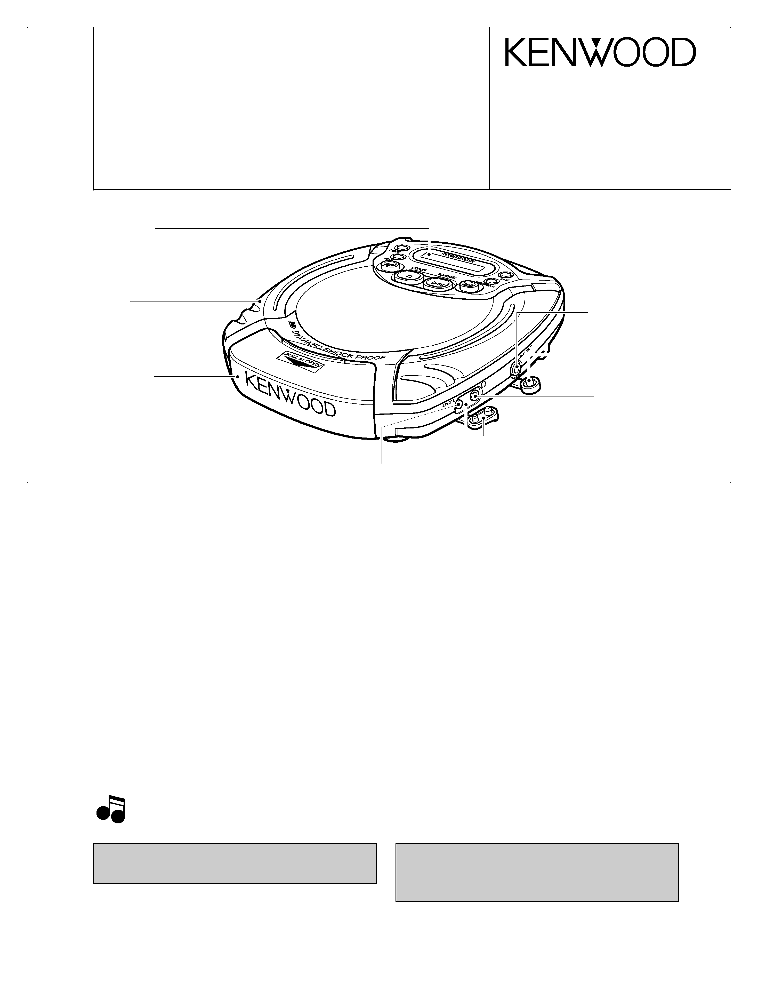
PORTABLE CD PLAYER
DPC-885
SERVICE MANUAL
© 1997-9/B51-5352-00 (K/K) 3447
Front glass
(B10-2397-04)
Holder
(J19-5841-03)
Cap
(F09-0133-04)
Electric circuit module
(W02-2527-05)
Cover *
(F07-)
Miniature phone jack
(E11-0278-05)
Cap
(F09-0132-04)
Packing
(G53-0073-04)
Miniature phone jack
(E11-0371-05)
[ Format ]
System.....................................................................................................................................Compact disc digital audio system
Laser .............................................................................................................................................................Semiconductor laser
[ Audio ]
Frequency response ..................................................................................................................................20 Hz ~ 20 kHz, ±3 dB
Headphone output (16
, 1 kHz) ........................................................................................................................10 mW + 10 mW
(Headphone output level / impedance .........................................................................................................max. 450 mV / 2.2
)
[For CHINA and Duty Free Shop in JAPAN]
Digital output optical....................................................................................................-21 dBm ~ -15 dBm (wave length 660 nm)
[For other countries]
LINE output level/impedance ..................................................................................................................................550 mV/702
[ Power supply ]
External DC supply....................................................................................................................................................DC 4.5 ~ 6 V
Rechargeable batteries (NB - 130) x 2............................................................................................................................DC 2.4 V
Commercially-available alkaline batteries (LR6/AA) x 2....................................................................................................DC 3 V
Battery life (continuous repeat playback)
(Figures inside parentheses are the values when D.A.S.C. is ON.)
Commercially-available alkaline batteries (LR6/AA) x 2 ..........................................................................Approx. 17.5 (15) hours
Rechargeable batteries (NB-130) x 2.......................................................................................................Approx. 9.0 (8.0) hours
Dimensions (W x H x D) ...................................................................................132mm x 32mm x 153mm (5 - 3/16" x 1 - 1/4" x 6")
Weight (net)................................................................................................................................................................270 g (9.5 oz.)
SPECIFICATIONS
1. KENWOOD follows a policy of continuous advancements in development. For this reason specifications may be changed without
notice.
2. Sufficient performance may not be exhibited at extremely cold locations (where water freezes.).
Notes
Illustration is K type.
* Refer to parts list on page 17.
In compliance with Federal Regulations, following are
reproductions of labels on, or inside the product relating to laser
product safety.
KENWOOD-Crop. certifies this equipment conforms to DHHS
Regulations No. 21 DFR 1040. 10, Chapter 1, Subchapter J.
DANGER : Laser radiation when open and interlock defeated.
AVOID DIRECT EXPOSURE TO BEAM
COVER/CIR/EXP-INT 98.4.242:57PM y[W 1
DPC-885
2
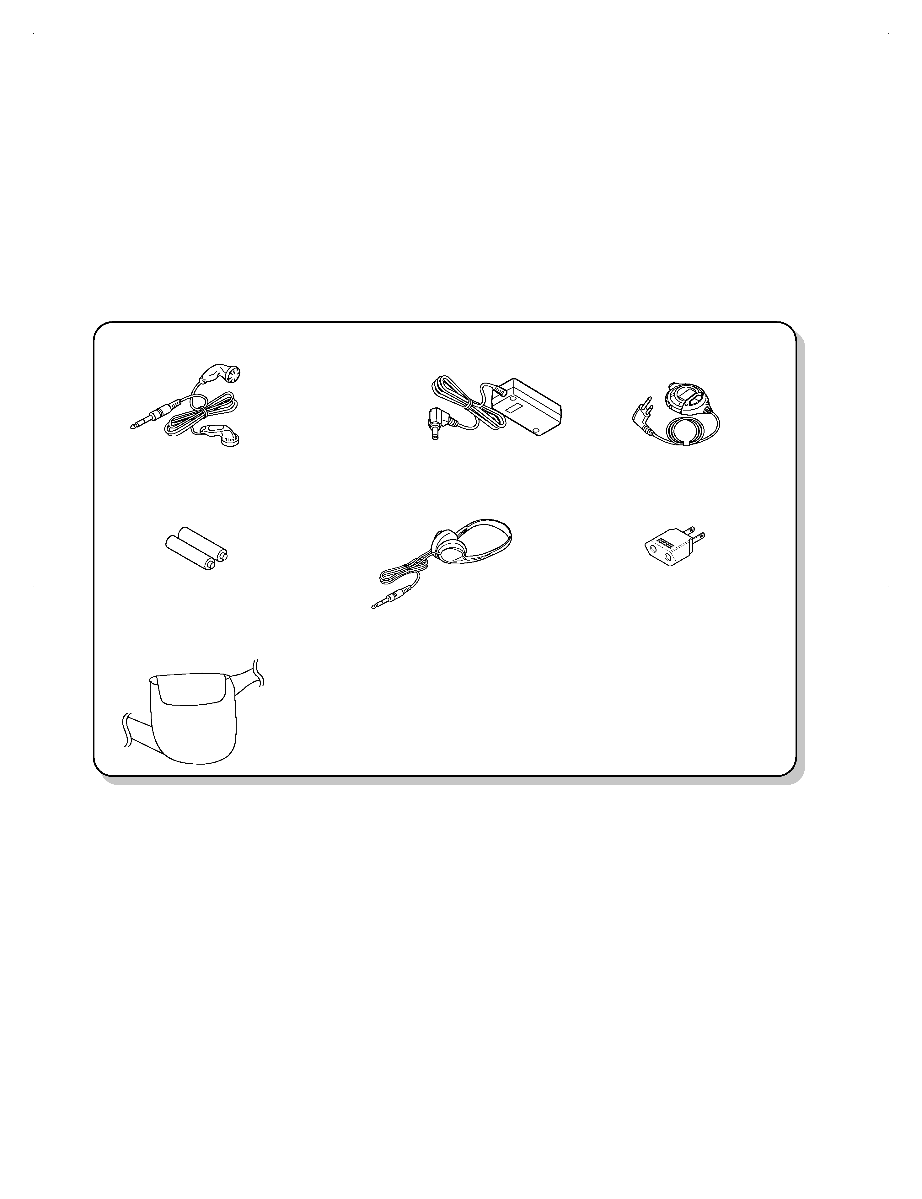
CONTENTS/ACCESSORIES
Stereo headphone.................(1)
(W01-0923-05) : M2
Stereo headphone.................(1)
(W01-0940-05) : KPMTEX
AC plug adapter ....................(1)
(E03-0115-05) : M,M2
Rechargeable battery ...........(2)
(W09-1237-05)
Remote control......................(1)
(A70-1163-05) : MX
(A70-1164-05) : KPET
AC adapter ............................(1)
(W08-0658-05) : E
(W08-0659-05) : T
(W08-0660-05) : X
(W08-0667-05) : M
(W09-1251-05) : KP
Carrying case ........................(1)
(W01-0939-05)
SPECIFICATIONS .........................................Top cover
CONTENTS/ACCESSORIES ......................................2
CIRCUIT DESCRIPTION .............................................3
ADJUSTMENT .............................................................6
PC BOARD ................................................................. 7
SCHEMATIC DIAGRAM ............................................. 9
EXPLODED VIEW .....................................................15
PARTS LIST...............................................................17
Accessories
CONTENTS
COVER/CIR/EXP-INT 98.4.242:57PM y[W 2
DPC-885
3
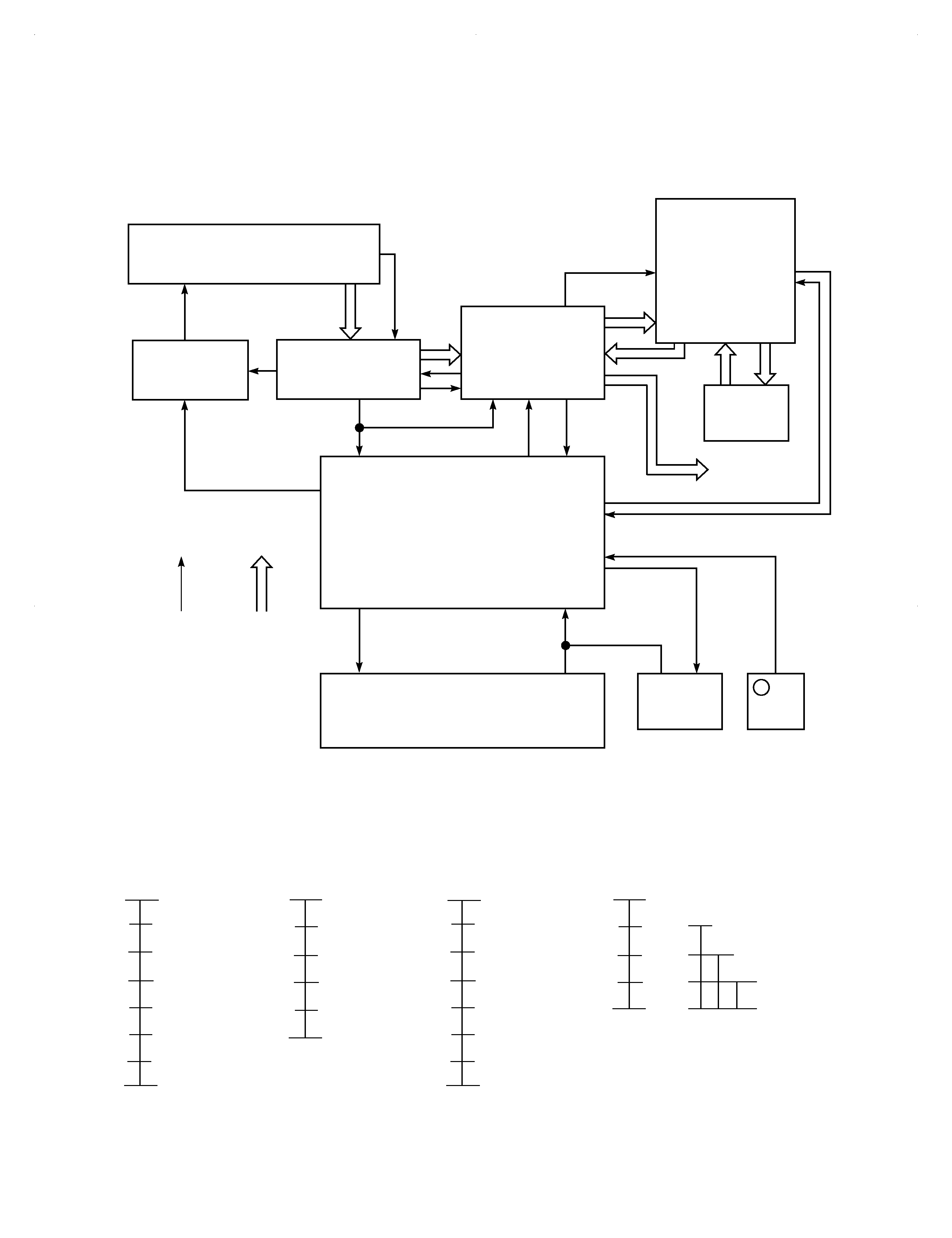
CIRCUIT DESCRIPTION
2.80
2.80
1.97
1.73
1.49
1.21
0.89
0.60
0.00
KEY OFF
DOWN
B.BOOST
UP
STOP
PLAY
KEY OFF
MKEY
V
V
2.80
2.00
1.60
1.20
0.80
0.00
KEY OFF
REPEAT
P.MODE
DASC
KEY OFF
MKEY
V
2.80
1.97
1.73
1.49
1.21
0.89
0.60
0.00
KEY OFF
DOWN
B.BOOST
UP
STOP
PLAY
KEY OFF
MKEY
V
BATT
1.75
1.41
1.13
0.00
OK TO CHARGE
FLASH CHARGE INDICATOR
AUTO POWER-OFF
(IC3, 28Pin)
UNIT KEYS(1)
UNIT KEYS(2)
LCD H/P REMOCON KEYS
BATTERY VOLTAGE
(IC3, 29Pin)
(IC3, 33Pin)
IC3 (31pin, 32Pin)
CD-ASP
CD-DSP+1bitDAC
uPD78063GF-138
LCD+A/D KEY
LCD
KSM542DBA
CXA1982Q
CXD3009Q
RL5C356
8M
D-RAM
u-COM
COM X 4
SEG X 13
A/D KEY
DISPLAY
FOK
IC 6
IC 2
IC 1
IC 3
AUDIO
LINE
1
2
3
4
5
6
7
TRAVERSE UNIT
CONTROL
REMOCON
SENSOR
AUDIO
OUTPUT
SHOCK PROOF
MECHA. DRIVER
LINE
1. Main microprocessor : µPD78063GF-138 (X32-, IC3)
1-1 Microprocessor periphery block diagram
1-2 A/D converter
COVER/CIR/EXP-INT 98.4.242:57PM y[W 3
DPC-885
4
CIRCUIT DESCRIPTION
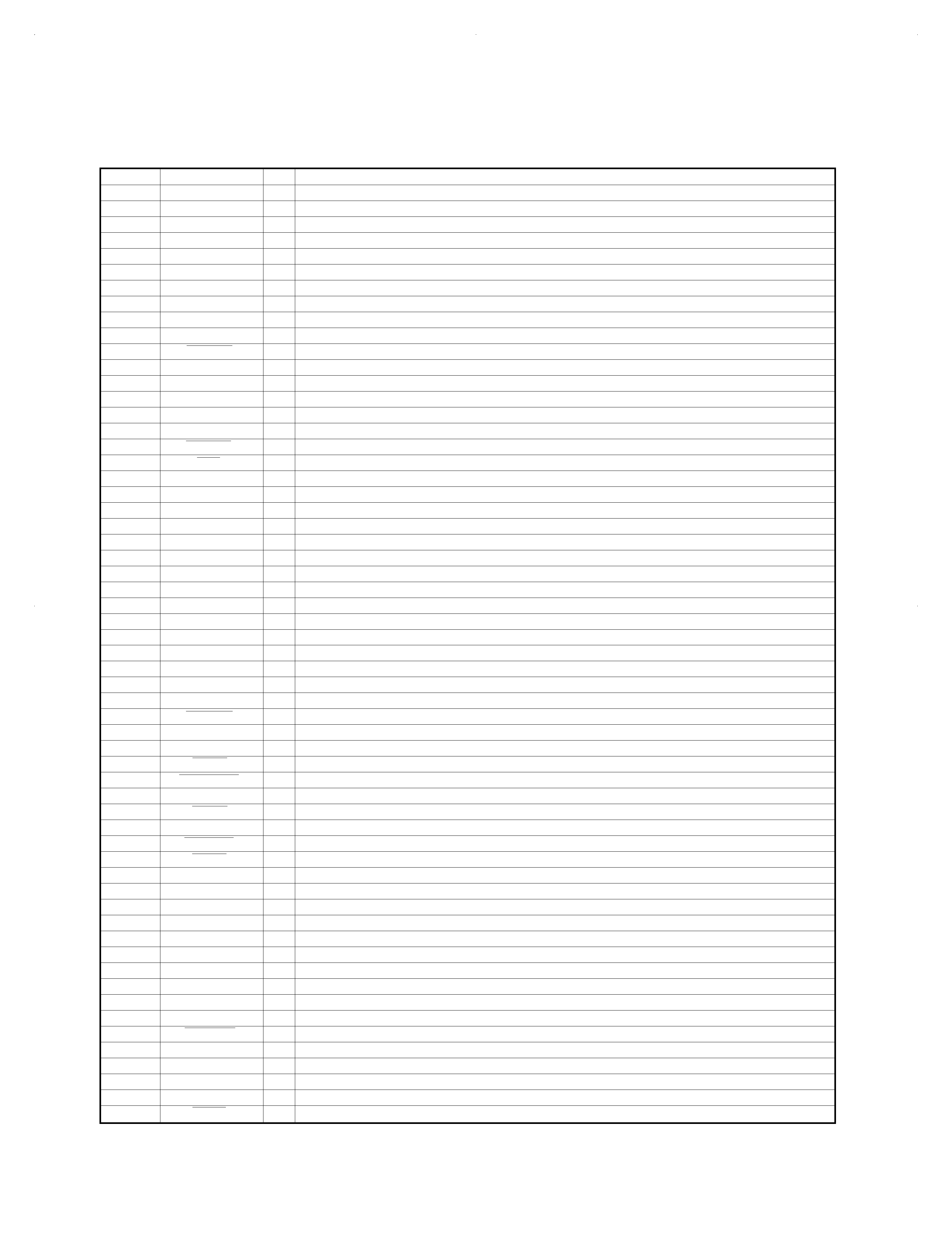
1-3 Pin description microprocessor : µPD78063GF-138 (X32-, IC3)
Pin No.
Name
I/O
Function
1
NC
I
Not used
2
SQCK
O
Clock output for Q-data input of CXD3009Q
3
SDTO
O
DATA input to RL5C356
4
SDTI
O
DATA output to RL5C356
5
SCK
O
CLOCK output to RL5C356
6
IC
Connected to VSS
7,8
X2,1
Connected to oscillator (5.00MHz)
9
VDD
Power supply
10
XT1
Connected to GND
11
XT2
Not used
12
RESET
I
Microprocessor reset
13
SCOR
I
Interruption of fall edge of SCOR
14
RCI
I
Remote control input
15
NC
Not used
16
FOK
I
Focus clock detection terminal (CXA 1982Q)
17
GFS
Not used
18
HDATA
O
Output terminal for LCD remocon display
19
B.B
O
For bass boost control
20
SGAIN
Not used
21
CHDT
I
Data comparator monitor input for RL5C356
22
XSOE
O
Serial data output permission signal for RL5C356
23,24
NC
Not used
25
DEFECT
O
Mirror bottom-hold-enable
26
NC
Not used
27
AVSS
Connected to GND
30
VOL
I
Volume level input of main unit
28,29
KEY1,KEY2
I
Key input from main unit or wired remote control
31,32
BATTV1,2
I
Detection of voltage level on rechargeable battery
33
HP KEY
I
HP Key input terminal for display
34
NC
Not used
35
ADON
O
A/D converter on/off
36
AVDD
Analog power supply for A/D converter
37
AVREF
Reference voltage input for A/D converter
38
SLTSW
I
Start limit switch of pickup
39
DCDC ON
O
DC/DC converter control (H:ON, L:OFF)
40
VSS
GND
41
ADPT
I
Adaptor detection (H:OFF, L:ON)
42
CHRGOK
I
Voltage level of rechargeable battery detection (H:NG, L:OK)
43
CHRG
O
Charge power supply
44
XRST
O
IC reset output terminal (CXA1982Q, CXD3009Q, RL5C356)
45
DMUTE
O
Motor drive mute output terminal
46
RMUTE
O
Analog mute output
47
TEST
I
For test mode
48
NC
Not used
49
PSW
O
Headphone amp control
50
HPMUTE
O
Mute output terminal for LCD remocon
51~54
COM0-3
O
Common signal output for display
55
BIAS
O
Bias input for display
56-58
VLC0-2
O
External resistor connected to power supply for dividing display
59
VSS
GND
60~74
S0~S14
O
Segments signal output for display
75~83
NC
Not used
84
LED
O
Power supply ON/OFF for optical output
85
SHOCK
O
Shock proof on/off (CXD3009Q) D.A.S.C. ON : L
86
XLAT
O
LATCH output to CXD3009Q
87
CLK
O
CLOCK output to CXD3009Q
88
DATA
O
DATA output to CXD3009Q
89
SENS
I
SENS input from CXD3009Q
90
PLUG
I
Remocon data input terminal
COVER/CIR/EXP-INT 98.4.242:57PM y[W 4
DPC-885
5
CIRCUIT DESCRIPTION
Pin No.
Name
I/O
Function
91
LINE
I
Line out detection terminal
92
HOLD
I
HOLD switch on/off
93
LD
O
Laser diode output terminal
94
LIDSW
I
Cover open detection switch
95
XWIH
O
Write permission signal output for RL5C356
96
XEMP
I
Read prohibition signal input for RL5C356
97
XWRE
I
Write prohibition signal input for RL5C356
98
XQOK
O
CD sub code Q OK signal output for RL5C356
99
XLT
O
LATCH output to RL5C356
100
SQSO
I
CDQ code data input from CXD 3009Q
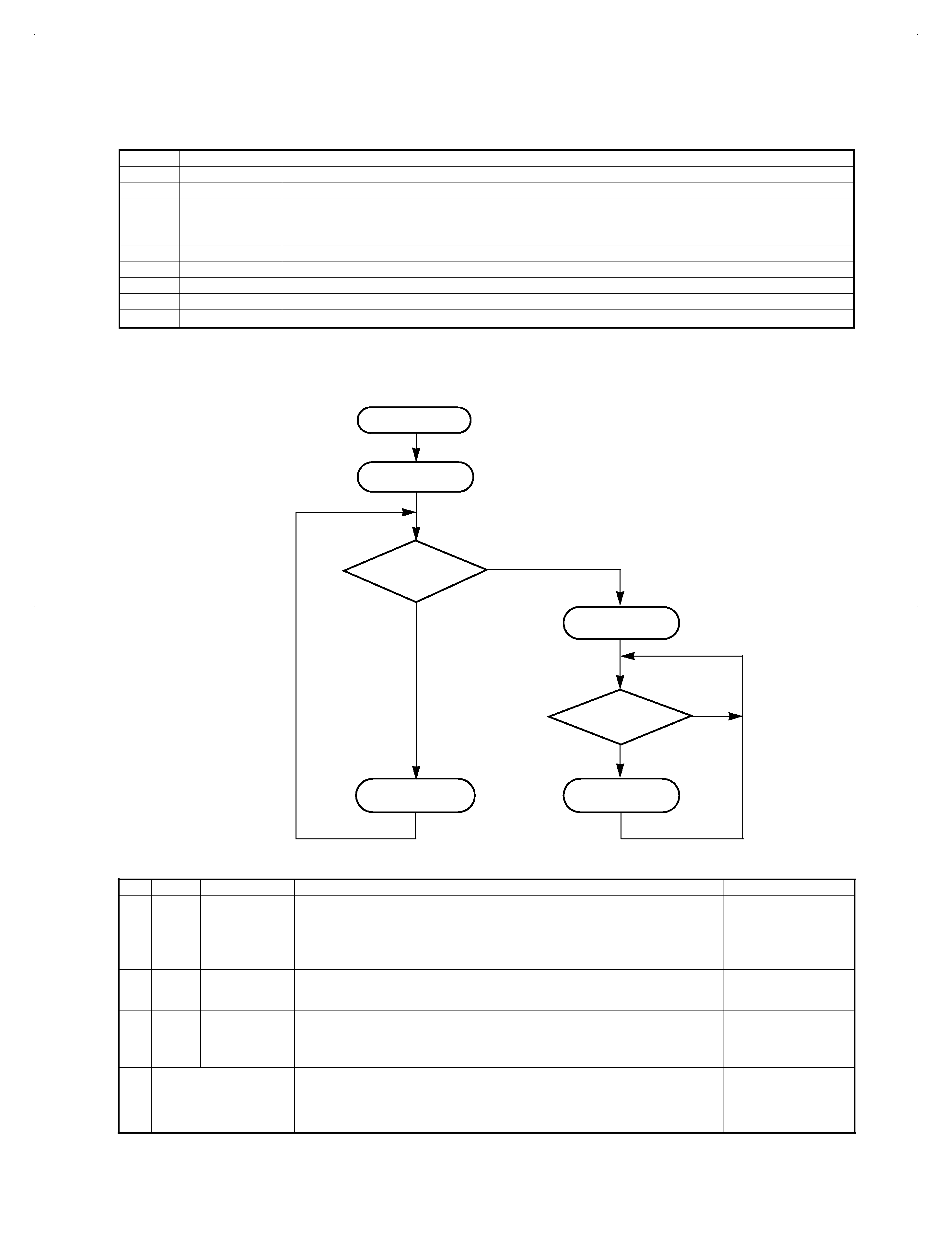
2. Test Mode
2-1 Setting the test mode
This model can be set to the test mode by shorting
the test-land of the X32 board.
START
Turn on lid
switch
Is test land
shorted?
Test mode
processing
Is key pushed?
Track No. "01"
is displayed.
TEST MODE
YES
NO
NO
See following table.
Normal operation
No.
Mode
Key Name
Function
TRACK No. display
1
05
PLAY/PAUSE
(
6)
1. Focus servo.....................................................................................................ON
2. Tracking servo.................................................................................................ON
3. Feed servo ......................................................................................................ON
Absolute time at position of limit SW is displayed in time area, then play is started.
05
After 1, 2 and 3 are
finished, track No.
played currently and its
play time are indicated.
2
03
UP
(
¢)
1. Focus servo.....................................................................................................ON
2. Tracking servo...............................................................................................OFF
3. Feed servo ....................................................................................................OFF
03
3
01
STOP
(
7)
1. Focus servo...................................................................................................OFF
2. Tracking servo...............................................................................................OFF
3. Feed servo ....................................................................................................OFF
( Test mode can be can celled while pressing the STOP (
7) Key in 01 mode.
01
4
While pressing the
P. MODE/SEARCH Key,
turn the AC ON
All LCD is turned ON for 2 seconds.
ó
All LCD is turned OFF for 2 seconds.
ó
Returned to normal mode.
--
2-2 Key and functions avild in test mode
COVER/CIR/EXP-INT 98.4.242:57PM y[W 5