note: This manual is not available for U.S.A and canada market.
DVD / AV RECEIVER
DVR-6100/6100K
SERVICE MANUAL
(DVT-6100)
© 2002-7 PRINTED IN KOREA
B51-5803-00 (K/K) 2196
MENU
STOP
PLAY/PAUSE
INPUT
76
0
ON SCREEN
VOLUME
OPEN/CLOSE
POWER
-ON/OFF
STANDBY
ACTIVE EQ
ENTER
MIC
LEVEL
CS II
TOP MENU/BAND
DSP
PRO LOGIC II
DOLBY DIGITAL
DTS
PHONES
(OPTICAL)
VIDEO
AUDIO
R
L
FRONT AUX
DIGITAL
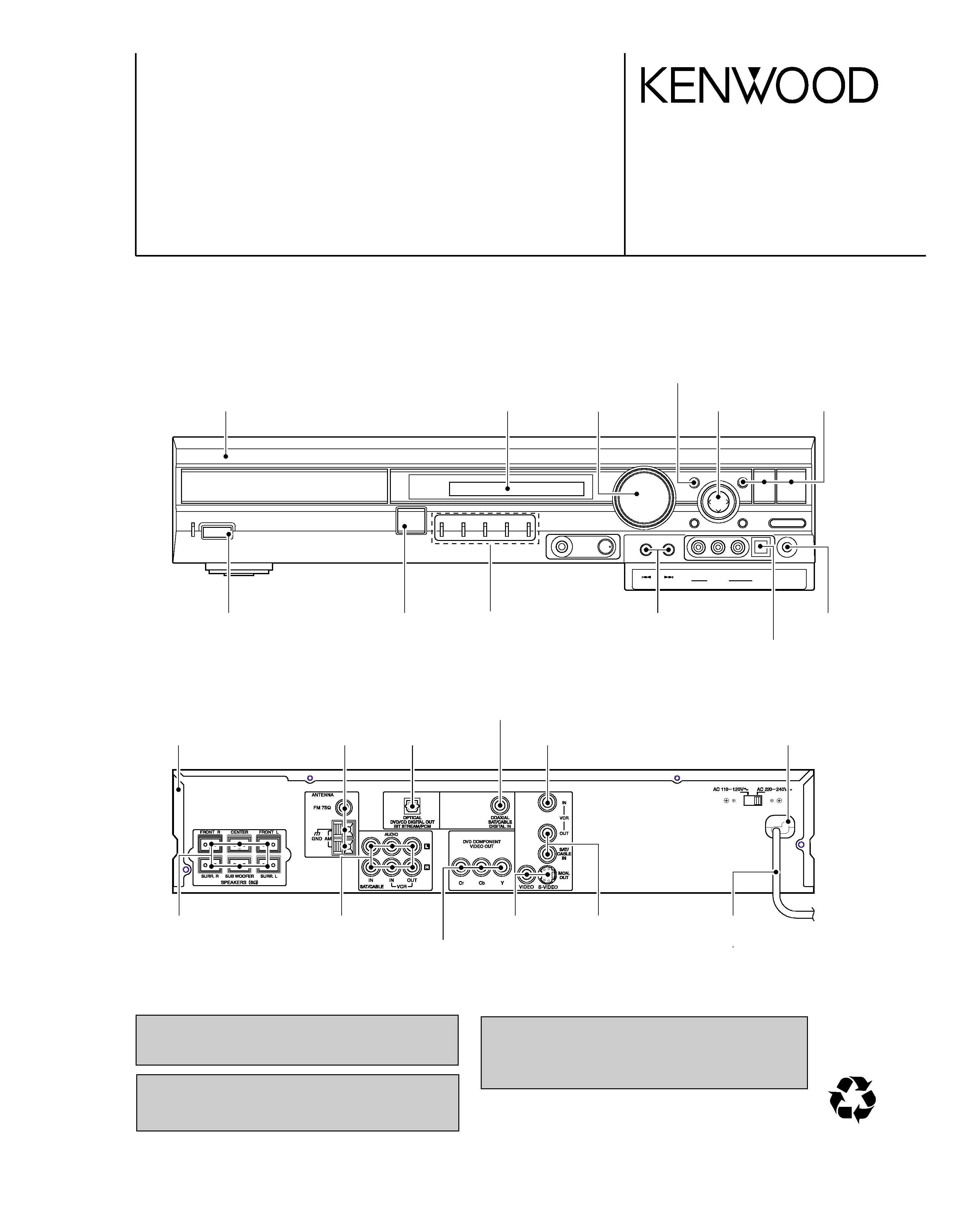
DEC cabinet *
(B07-)
DEC crystal
(B10-3900-08)
Con DIN socket
(E63-1243-08)
Con phono socket
(E63-1290-08)
Con phono socket
(E63-121-08)
Pun cover
(A01-3863-08)
In compliance with Federal Regulations, following are repro-
duction of labels on, or inside the product relating to laser
product safety.
KENWOOD Corp. certifies this equipment conforms to DHHS
Regulations No.21 CFR 1040. 10, Chapter 1, subchapter J.
DANGER : Laser radiation when open and interlock defeated.
AVOID DIRECT EXPOSURE TO BEAM.
Caution : No connection of ground line if disassemble
the unit. Please connect the ground line on
rear panel, PCBs, Chassis and some others.
DEC button
(K29-8255-08)
DEC button
(K29-8256-08)
DEC button
(K29-8251-08)
DEC button
(K29-8250-08)
Tuner ass'y *
(W02-)
MLD clamp
(J42-0350-08)
D-REM
(W02-2911-08)
Con phono socket
(E63-1244-08)
Conn-speaker
(E70-0165-08)
Con phono socket
(E63-1270-08)
DEC button
(K29-8254-08)
Phone jack
(E11-0957-08)
MLD indicator
(B10-3897-08)
IC-opt
(W02-2961-08)
DEC knob
(K29-8249-08)
DEC button
(K29-8253-08)
Con phono socket
(E63-1289-08)
Wire-MCRDM *
(E30-)
Illustration is DVR-6100K.
* Refer to parts list on page 37.
70%
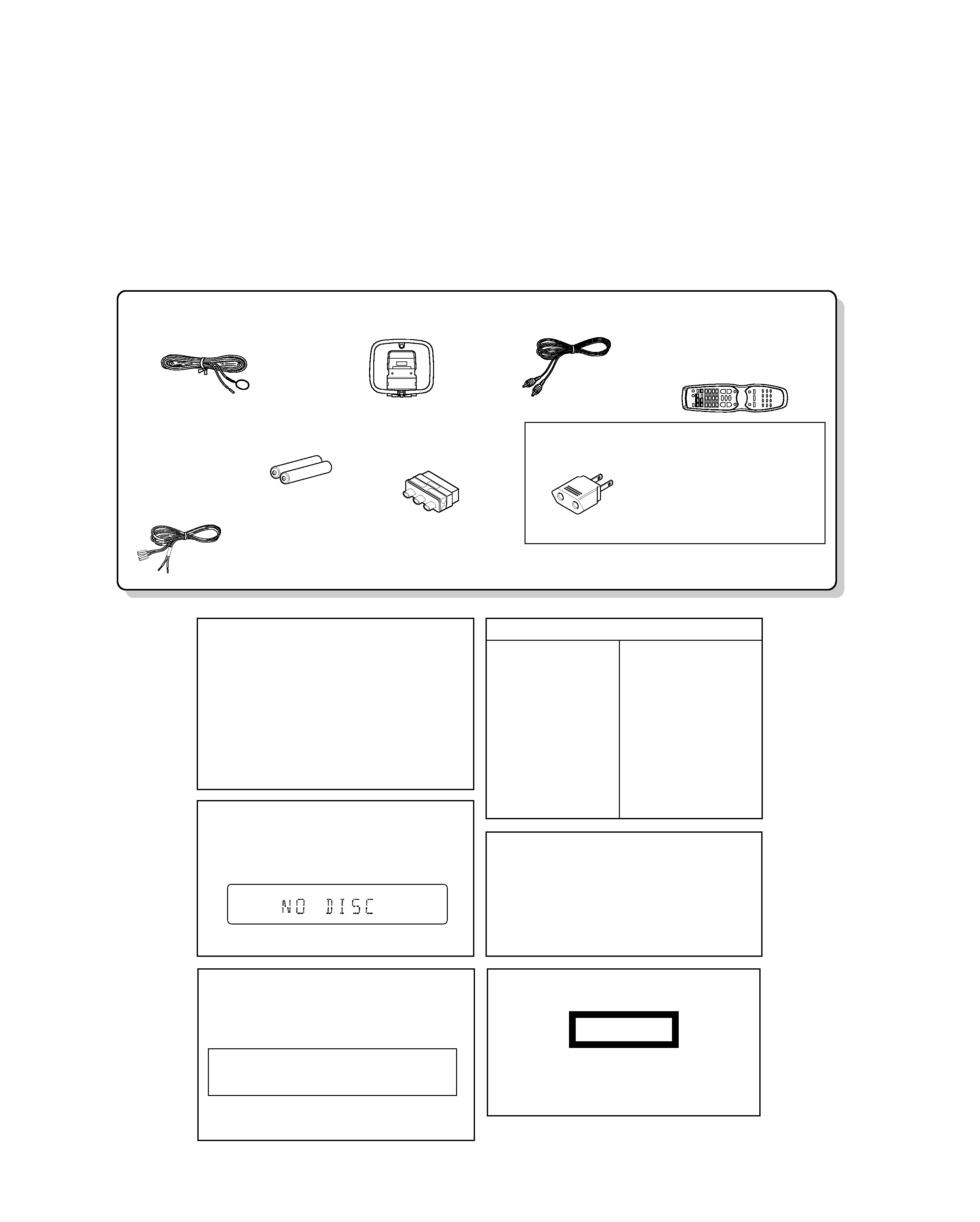
*AC Plug Adaptor (1) *
(E03-0115-05)
Use to adapt the plug on the
power cord to the shape of the
wall outlet.
(Accessory only for regions where
use is necessary.)
FM indoor antenna (1)
Loop antenna (1)
Remote control unit (1)
Batteries (R6/AA) (2)
V ideo cord (1)
SCART plug adaptor (1)
(Europe and U.K. only)
(E69-0012-05)
Speaker cords (6)
(T90-0882-08)
(A70-1607-08): KP
(A70-1608-08): YX
(A70-1609-08): ET
(A70-1610-08): MM2H
(E30-7265-08): RED
(E30-7283-08): GREEN
(E30-7284-08): BLUE
(E30-7285-08): VIOLET
(E30-7269-08): GREY
(E30-7286-08): WHITE
(T90-0896-08)
(E30-1427-05)
Caution on condensation
Condensation (of dew) may occur inside the unit when there is
a great difference in temperature between this unit and the out-
side.
This unit may not function properly if condensation occurs. In
this case, leave the unit for a few hours, and restart the opera-
tion after the condensation has dried up.
Be specially cautious against condensation in a fol-
lowing circumstances:
When this unit is carried from one place to another across a large
difference in temperature, when the humidity in the room where
this unit is installed increases, etc.
Stored contents which are
cleared in at least a week after
power plug is unplugged from
power outlet.
Amplifier section
Last input selection
Volume control value
Surround setting
ACTIVE EQ
Tuner section
Receiving band
Frequency
Preset stations
Tuning mode setting
DVD section
Menu setup
Power status
Memory backup function
WARNING NOTICE:
IN MOST CASES IT IS AN INFRINGEMENT OF COPY-
RIGHT TO MAKE COPIES OF TAPES OR DISCS WITH-
OUT THE PERMISSION OF THE COPYRIGHT OWN-
ERS. ANYONE WISHING TO COPY COMMERCIALLY
AVAILABLE TAPES OR DISC SHOULD CONTACT THE
MECHANICAL COPYRIGHT PROTECTION SOCIETY
LIMITED OR THE PERFORMING RIGHTS SOCIETY LIM-
ITED.
Note related to transportation and movement
Before transporting or moving this unit, carry out the
following operations.
1 Remove the disc from the unit.
2 Press the 6 key.
3 Wait a few seconds and turn the unit OFF.
Operation to reset
The microcomputer may fall into malfunction (impossibility
to operate, erroneous display, etc.) when the power cord is
unplugged while power is ON or due to an external factor. In
this case, execute the following procedure to reset the
microcomputer and return it to normal condition.
÷ Please note that resetting the microcomputer clears the
contents stored in and returns and to condition when it left
the factory.
Set the POWER switch to ON (set to Standby mode).
Then press the
¢ key, 4 key and STOP key in this
order.
The marking this product has been classified as Class
1. It means that there is no danger of hazardous radia-
tion outside the product.
Location: Back panel
CLASS 1
LASER PRODUCT
The marking of products using lasers
(Except for some areas)
DVR-6100/6100K
2
CONTENTS / ACCESSORIES / CAUTIONS
CONTENTS / ACCESSORIES / CAUTIONS ............. 2
DISASSEMBLY FOR REPAIR....................................3
BLOCK DIAGRAM ......................................................4
CIRCUIT DESCRIPTION ............................................5
WIRING DIAGRAM ...................................................14
PC BOARD .............................................................. 15
SCHEMATIC DIAGRAM .......................................... 24
EXPLODED VIEW ....................................................36
PARTS LIST..............................................................37
SPECIFICATIONS ......................................Back cover
Contents
Accessories
Cautions
DVR-6100/6100K
3
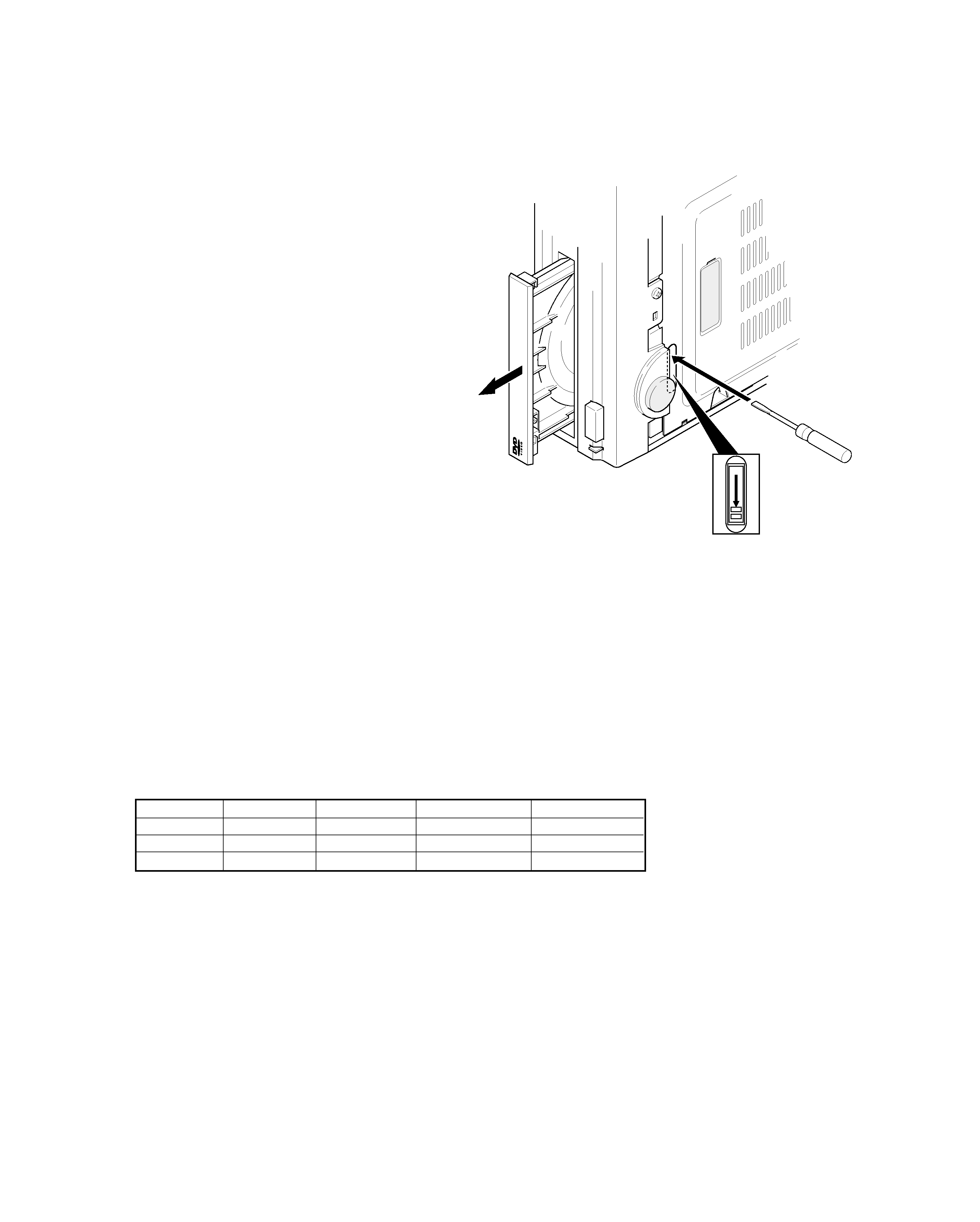
DISASSEMBLY FOR REPAIR
How to open the tray if it does not come out.
1. Insert a flat driver in the drawing through the hole on the load-
ing chassis bottom and pull the lever down.
2. Pull out the tray frontward by hand when it comes just out.
SYSTEM
RECEIVER
SPEAKERS
SUB WOOFER
DESTINATIONS
DVT-6100
DVR-6100
KSW-6100
-
E,T,X,Y,M
DVT-6100K
DVR-6100K
KSW-6100
-
M,H
DVT-6100K
DVR-6100K
KSW-6100
-
M2(UAE)
SYSTEM CONFIGURATION
DVR-6100/6100K
4
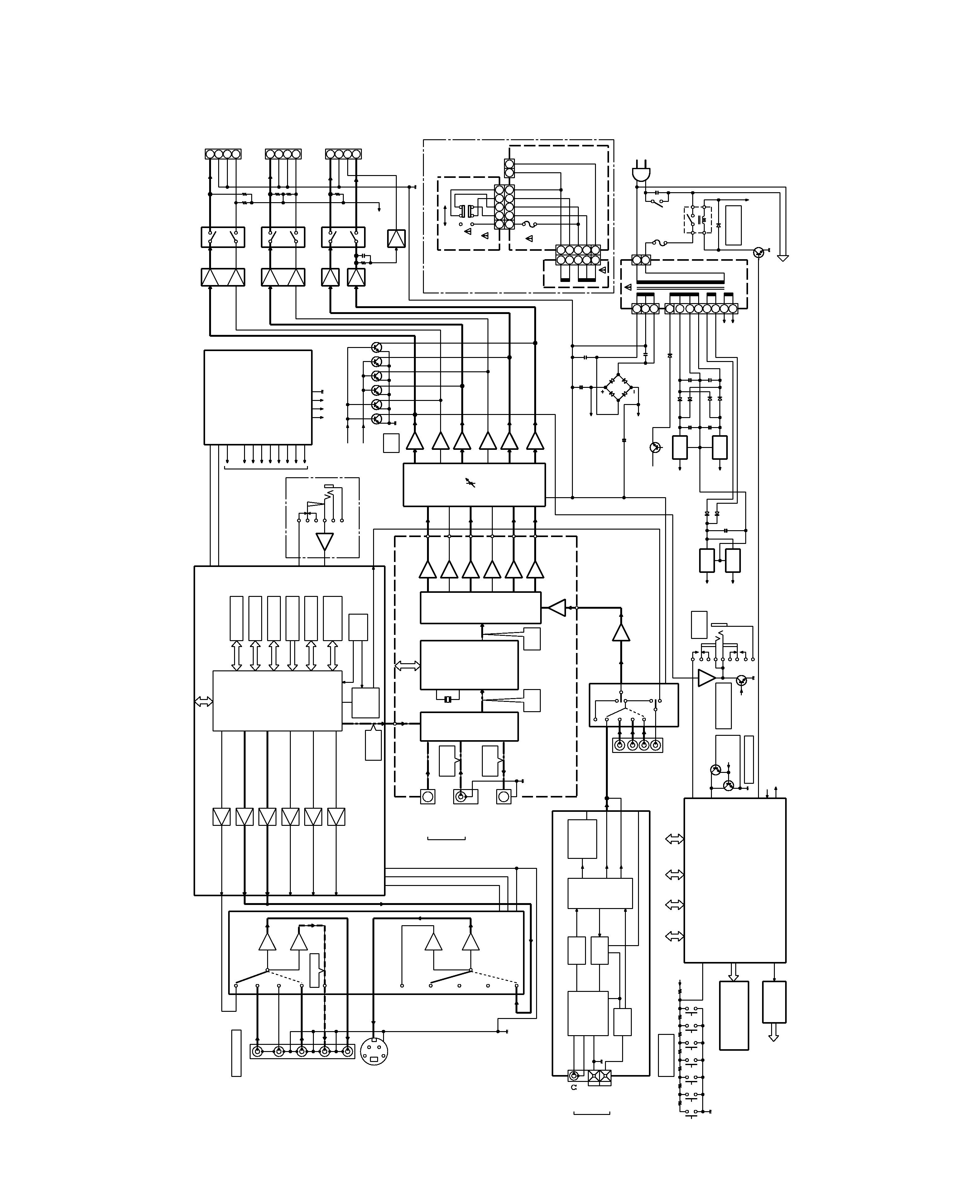
BLOCK
DIAGRAM
D GND
6dB
6dB
C-VIDEO
DVD
S-VIDEO
6dB
6dB
DVD
AGND
-5.6V
+5.6V
COMPOSITE
R(CR)
B(CB)
G(Y)
C
Y
+5.6V
-5.6V
AGND
R(CR)
B(CB)
G(Y)
C
Y
CVBS
FROM SYSTEM u-COM
27MHz
DAC MCLK
MIC IN
MGND
DGND
+5.6V
SPDIF
DGND
MGND
+5VA
AGND
+12VA
-5VA
+3.5V
+2.5V
+5V
+5.5VS
+9VM
+12VM
to
DVD & VIDEO
GND
P/C
5.5VS
P/D
to FRONT
LPF
LPF
LPF
LPF
LPF
LPF
INPUT
12.28MHz
SDATAN1
SW
CT
SR
SL
FR
FL
DVD
FROM SYSTEM u-COM
SW
CT
SR
FR
SL
FL
SW
CT
SR
SL
FR
FL
CHGND
AM OSC
FM OSC
22
4
DGND
AGND
TUNER-L
TUNER-R
to u-COM
AGND
BUFFER
RDS DATA/CLK
GND
GND
8
4
5
7
1
2
3
1
2
3
1
2
F201
SK21
ST-BY +5V
AC INPUT FOR SMPS
AC2
AC1
+
VEE
VDD
+
FL AC
FL AC
FUNCTION SECTION
CONTROL
SECTION
VOLUME/TONE
TUNER
DVD
CONTROL
LED
CE,CLK,DATA
4094
+5V
A/D INPUT
P/C
RDS DATA/CLK
POWER DOWN
TO SMPS
DETECT
DC
PROTECT
DGND
HEADPHONE
DETECT
H/P MUTE
17dB
C/S
MUTE
SUB WOOFER
W/F
MUTE
-29.5V
29.5V
MIC DET
+
+
-27V
FL
+
6
DC PROTECTION
S/W
CENTER
S/W
GND
SR
SL
FR
GND
FL
1
5
3
2
4
15
3
24
12
5
34
12
F252
1
5
3
2
4
230V
115V
GND
GND
GND
+3.3V
+5V
+15V
-15V
AV AUX(FRONT)
SAT/CABLE
VCR OUT
VCR IN
MONITOR
MONITOR
VIDEO
SWITCHING
IC61
MPEG
PROCESSOR
SDRAM
FLASH
EEPROM
ADC
MECHANISM
CONTROL
LOAD
PLL IC
DAC
AUDIO-
IC64
SECTION
DVD
SMPS FOR
DVD & VIDEO
FOR DVD
AC INPUT
AUX(F)
SAT/
OPTICAL
OPTICAL
OUTPUT
DIGIT
A
L
INPUT
(OPTICAL)
DIR
AUDIO
DIGITAL
ADC &
DAC
IC33
IC31
IC39
IC37,38
IC11
VOLUME &
MASTER
TONE
CIRCUIT
IC15-B
IC15-A
IC16-B
IC16-A
IC17-B
IC17-A
GND
AM
FM75
ANTENNA
AM RF
FRONT-END
FM
IF AMP
FM/AM
DECODER
RDS
IF+MPX
PLL
TUNER MODULE
VCR IN
VCR OUT
AUX/FRONT
SAT/CABLE
IC14
IC13
AUDIO
SWITCH
N112
N111
P2
AC INPUT
STAND -BY
CONTROL
Q251
D22
IC51
SYSTEM u-COM
HNV-11SM18
FL DISPLAY
IC81
REGISTER
SHIFT
FRONT KEY
FUNCTION
NJ83
PROTECTION
Q24,25
HEAD-
PHONE
IC12
HEADPHONE
AMP
VIDEO INPUT
Q30,31
REC OUT
DIGITAL
IN
DATA
DATA
DIGITAL
DATA
CABLE
PROCESSOR
DIGITAL
OUT
(ASSY)
MIC JACK
IC82
MIC AMP
(M) TYPE ONLY
IC34-B
IC34-A
IC36-B
IC36-A
IC35-B
IC35-A
Q23
IC23
+15V
D30
D29
D28
D27
-15V
IC24
+3.3V
IC25
D24
D23
IC26
+5.0V
IC21
IC20
IC19
IC18
NJ11-C
NJ11-B
NJ11-A
IC22
SPKR
RLYSK13
RLYSK12
SPKR
SPKR
RLYSK11
N251
P2
N252
P252
(M,M2,Y) TYPE ONLY
LOOP
S-VIDEO
NJ34
NJ35
OUT
OUT
PRE
AMP
P251
SURROUND
DSP B'D
DVR-6100/6100K
5
CIRCUIT DESCRIPTION
Pin No.
Pin Name
I/O
Pin Description
PIOs and communication
1
PIO2(5) RGB SEL(BLANK)
I/O
RGB sel (blank). unused
2
PIO2(6) VIDEO MUTE
I/O
Video mute control.
3
PIO2(7) 16: 9 INDICATOR
I/O
16 : 9 indicator (unused).
6
PIO3(0) SCART H (TV/AUX)
I/O
Unused.
7
PIO3(1)
I/O
Unused.
8
PIO3(2)
O
CSB
9
PIO3(3)
O
SDIN
10
PIO3(4) IR REMOCON
I/O
Unused.
11
PIO3(5)
O
SCLK
12
PIO3(6)
I/O
Unused.
13
PIO3(7) DVD RESET
I/O
Power- on reset of front-end module.
Front-end
16
B DATA
I
I2S Data
17
B BCLK
I
I2S Bit clock
18
B FLAG
I
I2S Error flag
19
B SYNC
I/O
I2S Sector / ABS time
Reserved
20
B WCLK
I/O
Unused.
21
B V4
I/O
Unused.
22
NRSS OUT
I/O
Unused.
23
VDD RGB
-
Supply voltage for RGB (+3.3VA).
24
VSS RGB
-
GND
Video DAC
25,26,27
B/G/R (OUT)
O
B/G/R signal outputs.
28
V REF RG
I
Reference voltage input for DAC RGB.
29
I REF RG
I
Reference current input for DAC RGB.
30
VDD YCC
-
Supply voltage for YCC (+3.3VA).
31
VSS YCC
-
GND
32~34
Y/C/CV (OUT)
O
Y/C/CV signal outputs.
35
V REF YCC
I
Reference voltage input for DAC YCC.
36
I REF YCC
I
Reference current input for DAC YCC.
PIOs and communication
39
PIO4(0)HP MUTE
-
Unused.
40
PIO4(1)
-
Unused.
41
PIO4(2)
O
DAC system clock output.
42
PIO4(3) DAC RESET
O
DAC reset output.
43
PIO4(4) PLL CS
O
DAC mute control.
44
PIO4(5) DAC CLOCK
O
DAC clock output
45
PIO4(6) DAC DATA
O
DAC data output.
46
PIO4(7) DAC CS
O
DAC chip select.
Audio DAC
48
VDD PCM
-
Supply voltage for PCM (+3V3).
49
VSS PCM
-
Ground for PCM.
51
DAC SCLK (BCK)
O
DAC over sampling clock.
52
DAC PCMOUT0 (DATA)
O
DAC PCM data out 0.
53
DAC PCMOUT1
O
DAC PCM out 1 (unused).
54
DAC PCMOUT2
O
DAC PCM out 2 (unused).
55
DAC PCMCLK
O
DAC PCM clock.
56
DAC LRCLK
O
DAC PCM Left/Right clock.
57
SPDIF OUT
O
Audio digital data output.
Shared memory interface
58~63
SMI ADR(4~9)
O
SDRAM address bus.
66~69
SMI ADR(3~0)
O
SDRAM address bus.
1. Pin Description of MPEG Processor IC (DVD Part IC61)