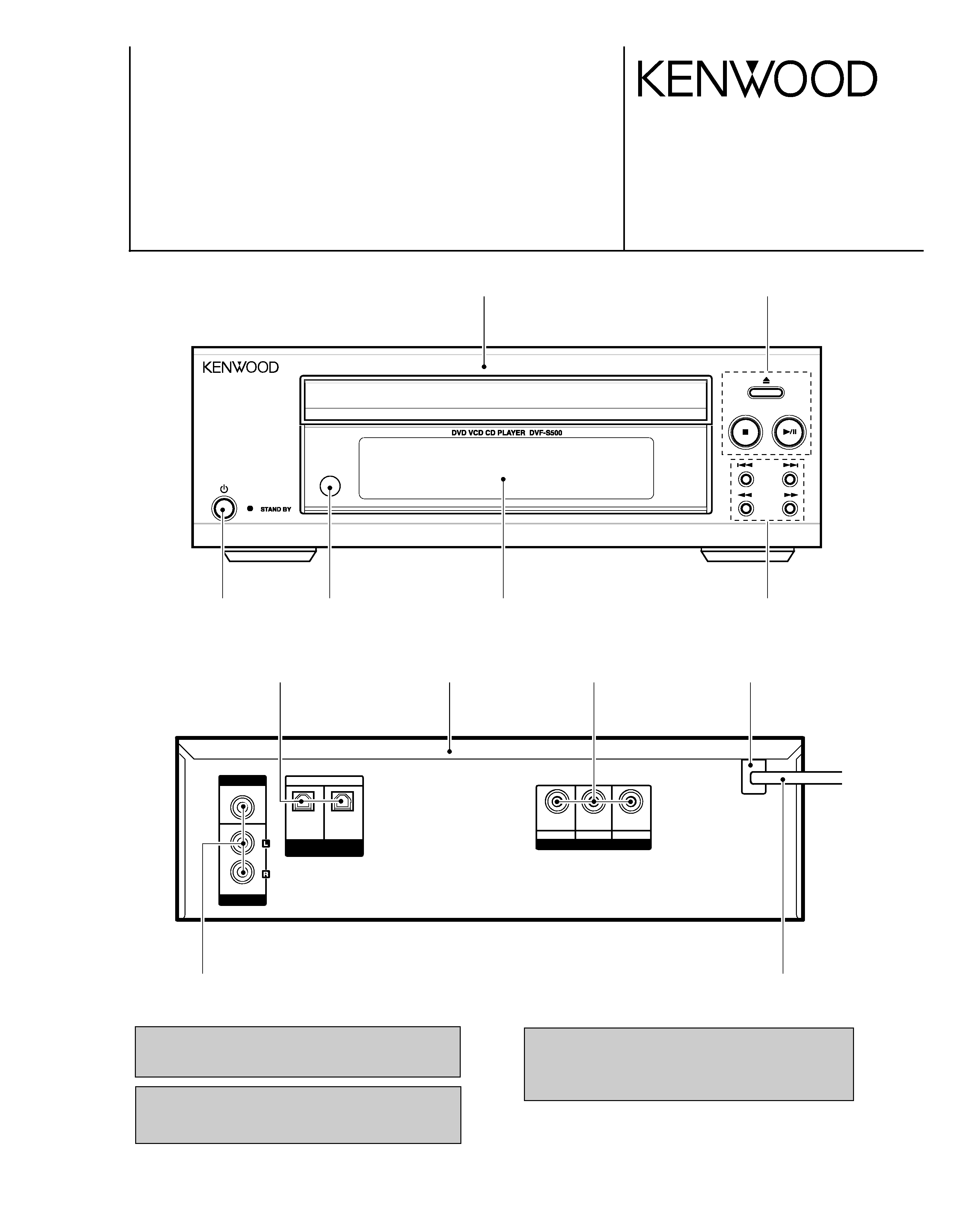
DVD/VCD/CD PLAYER
DVF-S500
SERVICE MANUAL
© 2003-10 B51-5890-00 (K/K) PDF
In compliance with Federal Regulations, following are repro-
duction of labels on, or inside the product relating to laser
product safety.
KENWOOD Corp. certifies this equipment conforms to DHHS
Regulations No.21 CFR 1040. 10, Chapter 1, subchapter J.
DANGER : Laser radiation when open and interlock defeated.
AVOID DIRECT EXPOSURE TO BEAM.
Caution : No connection of ground line if disassemble
the unit. Please connect the ground line on
rear panel, PCBs, Chassis and some others.
COMPONENT VIDEO
OUT
OUT
VIDEO
OPTICAL
AUDIO
DIGITAL OUTPUT
(PCM/BIT STREAM)
1
2
OUT
Y
R
C
B
C
Panel
(A60-2373-08)
Button
(K29-8341-08)
Stopper
(J42-0358-08)
Ter, rca 3pin
(E63-1335-08)
Cabinet
(A01-3919-08)
Module
(W02-4537-08)
Button
(K29-8339-08)
Filter
(B11-1594-08)
Window assy
(B10-3996-08)
Button
(K29-8342-08)
Cord assy
(E30-7309-08)
Ter, rca 3pin
(E63-1336-08)
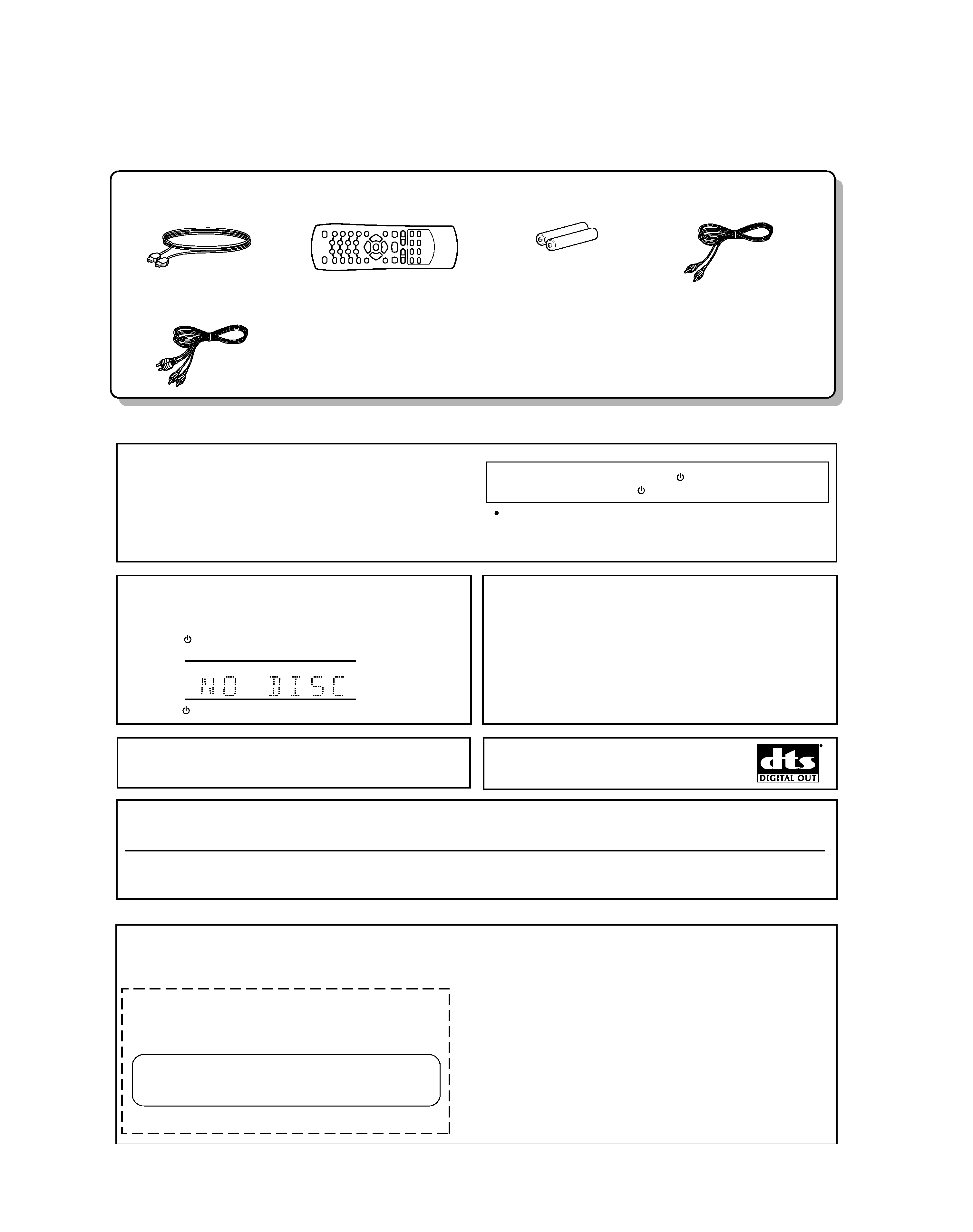
Digital Cable (Optical) ...(1)
(E35-3626-08)
Remote control unit ..........(1)
(A70-1645-08)
Video cord (Yellow) .........(1)
(E30-7311-08)
Audio cord (White / Red) ...(1)
(E30-7310-08)
Batteries (R03/"AAA" -size) ...(2)
DVF-S500
2
ACCESSORIES / CAUTIONS
Accessories
Cautions
"DTS" and "DTS Digital Out" are trademarks of
Digital Theater Systems, Inc.
Manufactured under license from Dolby Laboratories.
"Dolby" and the double-D symbol are trademarks of Dolby
Laboratories.
This product incorporates copyright protection technology that is protected by U.S. patents and other intellectual property rights. Use of this copyright
protection technology must be authorized by Macrovision, and is intended for home and other limited viewing uses only unless otherwise authorized
by Macrovision. Reverse engineering or disassembly is prohibited.
Consumers should note that not all high definition television sets are fully compatible with this product and may cause artifacts to be displayed in the
picture. In case of 525 progressive scan picture problems, it is recommended that the user switch the connection to the "STANDARD DEFINITION"
output. If there are questions regarding our TV set compatibility with this model 525p DVD player, please contact our customer service center.
Caution on condensation
Before transporting or moving this unit, carry out
the following operations.
1. Set the
(POWER) key to the ON without loading a disc.
2. Wait a few seconds and verify that the display shown appears.
3. Set the
(POWER) key to OFF.
Note related to transportation and movement
Condensation (of dew) may occur inside the unit when there is a great differ-
ence in temperature between this unit and the outside. This unit may not fun-
ction properly if condensation occurs. In this case, leave the unit for a few
hours and restart the operation after the condensation has dried up.
Be specially cautious against condensation in the following circumstances:
When this unit is carried from one place to another across a large difference
in temperature, when the humidity in the room where this unit is installed inc-
reases, etc.
CHAP
TRACK
HOUR
MIN
TITLE
Operation to reset
The microprocessor may fall into malfunction (impossibility to operate
erroneous display, etc.) when the power cord is unplugged while
power is ON or due to an external factor.
In this case, switch off the power, wait for several seconds, and then
switch the power on again.
Return to the factory defaults by resetting the microprocessor is done
as shown as follows.
Unplugg the power cord after turn the
(POWER) key OFF.
Then, while holding down the
(POWER) key, plug the power cord.
Please note that resetting the microcomputer will clear the contents
of the memory and returns the unit to the state it was in when it left
the factory.
CAUTION
Use of controls or adjustments or performance of procedures other than those specified herein may result in hazardous radiation exposure.
In compliance with Federal Regulations, the following are reproductions of labels on, or inside the product relating to laser product safety.
KENWOOD CORP. CERTIFIES THIS EQUIPMENT
CONFORMS TO DHHS REGULATIONS NO. 21 CFR
1040.10, CHAPTER 1, SUBCHAPTER J.
Location: Back Panel
KENWOOD CORPORATION
2967-3, ISHIKAWA-CHO,
HACHIOJI-SHI,
TOKYO, JAPAN
For the U.S.A.
3
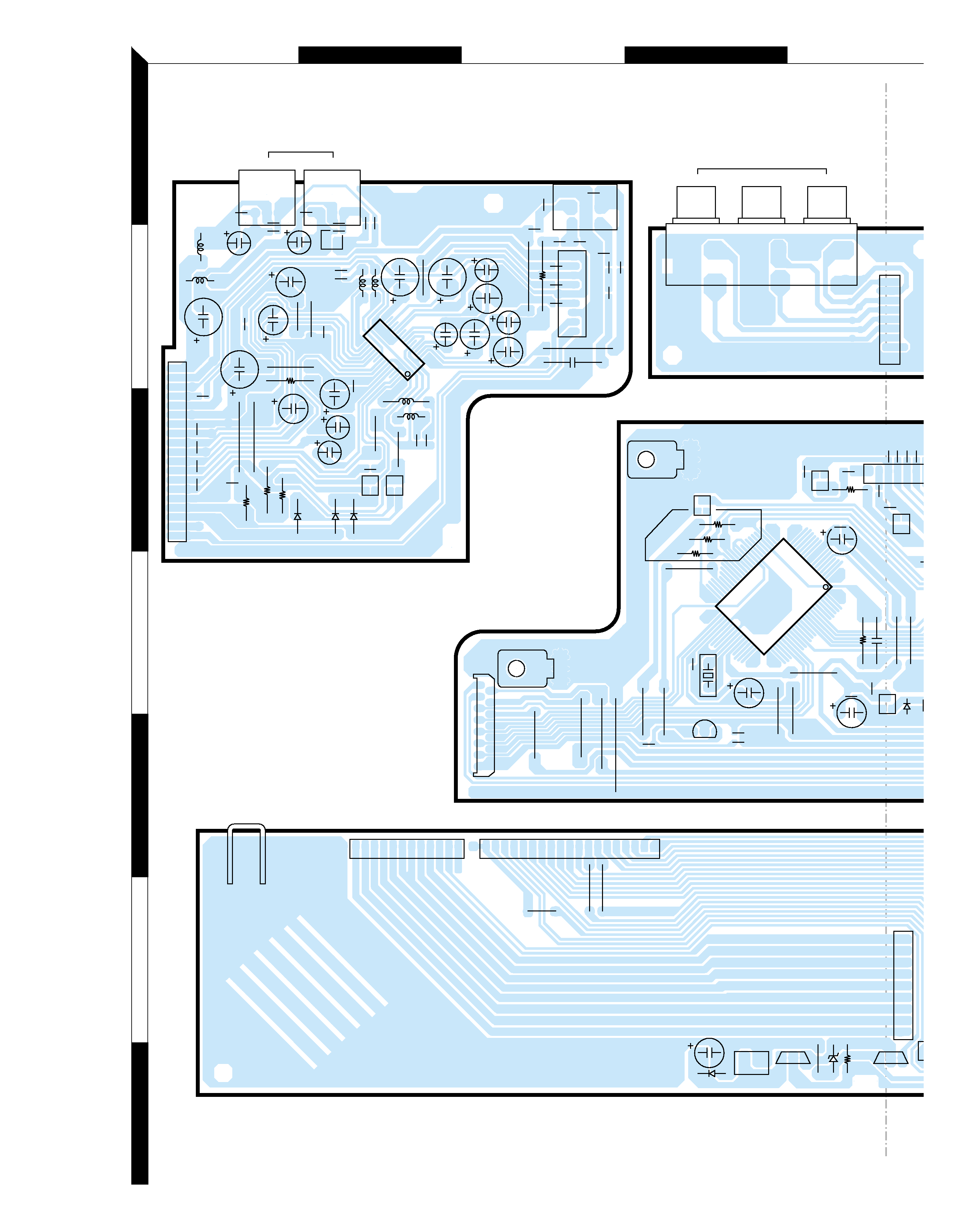
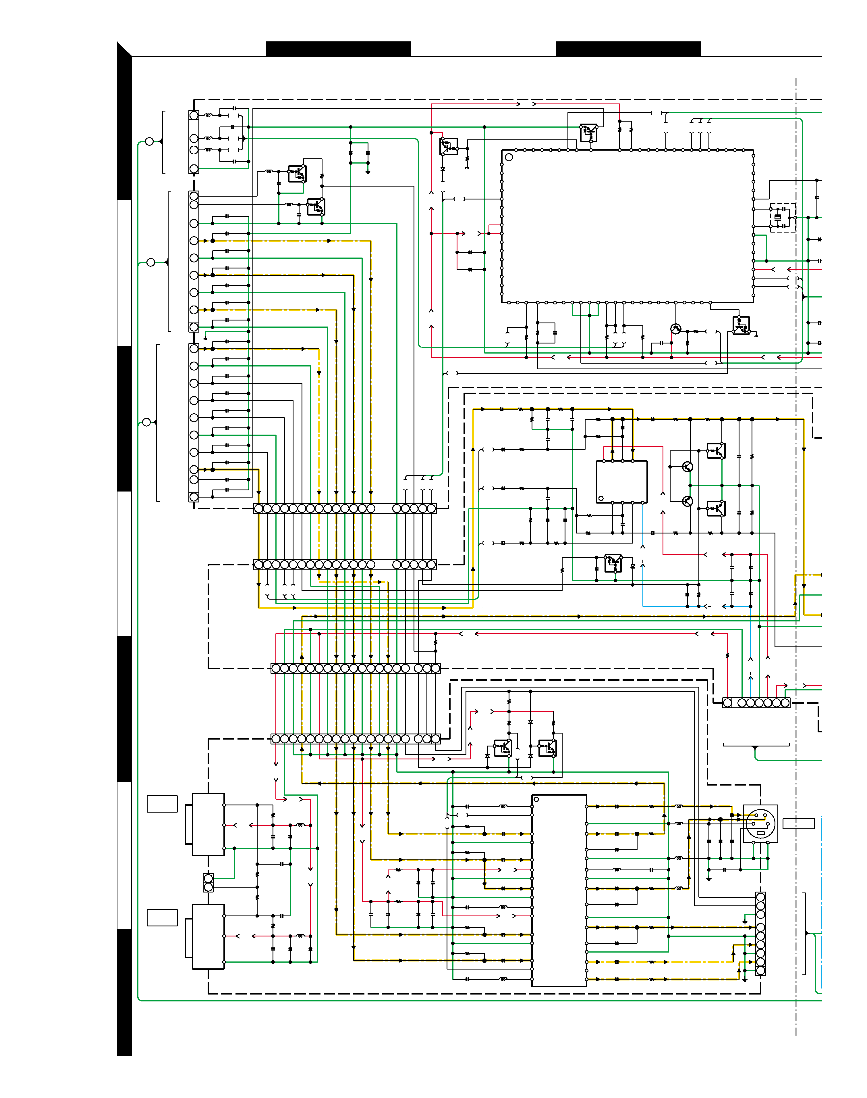
Refer to the schematic diagram for the value of resistors and capacitors.
PC BOARD
AC
E
BD
2
1
3
5
7
4
6
CP601
JACK601
Cr
Cb
OUT
COMPONENT VIDEO
Y
OUT
S-VIDEO
2
1
OPTICAL
DIGITAL OUT
CN201
CP206
CN401
JACK401
CN403
JACK403
JACK402
D401
CP402
D402
D403
Q205
IC201
IC401
IC202
Q206
Q207
Q402
Q403
Q202
Q201
D202
CP304
CP303
CP305
Q307
Q308
D302
CN302
D301
91
10
J222
J208
GND202
L402
C410
J415
R421
J401
C419
C416
C401
C432
C433
C431
C420
C418
C425
L410
C402
C403
C404
C408 C409
C406
C405
C421
C422
L401
C219
XT201
EB
C229
C227
J211
J210
C233
R212
J207
J206
J205
J204
J214
J203
J202
R406
J414
L404
L409
L403
J411
J201
J413
R409
R410
R408
J404
J403
19
1
J418
J410
J409
91
11
11
5
21
4
J209
C231
R201
R204
DVD CONTROL SIGNAL
GND201
R203
R202
J223
GREEN
BLUE
RED
1
9
C441
L405 C429
L407
R420
C436
C435
C434
R419
C437
C414
C417
C430
R401
R402
R403
C428
R417
R418
C415
R422
C413
1
16
17
32
C220
C216
C215
C214
C213
C212
C211
C210
C208
C209
L201
C218
R415
R416
R414
R413
C412
C407
C423
R211
C232
R210
L202
C230
80
1
24
25
40
41
64
65
R213
R215
R209
C228
B
E
GND301
12
1
19
1
J321
J302
C(CVBS)
J303
GND(CVBS)
E
21
B
1
EB
J301
R322
1
9
C324
R324
B
E
B
E
B
E
E
B
E
B
C217
R407
C426
L413
L406
R405
MAIN
VIDEO
COMPONENT
D2
AUDIO
4
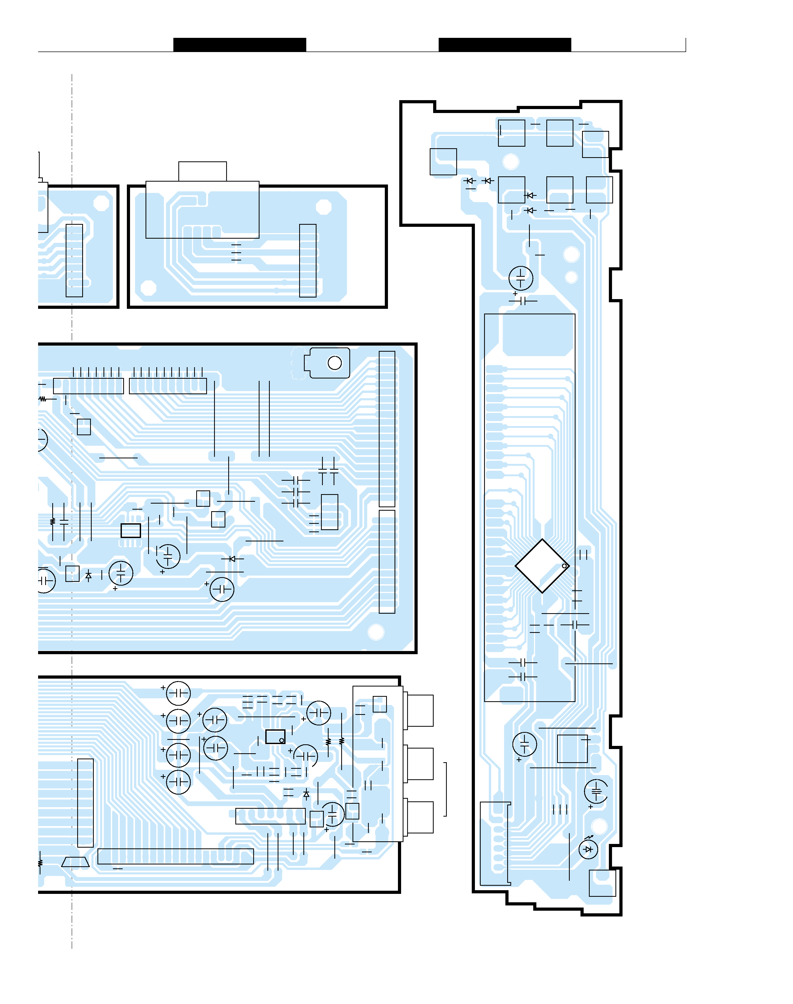
Refer to the schematic diagram for the value of resistors and capacitors.
F
GI
HJ
PC BOARD
CP203
CP204
CP205
D201
CP601
CP501
JACK501
D CONNECTOR
Cr
O
CN201
V.F.D
RMC1
CP101
R
L
VIDEO
OUT
AUDIO
OUT
D101
CN202
S101
S105
S102
S108
S106
S103
S107
S104
IC202
Q204
Q203
Q206
Q202
Q201
D202
7
Q308
CP306
JACK301
CN301
D302
CN302
Q301
Q304
Q302
D304
IC301
IC101
D102 D103
D105
D104
OP/CL
PLAY
STOP
STBY
NEXT
LAST
FF
FR
91
10
1
J222
J212
J208
GND
J101
C112
C102
J102 GND
C101
C103
J103
KEY1
C107
KEY2
J104
RMC J105
C113
C104
34
51
38
J106
GND
15
14
2
1
C229
C235
C227
J217
C225
C224
C226
J216
J215
C234
C221
J218
J213
J211
J210
C233
R212
J209
J220
J219
J221
C222
C231
R201
GND203
1
19
1
12
14
RED
1
9
1
9
L503
L502
L501
C216
C215
C214
C213
C212
C211
C210
C208
C209
C207
C206
C205
C204
C203
C202
C223
C201
L201
C218
L202
C230
80
1
R213
R215
L204
L203
R107
R110
R113
C115
1
11
12
22
23
33
34
44
C110
R106
R108
R109
R112
R111
C111
R105
C108
C106
R114
C114
R103
R102
R101
C105
C116
L205
R209
C228
C236
R214
R206
B
E
B
E
B
E
B
119
71
8
5
1
4
EB
J301
R322
J306
C317
C315
C323
C320
J316
C313
C312
J309
-12V
J310
+12V
C325
C326
C332
J318
J304
J305
J322
J319
J320
J323
R306
R307
YELLOW
WHITE
RED
1
9
C304
R320
R321
R316
R318
R317
C319
C318
C322
C308
R311
R323
C307
R303
C305
L304
L303
C309
R315
R324
R312
R313
R319
C321
C316
C314
C310
C328
C329
C330
C331
L302
L301
R310
C311
R314
R302
B
E
B
E
B
E
E
B
E
B
C217
FRONT
COMPONENT
D2
AC
E
BD
2
1
3
5
7
4
6
CP204
CP304
CP205
CP203
CP303
CP306
CP402
Q203
Q302
Q301
D304
Q304
Q207
Q205
Q
(BOTTOM VIEW)
Q204
CN202
CN201
Q201
Q202
CN301
CN401
JACK401
C
B
A
JACK402
JACK403
CN403
Q402
D403
Q403
D401
CP601
S-VIDEO
OPTICAL 1
OPTICAL 2
DIGITAL
OUT
OUT
DIGITAL
D402
D203
Q305
Q303
(Y) TYPE ON
12 11 10
FL2
FL1
-34V
GND(FL)
12 11 10
C236
0.1
1
2
3
4
DVD I/O
CLK
STB
GND
L203
51
C224 22P
C225
L204
52
C226 22P
L205
62
8
7
6
5
V+
OUT2
IN2-
IN2+
1
2
3
4
OUT1
IN1-
IN1+
V-
47u16
+
C325
R307
560
220P
C322
R320
12K
47u16
+
C320
3.6K
R316
10K
R318
1000P
C319
R317
12K
220P
C318
+
C323
47u16
R321
10K
3.6K
R319
1000P
C321
C305
220P
R303
100K
+
+
+
C312
C313
R313
R315
3.6K
R310
R311
C326
R306
220P
C308
C304
220P
R302
100K
C31
1
R314
C310
C309
R312
47u16
10K
47u16
10K
220P
1000P
12K
1000P
3.6K
12K
560
47u16
C332
+
4.7u50
100u16
C230
0.1
C231
C232
56
0.1
52
51
62
41
100u16
C219
0.1
C220
+
CON2
38
39
1u50
C229
10MHz
XT201
R213
1M
R209
100K
24
+
AUDIO
MUTE
PB7/SO1/DVD
OUT
STBY
LED
44
42
43
45
46
PB5/SCK1/DVD
CLOCK
PB6/SI1/DVD
DA
T
A
IN
47
48
49
50
51
52
PI1/INT1/(POWER
DOEN)
PE0/EC0
PE1/EC1
PE2/RMC
PE3/NMI
53
54
55
56
57
58
PI2/DVD
STB
59
60
61
62
63
64
12
23
22
21
20
19
18
FL
STB
FL
CLK
FL
DIN
20
19
18
17
16
15
14
13
SMPS
CTRL
15
7
6
11
10
9
DVD
RST
F
A
N(LOW)
8
7
3
5
4
2
1
70
65
66
69
68
67
74
73
71
72
77
76
75
80
79
78
PG6/VIDEO MUTE
VDD
NC
AVSS
CON1
KEY2
KEY1
AVREF
VSS
XTAL
EXTAL
RESET(L)
39
38
40
36
37
29
34
33
35
32
30
31
25
27
26
28
4.7K
R204
4.7K
R203
4.7K
R202
10K
R212
10K
R210
0.1
C233
R206
10K
76
8
AUDIO R-
7
C(CVBS)
AMUTE
GND
9
10
8
AUDIO R+
AUDIO L-
6
GND
5
4
AUDIO L+
DVD RST
1
GND
3
2
C209 22P
C208 22P
C207 22P
C203 22P
C206 22P
C205 22P
C204 22P
C223 56P
C202 22P
C201 22P
AUX5
GND
8
7
Y(G)
GND
6
5
Cr(R)
GND
4
3
Cb(B)
GND
2
1
C214 22P
C216 22P
C215 22P
C213 22P
C211 22P
C212 22P
C210 22P
AUX3
9
22P
L201
C217
22P
C218
L202
R201
3.3K
RGB/PROSCAN
GND
GND
1
1
AUX3(WIDE)
32
54
876
10 9
C
GND(MICOM)
P/SCAN
VIDEO
MUTE
32
54
Cr(R)
GND(C)
Y(G)
GND
876
10 9
VIDEO
MUTE
AUDIO
MUTE
17 18 19
15 16
WIDE
GND
14
12 13
Y(G)
Cr(R)
GND
+5V(VIDEO/BUFFER)
13 12 11
15 14
18 17 16
19
VOUT
Cb(B)
GND
GND
13 12 11
15 14
+5V(OPT)
GND(OPT)
GND(VOUT)
18 17 16
19
AUDIO
L+
AMUTE
910 11
78
GND
Cb(B)
GND
C(CVBS)
45
6
23
AUDIO
R+
AUDIO
R-
AUDIO
L-
GND
1
41
8
76
17 18 19
15 16
14
12 13
910 11
78
45
6
23
1
12
3
4
5
6
7
+5V(VIDEO
GND(VIDEO)
-12V
GND(AUDIO)
+12V
+12V(F
AN)
GND(F
AN)
5
4
2
2
5
4
1
2
3
4
5
6
7
8
9
10
11
12
13
14
15
16
CTRAP
MUTE1
CIN
GND
YIN
VCC
GND
PYIN
GND
PYTRAP
VCC
PbIN
GND
PrIN
MUTE2
PrTRAP
32
31
30
29
28
27
26
25
24
23
22
21
20
19
18
17
COUT
TEST
MIXOUT
MIXFB
GND
YTRAP
GND
YOUT
YFB
GND
PYOUT
PYFB
GND
PbOUT
N.C.
PrOUT
R413 100
C423 0.1
C422 1u50
+
R414 82
C421 1u50
+
C420 47u16
R415 100
+
C419 47u16
R416 100
+
C412 47P
L402 0.68uH
L403 0.39uH
C414 22P
C417 47P
L404 0.68uH
R405 75
C410 0.1
R407 75
C409 100u16
+
C408 22u16
+
L401 0.68uH
C407 47P
+
C406 100u16
C405 22u16
+
R406 75
C404 100u16
C403 22u16
+
+
R403 75
+
C402 330u10
R402 75
+
C401 330u10
R401 75
C316
0.1
100u16
C317
+
C314
C315
100u16
0.1
+
/BUFFER)
R422
C418
C415
0.1
+
100u16
27
R421
27
C416
100u16
C413
0.1
+
C426
0.1
C425
330u10
+
9
8
7
6
5
4
3
2
1
WIDE(LINE3)
P/SCAN
GND
CY
GND(CY)
Cb
GND(Cb)
Cr
GND(Cr)
L406
L405
L407
C428
22P
C429
22P
C430
22P
L413
C441 22P
6
5
1
3
4
2
OUT
+5V
GND
C433
0.1
C434
22u16
+
100uH
L409
4.7K
R419
22P
C437
75
R417
C436
+5V
R418
75
GND
OUT
C432
22P
0.1
C435
22u16
+
L410
100uH
4.7K
R420
330u10
+
C431
1
2
S/PDIF
GND
4.7K
R409
R410
4.7K
3.3K
R408
2
15
15
2
9
8
7
6
5
4
3
2
1
GND
CY
GND(CY)
Cb
GND(Cb)
Cr
GND(Cr)
4.7K
0.01
C222
0.1
C221
41
+12V
+12V
+12V
12V
12V
12V
+12V
+5V
+5V
+5V
+5V
+5V
+5V
+5V
+5V
+5V
34V
+5V
+5V
+5V
+5V
+5V
+5V
+5V
+5V
+5V
+5V
+5V
+5V
22P
4.7K
R215
4.7K
R214
+5V
45
R211
300
10K
R323
0.1
C307
R324
34V
C234
100u16
+
0.1F6.3
+
C237
R308
560
560
R309
300
R325
1
R326
1W
+
MAIN
AUDIO
VIDEO
IC301
IC201
IC401
C
5
MAIN (1/3)
DVF-S500