70%
In compliance with Federal Regulations, following are repro-
duction of labels on, or inside the porduct relating to laser
product safety.
KENWOOD-Crop. certifies this equipment conforms to DHHS
Regulations No.21 CFR 1040. 10, Chapter 1, subchapter J.
DANGER : Laser radiation when open and interlock
defeated.
AVOID DIRECT EXPOSURE TO BEAM.
Caution : No connection of ground line if disassemble
the unit. Please connect the ground line on
rear panel, PCBs, Chassis and some others.
DVD VCD CD PLAYER
DV-4050-B
DVF-R6030-B
SERVICE MANUAL
© 2000-9/B51-5661-00 (K/K) 1399
STANDBY
ON/STANDBY
STANDBY
ON/STANDBY
POWER
DISC
5
changer
DISC SKIP
DISC
1
DISC
2
DISC
3
DISC
4
DISC
5
OPEN/CLOSE
0
3
8
7
VIRTUAL
SURROUND
4¢
COAXIAL OPTICAL
DIGITAL OUTPUT
(PCM/BIT STREAM)
OUTPUT
COMPONENT VIDEO OUTPUT
SUB WOOFER
Y
Cb
Cr
S VIDEO
L
1
2
R
2
OUTPUT
LINE OUTPUT
VIDEO
1
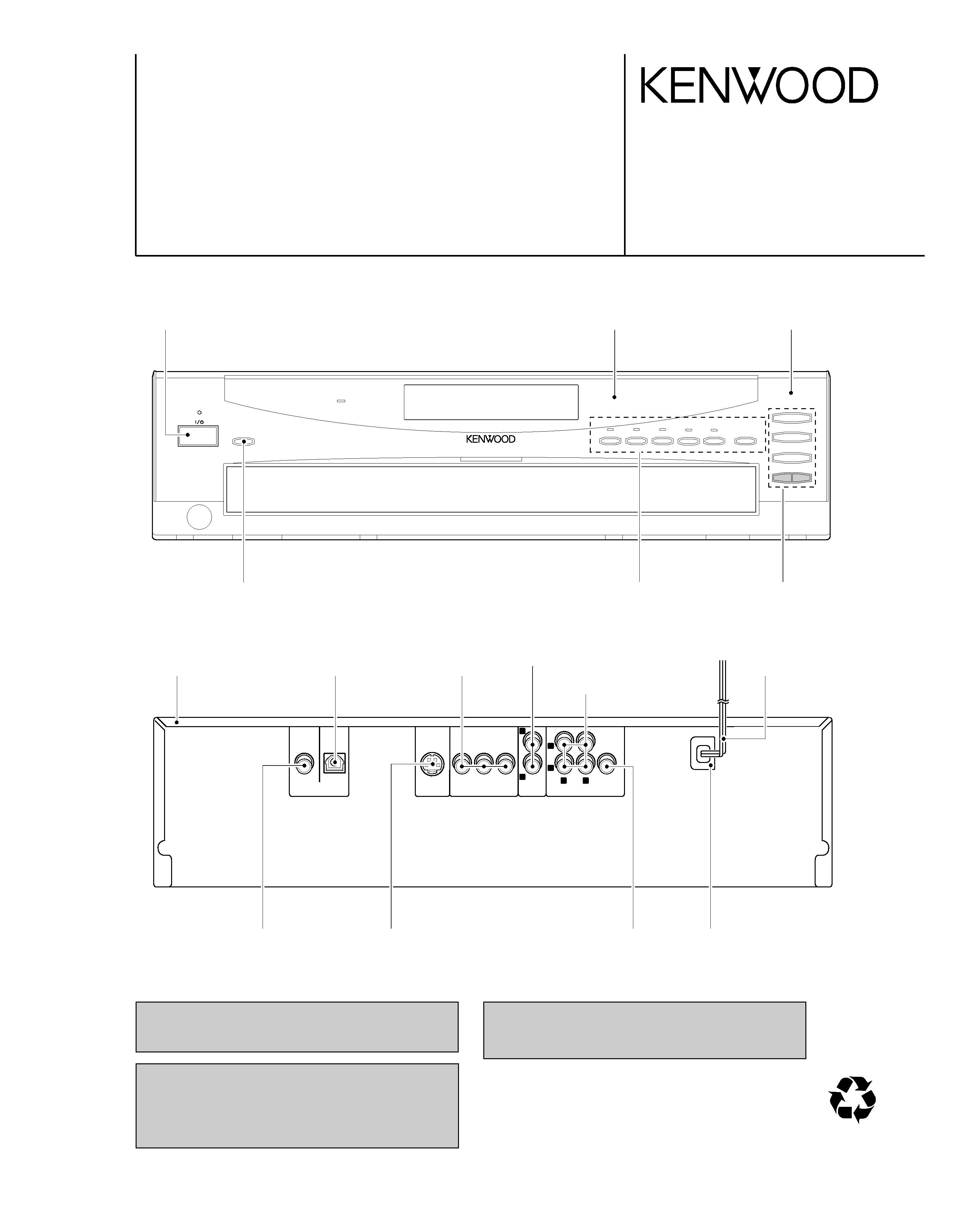
Knob
(K29-7823-13)
Knob
(K29-7804-13)
Knob
(K29-7801-13)
Metallic cabinet
(A01-3776-01)
Pin jack
(E63-1159-05)
Pin jack
(E63-1127-05)
Oscillating module
(W02-2732-05)
Front glass
(B10-3610-02)
Panel *
(A60-)
Pin jack
(E63-1162-05)
AC power cord bushing
(J42-0083-05)
AC power cord *
(E30-)
Pin jack
(E63-1161-05)
Cylindrical receptacle
(E56-0032-05)
Knob
(K29-7822-13)
* Refer to parts list on page17.
Pin jack
(E63-1157-05)
DV-4050-B/DVF-R6030-B
2
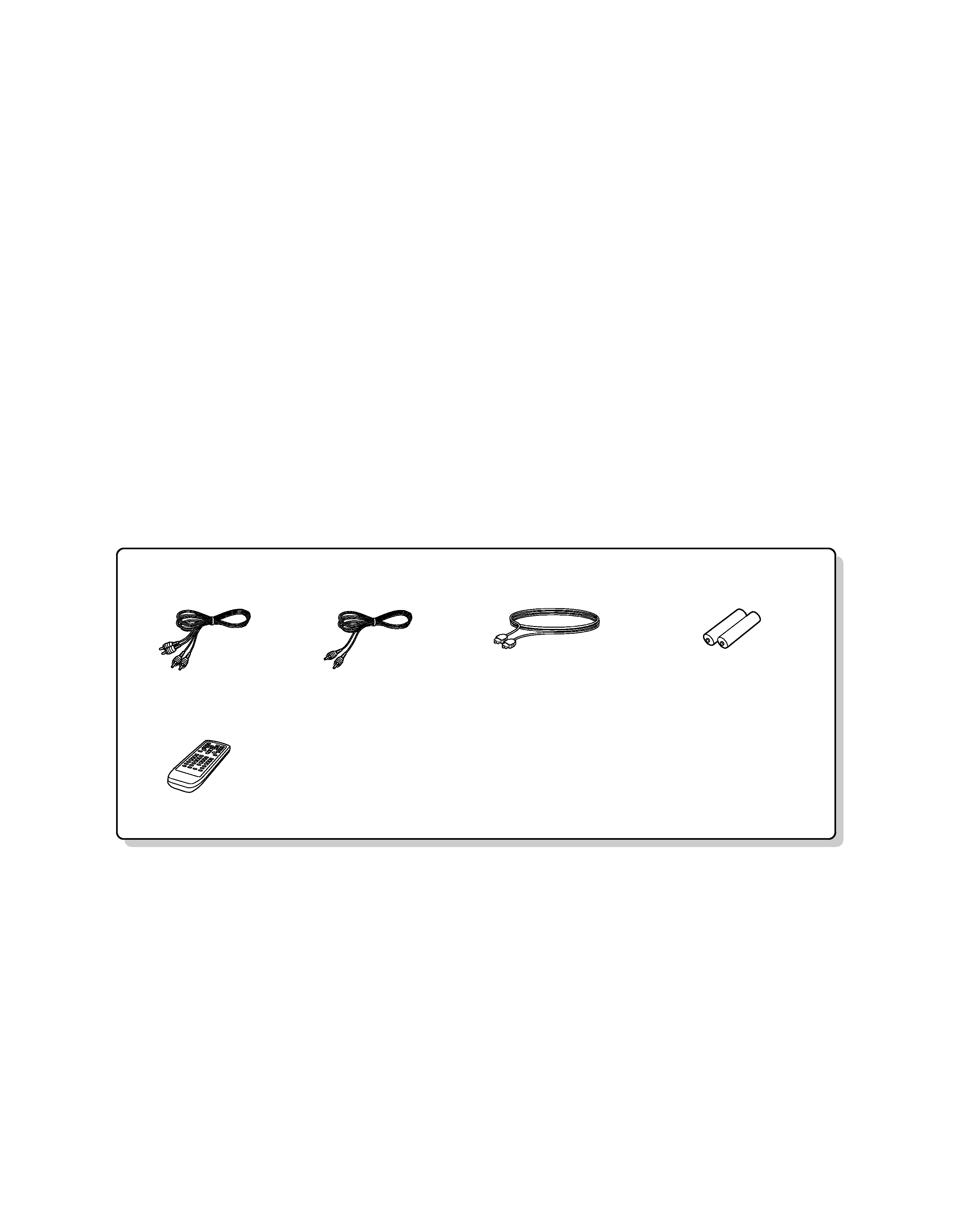
CONTENTS / ACCESSORIES
CONTENTS / ACCESSORIES .................................. 2
DISASSEMBLY FOR REPAIR....................................3
ADJUSTMENT ............................................................5
PC BOARD..................................................................7
.
SCHEMATIC DIAGRAM ............................................ 9
EXPLODED VIEW ....................................................15
PARTS LIST..............................................................17
SPECIFICATIONS ....................................................20
Contents
Accessories
Remote control (1)
(A70-1420-05)
Battery cover(A09-1213-08)
Batteries (2)
for remote control
Audio cable (1)
(E30-0505-05)
Video cable (1)
(E30-1427-05)
Optical digital audio cable (1)
(B19-1529-05)
Note: Please contact our KENWOOD Service Department in your side if you want the information;
Microprocessor(MN101C35D) ports explanation and full (previous) format parts list on this
model. You can be available them by internet from us.
Note: Test Mode in detail is written in
DV-4900/DV-4700/DVF-R6030/DVF-R9030 Service Manual(B51-5665-00).
DV-4050-B/DVF-R6030-B
3
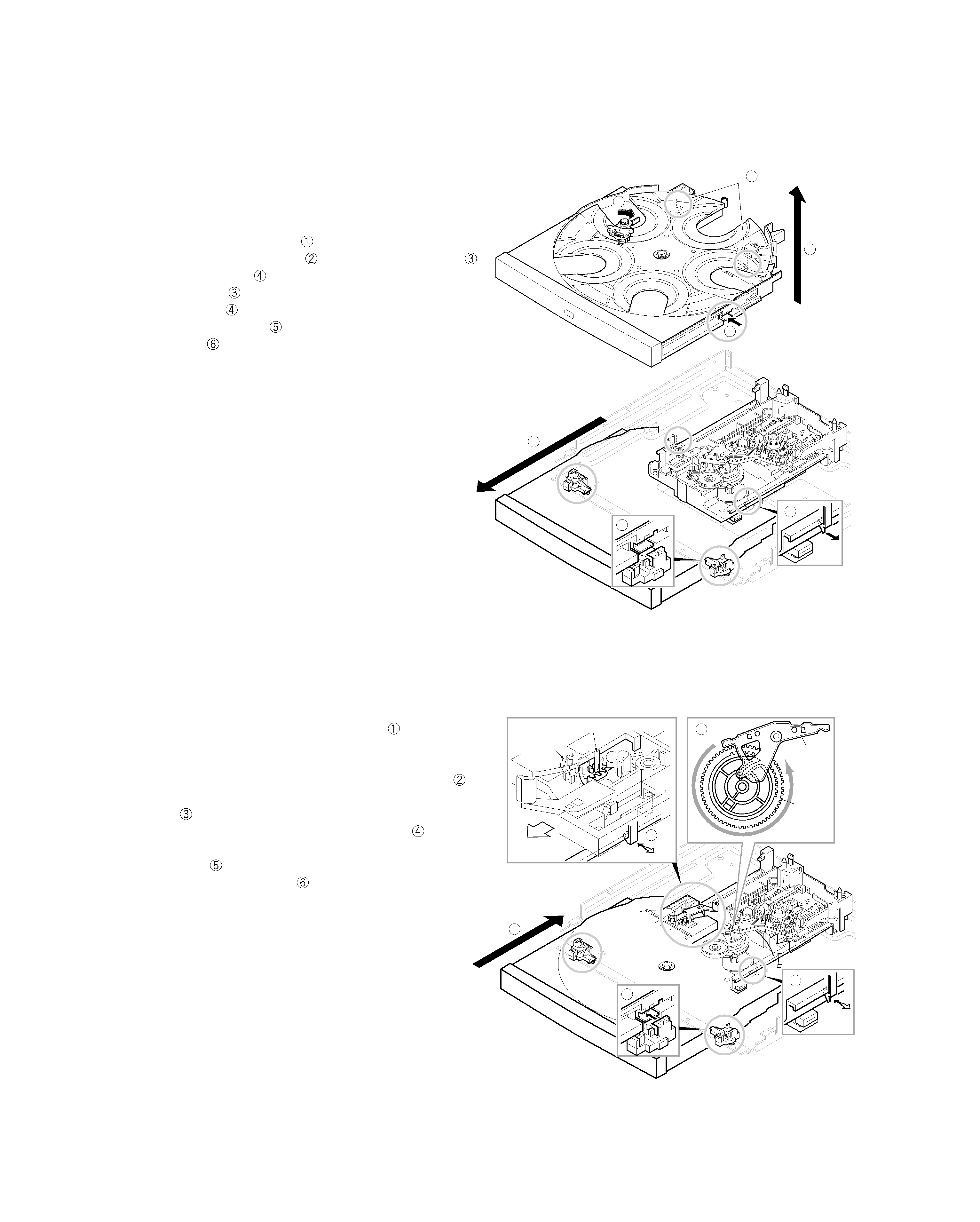
DISASSEMBLY FOR REPAIR
1
5
2
3
6
4
5
HOOK (
x2)
HOOK
x2
Guide
6
3
4
HOOK
GUIDE
ARM
DRIVE
GEAR
HOOK
LOADING
GEAR (A)
(Free)
PROTRUSION OF TRAY
2
1
5
REAR
1. How to Remove Tray
1. Remove the front panel and flexible cable.
Disassemble the X25 and power supply pcb with sub
chassis if it is a difficult.
2. Push and hold the lever(
)to clockwise and pull barely
out the tray to frontwards(
) where the hook of tray(
)
meets with guide(
).
3. Push hooks(
), both sides, inwards and release them
from guides(
).
4. Pull hooks of tray(
) outwards and remove the tray
upwards(
).
2. How to Assemble Tray
1. Adjust the position of drive gear as figure(
).
Check traverse unit is at the lowest position.
2. Load the tray on the loading mechanism.
Check the position where the loading gear(A) is free(
)
3. Meet the hooks with guides and push hooks to load the
tray(
).
4. Set the right side hook to loading mechanism(
).
5. Set the left side hook to loading mechanism with pulling it
outwards(
).
6. Push the tray backwards(
).
DV-4050-B/DVF-R6030-B
4
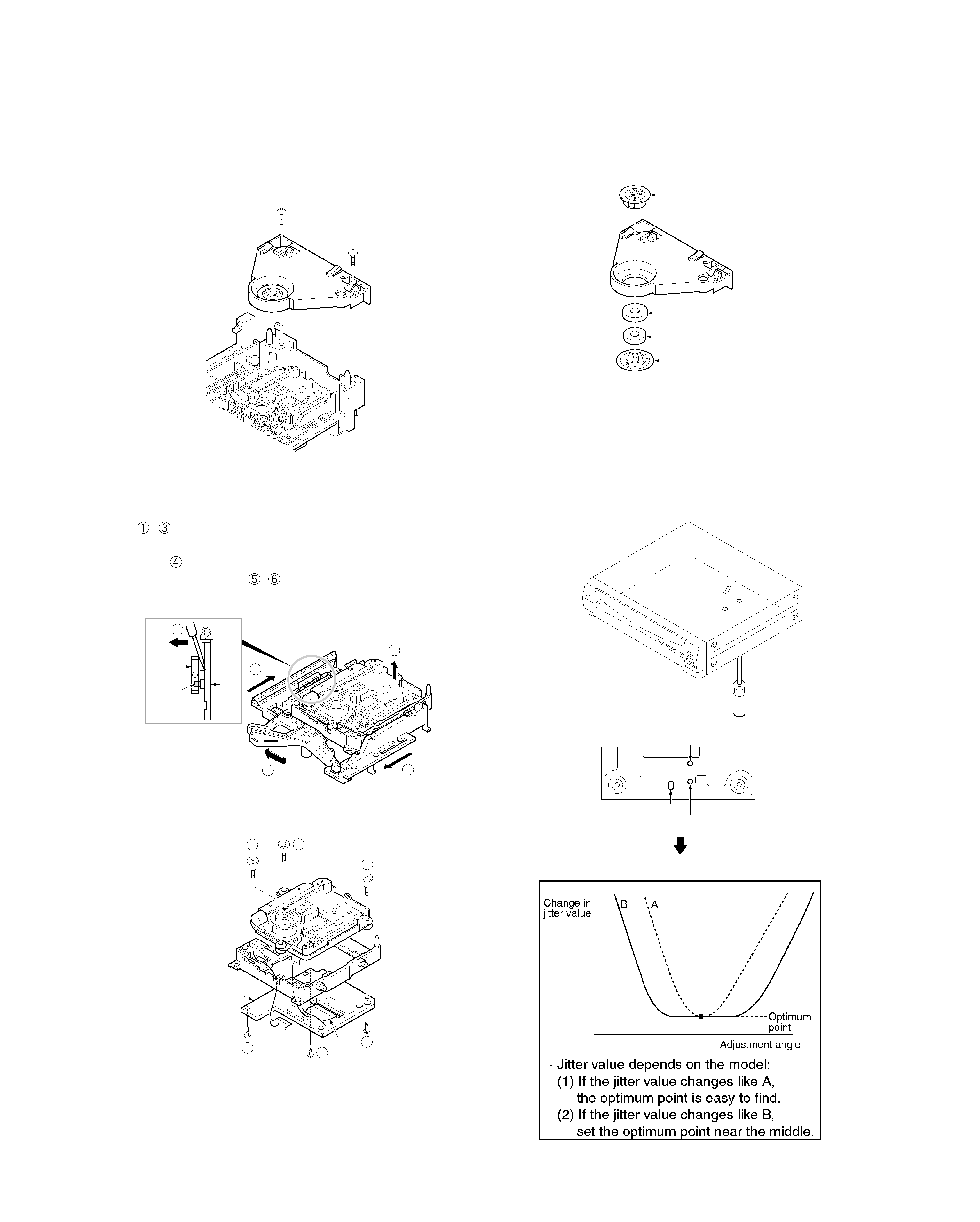
DISASSEMBLY FOR REPAIR
5. How to Disassemble Traverse Unit
1. Move the traverse to upward by turning motor pulley
(
~
).
2. Make the gap between the tray guide and guider(L) with
driver(
)
3. Remove the screws(
,
).
6. Tangential and Tilt Adjustment
1. Turn the power on with pressing the DISC 1 key.
(Display shows "INSPECTION"; test mode.)
2. Press the DISC1 key in playback mode again.
Display shows "Jitter *** %"
3. Turn off if cancel test mode.
2
4
2
1
3
Tray
guide
Guider
(L)
Protruding
part
5
5
5
6
6
6
X13-7770-10
CN1
CN2
Clamper weight
Spacer
Magnet
Clamper
3. How to Remove Clamper Ass'y
1. Remove screws.
4. How to Disassemble Clamper Ass'y
REAR
Tilt adjustment screw 2
Tilt adjustment screw 1
Tangential adjustment screw
DV-4050-B/DVF-R6030-B
5
CIRCUIT DESCRIPTION
Pin No.
Pin Name
I/O
Description
1
CMD
O
Serial output for system communication.
2
STATUS
I
Serial input for system communication.
3
DSPCLK
I
Serial clock for system communication.
4
DATA
O
Data signal output to buffer.
5
STB
O
Strobe signal output to buffer.
6
CLK
O
Clock signal output to buffer.
7
CLR
O
Clear signal output to buffer.
8
VDD
-
+5.0V power supply.
9
OSC2
O
Main clock (8MHz) output.
10
OSC1
I
Main clock (8MHz) input.
11
VSS
-
Connected to ground.
12
XI
-
Connected to ground.
13
XO
-
Unused.
14
MMOD
-
Connected to ground.
15
VREF-
-
Connected to ground.
16~18
KEYIN0~2
I
Key signal input.
19,20
PA3,PA4
-
Unused.
21
CLOSE SW
I
Disc clamp control.
22
OPEN SW
I
Control port of tray open/close for changer mechanism.
23
PA7
-
Unused.
24
VREF+
-
A/D reference voltage.
25
TM+
O
Control port of tray motor.
26
RESET
I
Reset signal input.
27
RM+
O
Control port of tray motor.
28
TRM-
O
Control port of tray motor.
29
MECHA VR
O
Control port of tray motor.
30
POWER
O
Control port of power supply.
31
POWER MUTE
O
Power on/off control.
32
P15
-
Unused.
33
REMOCON
I
Input port of remote control signal.
34,35
P21,P22
-
Unused.
36
POSITION
I
Detection port of tray position.
37
SPEED
I
Detection port of rotation speed for tray.
38~
P25,P30~P32
-
Unused.
42
STBY-LED
O
Control port of standby LED.
43
P51
-
Unused.
44
VSS-LED
O
Control port of VSS LED.
45,46
DESTINATION IN
I
Unused.
47~49
DESTINATION OUT
O
Unused.
50
DIGI 4
-
Unused.
51~63
1G~13G
O
FL grid output.
64~80
P17~P1
O
FL segment output.
81~98
SEG24~SEG41
-
Unused.
99
SW MUTE
O
Control port of sub woofer.
100
VFL
-
FL power supply.
Microprocessor pin description : MN101C35D(X14,IC1)