DVD VCD CD PLAYER
DV-303/DVF-5020/K5020
SERVICE MANUAL
REVISED
© 1999-10/B51-5583-00 (K/K) 1836
70%
In compliance with Federal Regulations, following are repro-
ductions of labels on, or inside the product relating to laser
product safety.
KENWOOD-Crop. certifies this equipment conforms to DHHS
Regulations No. 21 DFR 1040. 10, Chapter 1, Subchapter J.
DANGER : Laser radiation when open and interlock
defeated.
AVOID DIRECT EXPOSURE TO BEAM
Caution : No connection of ground line if disassemble
the unit. Please connect the ground line on
rear panel, PCBs, Chassis and some others.
NOTE : Please use the remote controller
for self-diagnosis and tilt adjust-
ment.
STANDBY
VIRTUAL
SURROUND
OPEN/CLOSE
DIGITAL OUTPUT
(PCM/BIT STREAM)
OPTICAL COAXIAL
AUDIO OUTPUT
VIDEO OUTPUT
VIDEO OUTPUT
SELECTION
COMPONENT
VIDEO OUTPUT
Cr
Cb
Y
S-VIDEO
AC IN~
L
R
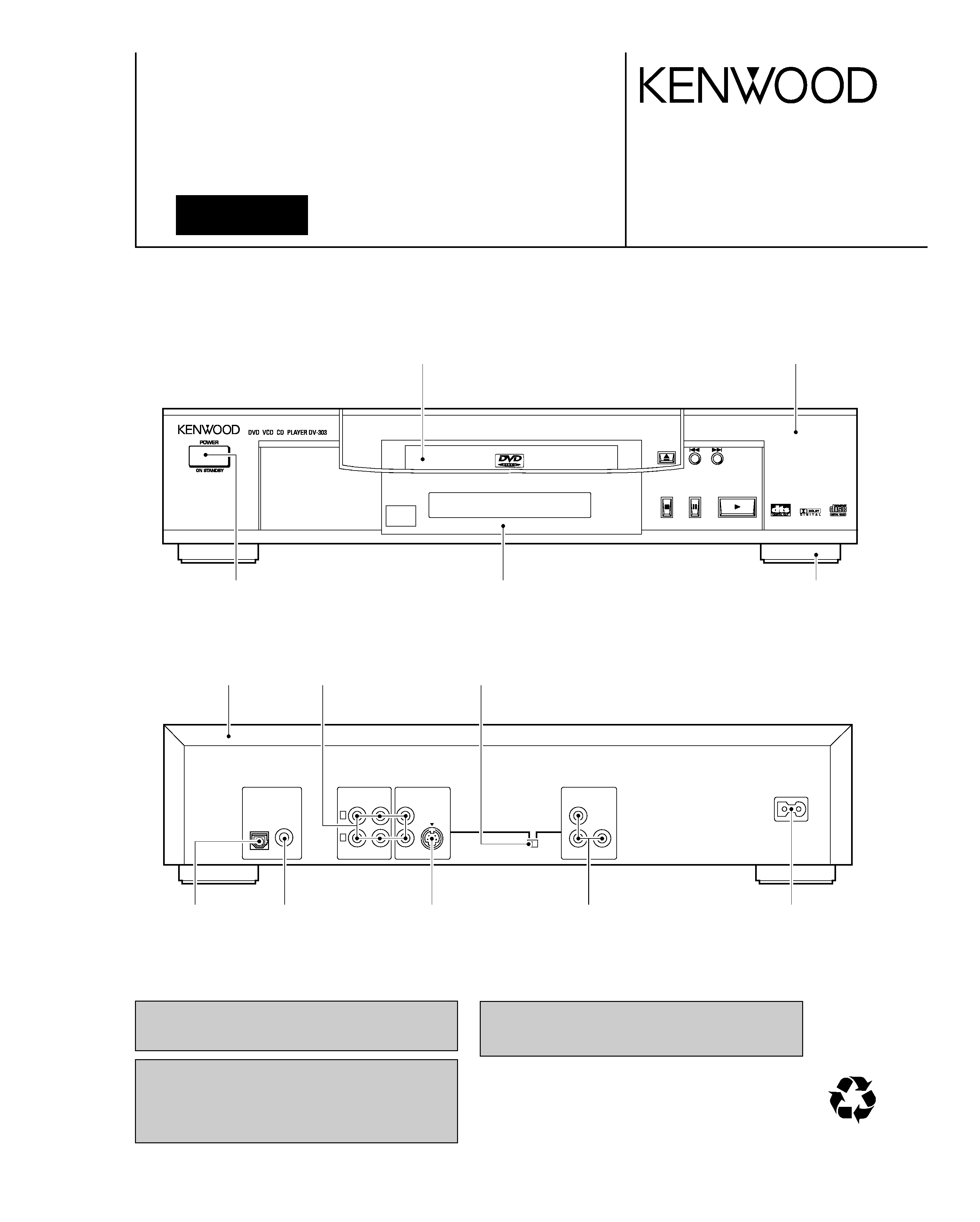
Front panel
(A60-1788-08)
Tray top
(A29-1088-08)
Top cover
(A01-3749-08)
Leg
(J02-1468-08)
Pin jack
(E63-1135-08)
Oscillating module
(W02-2736-08)
Y/C connector
(E40-8534-08)
RCA jack
(E63-1134-08)
Front cover
(B10-3573-08)
Power button
(K27-2389-08)
Switch
(S90-0134-08)
Connector
(E40-8535-08)
Pin jack
(E63-1133-08)
Figure is DV-303.
Please use this manual instead of DV-303's manual (B51-5561-00), when repair of DV-303.
DV-303/DVF-5020(k)COVER1,1P( 99.11.210:39AM y[W 1
DV-303/DVF-5020/K5020
2
CONTENTS / ACCESSORIES
CONTENTS / ACCESSORIES .................................. 2
DISASSEMBLY FOR REPAIR....................................3
BLOCK DIAGRAM ....................................................13
CIRCUIT DESCRIPTION ..........................................17
ADJUSTMENT ..........................................................21
ABBREVIATION........................................................22
VOLTAGE CHART....................................................24
WIRING DIAGRAM ...................................................30
PC BOARD .............................................................. 32
SCHEMATIC DIAGRAM .......................................... 41
EXPLODED VIEW ....................................................93
PARTS LIST..............................................................96
SPECIFICATIONS ......................................Back cover
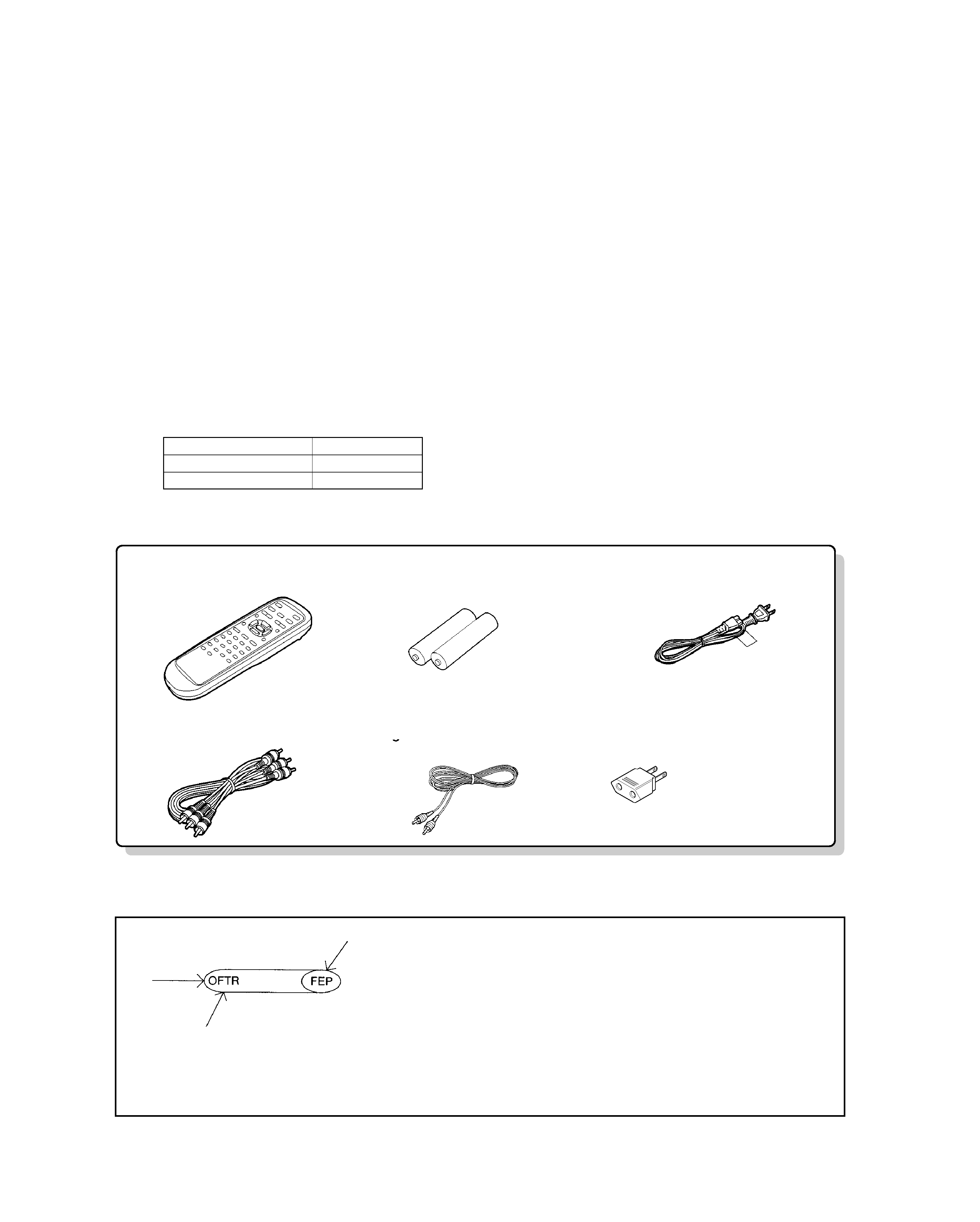
Contents
(A70-1353-08): K,K1,Y
(A70-1369-08): M
(E30-2937-08): K,K1
(E30-2946-08): Y,M
(E30-2938-08)
(E30-2365-05)
Remote control unit . . . . . . . . . 1
for remote control unit [size "AA"]
Batteries. . . . . . . . . . . . . . . . . . . . 2
AC cord. . . . . . . . . . . . . . . . . . . .. . 1
Video/audio cable. . . . . . . . . . . . 1
Digital cord. . . . . . . . . . . . . . . . . . . 1
(E03-0115-05): M
Ac plug adapter. . . . . . . . . . . . . . . 1
Use to adapt the plug
on the power cord to
the shape of the wall outlet.
(Accessory only for regions where use is
necesary.)
Accessories
Note: There is different part in this manual as compared with a usual one because we use OEM
factory's data.
"Disassembly for repair" is for DV-303.
KENWOOD MODEL
OEM MODEL
DV-303,DVF-5020
DVD-A120U
DVF-K5020
DVD-A160EN
How to read the schematic diagram
· There are some destinations in this schematic.
· Figures which is more than 20,000 is omitted first digit in Mic jack and Mic volume circuit.
(Example) R4001 î R24001
Connection of "from" or "to".
Port name
DV-303/DVF-5020(k)COVER1,1P( 99.11.210:39AM y[W 2
DV-303/DVF-5020/K5020
3
DISASSEMBLY FOR REPAIR
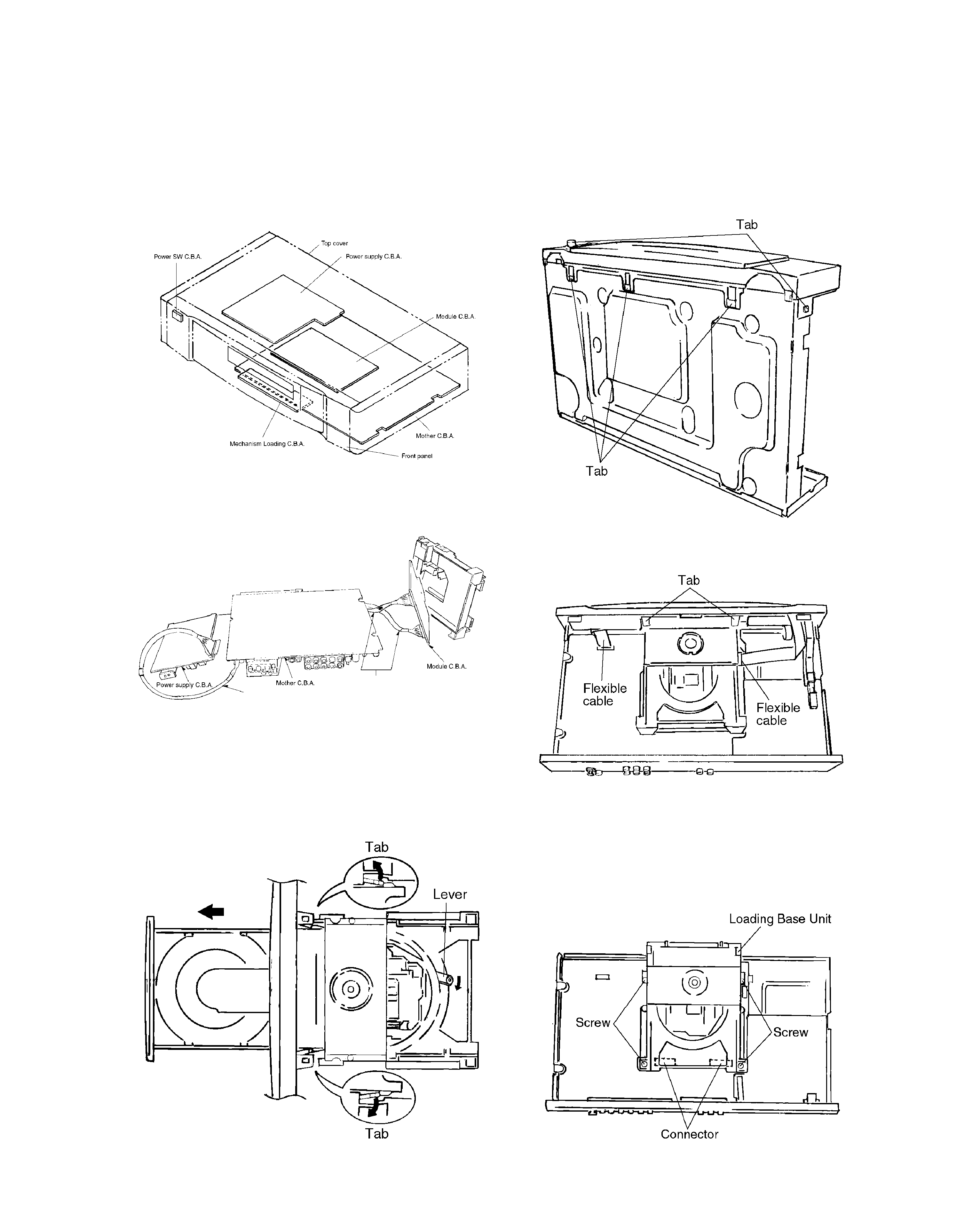
1-1 Casing Parts and C.B.A. Positions
1. Assembling and Disassembling the Casing
and Checking C.B.A.s (DV-303)
1-4 Disassembling the Front Panel
1. Release the 3 tabs on the bottom.
2. Release the 2 tabs on the left and right.
3. Release the 2 tabs.
4. Disconnect the 2 flexible cables.
1-5 Disassembling the Loading Base Unit
1. Remove the 4 screws.
2. Pull out the loading base unit vertically.
Note
There is a danger of damaging the connectors.
1-2 Service Positions
Note
To inspect the loading base unit, position the left side
upward (as viewed from the front).
1-3 Disassembling the Tray
1. Turn the lever clockwise.
2. Move the tray in the direction of the arrow until it locks.
3. Release the tab locks on the left and right, then pull out
the tray.
Extension cable (A)
Extension cable (B)x2
DV-303/DVF-5020(k)COVER1,1P( 99.11.210:39AM y[W 3
DV-303/DVF-5020/K5020
4
DISASSEMBLY FOR REPAIR
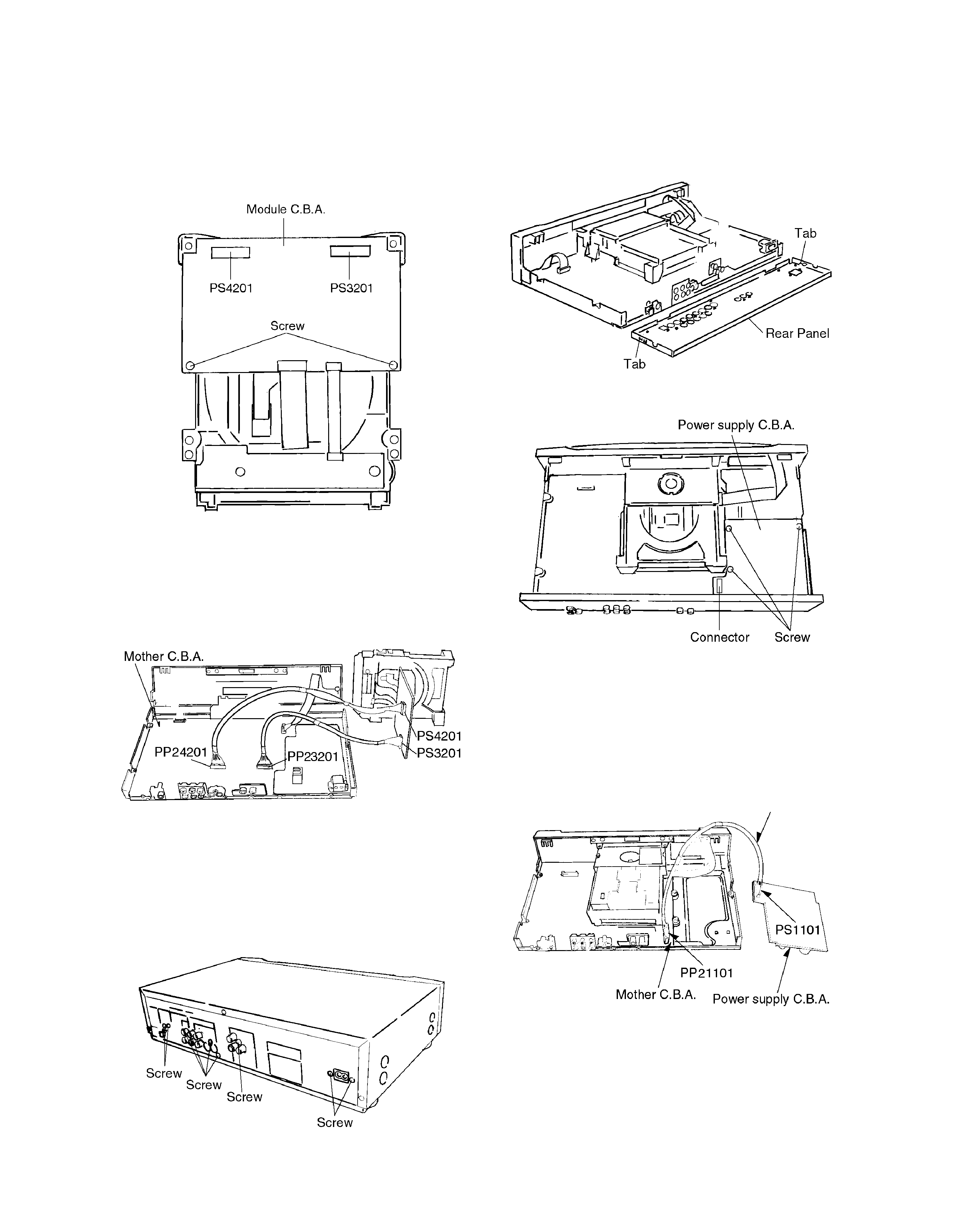
1-6 Checking the Module C.B.A.
1. Remove the 2 screws.
2. Connect the module C.B.A. to the mother C.B.A. with the
extension cables for inspection.
· Extension cable (B)x2
Mother C.B.A. Module C.B.A.
PP24201-PS4201
PP23201-PS3201
Note
Be sure to initialize the player whenever you replace a
C.B.A. (Refer to page21/4-1 Initializing the DVD Player.)
1-7 Disassembling the Rear Panel,
1. Remove all of the screws connected to the rear panel.
(The number of screws varies according to the model).
1-8 Checking the Power Supply C.B.A.
1. Remove the 3 screws.
2. Carefully pull out the power supply C.B.A.
Note
There is a danger of damaging the connectors.
3. Connect the power supply C.B.A. and the mother C.B.A.
with the extension cable for inspection.
· Extension cable(A) (connects the power supply C.B.A.
PS1101 and the mother C.B.A. PP21101)
2. Release the two tabs on the left and right.
Extension cable(A)
DV-303/DVF-5020(k)COVER1,1P( 99.11.210:39AM y[W 4
DV-303/DVF-5020/K5020
5
DISASSEMBLY FOR REPAIR
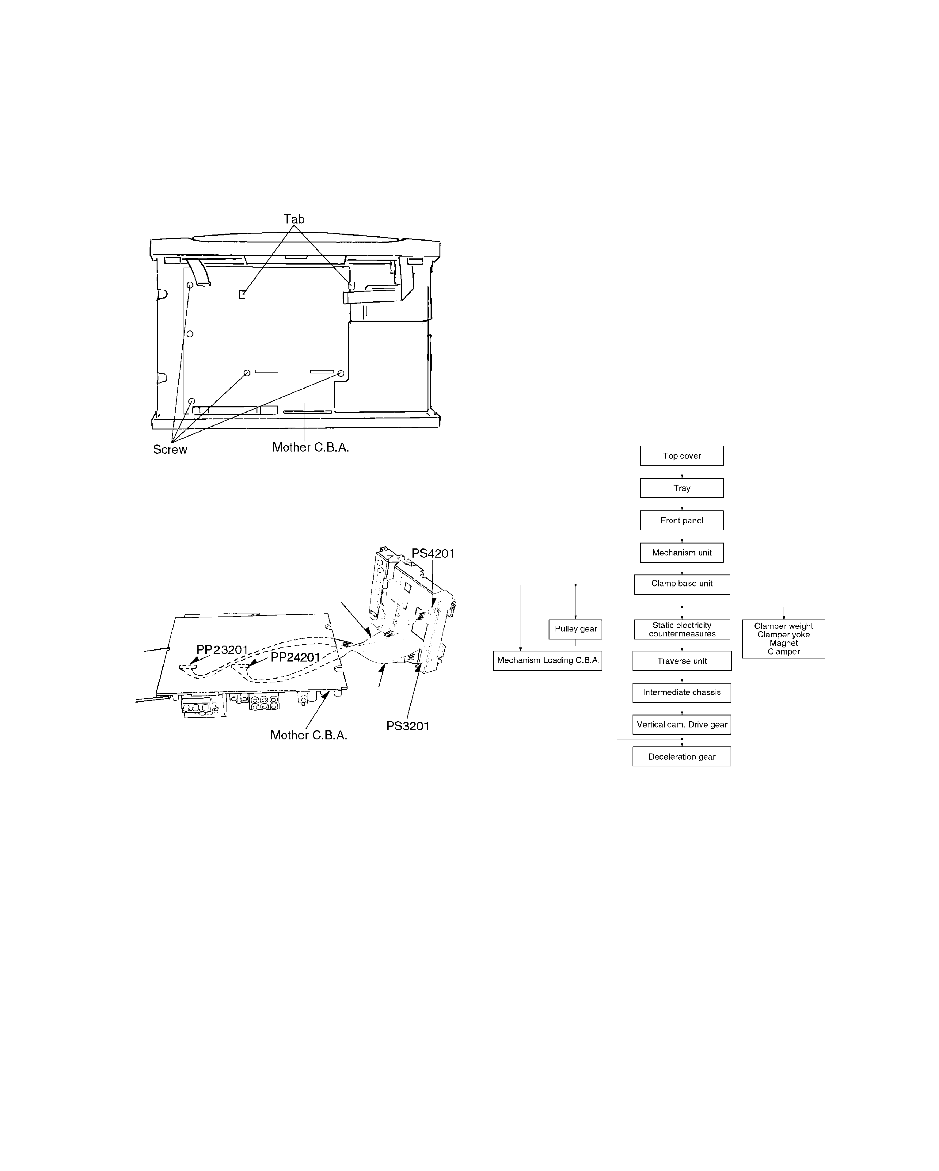
1-9 Checking the Mother C.B.A.
1. Remove the 5 screws.
2. Release the 2 tabs.
2. To preserve the quality of the optical pickup replacement
parts during transport and installation, the terminals of
the laser diode are short-circuited. After replacing the
parts, use the proper procedure to return the laser diode
to its original condition. (Refer to page9/2-12 Assembling
the Optical Pickup.)
3. Testers cannot be used to check the laser diode of the
optical pickup. The power supply inside the tester can
easily damage the laser diode.
4. Take care when handling the flexible cable because
excessive force can cause it to break.
5. You cannot adjust the semifixed resistor for laser power
adjustment. Do not turn it.
2-2 Disassembly Procedure
Use the following procedure to replace major parts.
For the assembly procedure, follow the flow chart in reverse.
3. Checked by connecting the module C.B.A. and the moth-
er C.B.A. with the extension cables.
Extension cable (B)x2
Module C.B.A. Mother C.B.A.
PS3201-PP23201
PS4201-PP24201
Note
Be sure to initialize the player whenever you replace a
C.B.A. (Refer to page21/4-1, Initializing the DVD player.)
2. Assembling and Disassembling the Optical
Pickup (Mechanical Parts)
The optical pickup can be damaged by static electricity from
your body. Be sure to take static electricity countermeasures
when working around the optical pickup.
2-1 Handling the Optical Pickup
The optical pickup can be damaged by static electricity
from your body. Be sure to take static electricity counter-
measures when working around the optical pickup.
1. The optical pickup is an extremely high-precision mecha-
nism. Do not subject it to strong impact.
Extension cable(B)
Extension
cable(B)
DV-303/DVF-5020(k)COVER1,1P( 99.11.210:40AM y[W 5