© 2002-5 PRINTED IN JAPAN
B51-7955-00 (N) 1739
CD CASSETTE DSP RECEIVER
DPX-3030/MP4030
SERVICE MANUAL
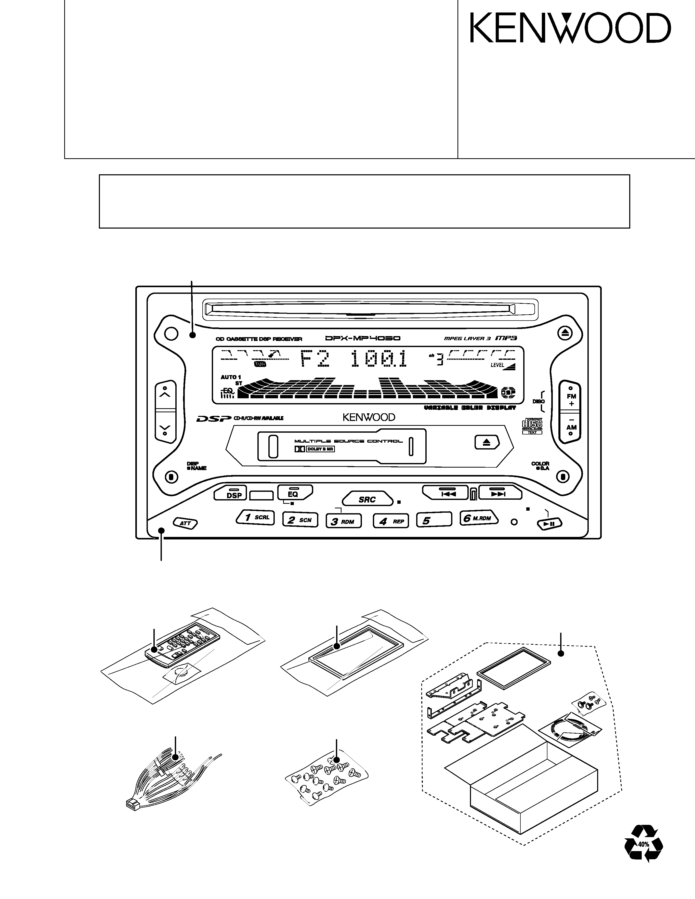
DC CORD ASSY
(E30-4860-08)
SCREW SET
(N99-1724-05)
ESCUTCHEON ASSY
(B07-3046-04)
B NR
AUD
B.S
PWR OFF
MTL
FNC
PANEL
A64-2970-08 : DPX-3030 M type
A64-2971-08 : DPX-MP4030 K,M type
FRONT GRASS ASSY
B10-4377-08 : DPX-3030 M type
B10-4378-08 : DPX-MP4030 K, M type
REMOTE CONTROL ASSY
RC-410
(A70-2025-05)
¥
This service manual not included mechanism information please refers to following service manuals.
¥
CD mechanism operation description, circuit diagram and parts list are please refer to the service manual
X92-4430-00(B51-7889-00 : for DPX-3030) and X92-4460-00(B51-7891-00 : for DPX-MP4030).
¥
Cassette mechanism operation description is please refer to the service manual D40-1132-05 (B51-7505-00).
Illustration is DPX-MP4030
MOUNTING PARTS SET
(W09-0746-08)
2
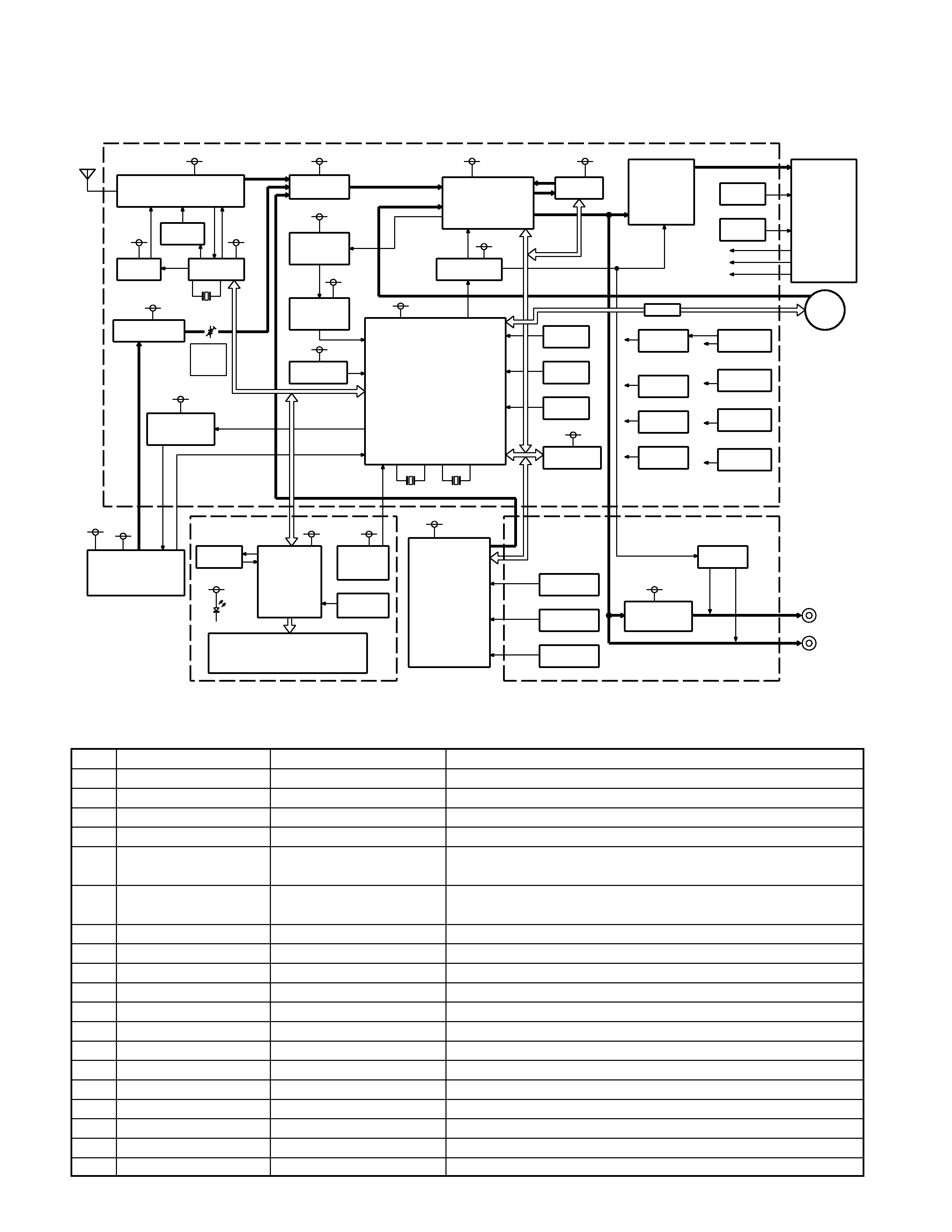
BLOCK DIAGRAM / COMPONENTS DESCRIPTION
AUDIO 8V
SW5V
AUDIO8V
AUDIO8V
SERVO-C
AUDIO8V
AUDIO8V
SW5V
BU5V
BU5V
AUDIO8V
CD CHANGER
BU5V
DSP5V
SW5V
X1
8.38MHz
36.768kHz
X2
SW5V
+B
MOTOR
LED11V
BU5V
BU5V
BU5V
AUDIO8V
(R/N-F)
PRE OUT
(FRONT)
PRE OUT
388mV
MP3
MP3
CD
SP OUT
7.2MHz
X151
Q102
Q151
2SK536
LPF
PLL
LC72135M
IC151
DTA123Y
FM+B
TUNER
(AM/FM/NC/MPX)
TU101
CXA2560Q
DOLBY/EQ/MS
IC201
DRIVER
MOTOR
BA6219BFP-Y
IC251
IC318
INPUT SEL
BA3131
SPE ANA
MIX AMP
IC351
NJM4565MD
BA3830F
BPF
SPE ANA
IC352
RESET
PST3438UL
IC2
MN101C49KWB
u-COM
IC1
(VOL/BAL/EQ/FAD)
TDA7407
E-VOL
IC301
MUTE
HD74HC27FP
IC3
DSP
M65849B
IC331
IC501
POWER AMP
TDA7386
Q601
P-ANT
2SA1703
Q603
P-CONT
2SA1703
16P
CONNECTOR
ACC
ILLUMI
BU-14V
2SC4081
BU-DET
Q611
2SC4081
Q612
ACC-DET
DIMMER
Q613
2SC4081
I/F
BR24C01AF
IC4,5
EEP-ROM
DTA123Y
2SD1760
2SB1565
DSP5V
Q665
AUDIO8V
Q656
SW5V
Q658
2SC4483
SERVO-C
Q650
2SB1565
BU5V
Q652
IMD3A
SW14V
Q654
2SC4483
MOTOR+B
Q663
LED11V
Q660
2SB1184
ILL+B
MECHA.
TN708
CASSETTE
SW
RUBBER
LCD DRIVER
LC75808
IC900
IC901
REMOTE
SENSOR
RS-171
VLCD7.5V
UDZ7.5B
D931
LCD
DXM-6013
CD MECHA.
(DPX-3030)
2SB1565
2SB1184
2SB1565
SERVO7.5V
Q801
SERVO7.5V
Q800
MP3-5V
Q803
Q854A,B
MUTE
DTC343T
Q853A,B/
IC850
PRE OUT SEL
BA3129F
RCA
RCA
DOLBY
ADJ.
LEVEL
13P
DIN
CHANGER
OUT
(DPX-MP4030)
DXM-6403
MAIN PWB
CONTROL PWB
SUB PWB
Ref.No.
Component Name
Application/Function
Operation/Condition/Compatibility
IC1
MN101C49KWB
SYSTEM MICROPROCESSOR
System microprocessor
IC2
PST3438UL
SYSTEM RESET IC
System reset IC
IC3
HD74HC27FP
MUTING SIGNAL SELECTOR Muting signal selector
IC4
BR24C01AF
EEPROM
For security code EEPROM
IC151 LC72135M
PLL
PLL IC (built-in IF counter, reference frequencies, phase comparator,
pulse swallowed)
IC201 CXA2560Q
CASSETTE SYSTEM IC
CT Audio processor (built-in playback EQ, head select sw, Dolby NR
system, muting, music signal interval detection)
IC251 BA6219BFP-Y
MOTOR DRIVER
Sub motor control for Cassette mechanism
IC301 TDA7407
ELECTRONIC VOLUME
Electronic volume (built-in input selector, VR control, muting function, EQ)
IC331 M65849BFP
DSP
DSP IC (built in digital delay, mixing amp, input selector, VR)
IC351 NJM4565MD
1/2VCC, SA MIX AMP
1/2 VCC, spectrum analyzer mix amp
IC352 BA3830F
SPECTRUM ANALYZER IC
Spectrum analyzer BPF (data output to IC1: pin4-pin9)
IC381 BA3131FS
SELECTOR
Audio input selector (from controlled IC1: 86,87PIN)
IC501 TDA7386
AUDIO POWER IC
Audio power IC (built in power standby, muting, protection function)
Q1
DTA124EUA
PRE MUTE SW
Muting sw for pre output signal line
Q2
DTA144EUA
CD CH RESET SW
Reset signal to external CD changer unit
Q3
DTA124EUA
N/F MUTE SW
Muting transistor for N/F output line (from IC1: 83PIN)
Q101 DTC124EUA
MONO/STEREO SW
Tuner mono or stereo mode select sw
Q102 DTA123JK
FM+B SW
Power supply for tuner unit (from controlled IC151: 7PIN)
Q151 2SK536
LPF
LPF for VT voltage (from IC151: 16PIN PD output)
MAIN PWB UNIT
DPX-3030/MP4030
3
COMPONENTS DESCRIPTION
Ref.No.
Component Name
Application/Function
Operation/Condition/Compatibility
Q301 DTC144EUA
E-VOL MUTE SW
Muting transistor for electronic volume
Q351 DTC343TK
SA MUTE
Muting transistor for spectrum analyzer (from IC352)
Q352 2SC4081
SA AGC
AGC transistor for spectrum analyzer
Q502 DTC114YUA
AMP SVR SW
SVR controlled for IC151 (from IC1: 77PIN)
Q601 2SA1703-AN
P-ANT AVR
AVR for P-ANT circuit
Q602 DTC114YUA
P-ANT SW
P-ANT control sw (from IC1: 90PIN)
Q603 2SA1703-AN
P-CONT AVR
AVR for P-CONT circuit
Q604 2SA1576A
P-CONT PROTECTION
Protection of P-CONT circuit
Q605 DTA124EUA
P-CONT PROTECTION
Protection of P-CONT circuit
Q606 DTC114EUA
P-CONT SW
Control sw for P-CONT (from IC1 : 91PIN)
Q611 2SC4081
BU ON/OFF DETECTION SW BU detection sw (to IC1: 26PIN)
Q612 2SC4081
ACC ON/OFF DETECTION SW
ACC detection sw (to IC1: 89PIN)
Q613 DTC144EUA
DIMMER DETECTION SW
Dimmer detection sw (to IC1: 88PIN)
Q650 2SA1703-AN
SERVO C AVR
AVR for CD servo circuit (13.6V)
Q651 2SC4081
BU5V AVR
AVR for BU5V line (5V)
Q652 2SB1565 (E,F)
BU5V AVR
AVR for BU5V line (5V)
Q653 2SC4081
SERVO C AVR
AVR for CD servo circuit (13.6V)
Q654 IMD3AL
14V SW
Control sw for SW14 circuit (from IC1: 96PIN)
Q655 2SD1760
DSP 5V AVR
AVR for DSP 5V line (5V)
Q656 2SB1565 (E,F)
AUDIO 8V AVR
AVR for AUDIO 8V (8V)
Q657 2SC4081
AUDIO 8V AVR
AVR for AUDIO 8V (8V)
Q658 DTA123JK
5V SW
Control sw for SW5V circuit (from IC1: 97pin)
Q659 2SC4081
LED 11V AVR
AVR for 3color LED (12V)
Q660 2SB1184
LED 11V AVR
AVR for 3color LED (12V)
Q663 2SA1703-AN
MOTOR+B AVR
AVR for cassette mechanism motor (14V)
Q664 DTC114YUA
MOTOR+B CONTROL SW
Control sw for cassette mechanism AVR (from IC1: 99PIN)
Q665 IMD2A
LED ON SW
Control sw for 3coler LED AVR (from IC1: 98PIN)
SUB PWB UNIT
Ref.No.
Component Name
Application/Function
Operation/Condition/Compatibility
IC850 BA3129F
REAR/NON FADER SELECTOR SW
Select for pre output
Q800 2SB1565 (E,F)
SERVO 7.5V AVR
AVR for CD mechanism unit (for servo circuit)
Q801 2SB1184
SERVO 7.5V AVR
AVR for CD mechanism unit (for servo circuit)
Q802 2SC4081
SERVO 7.5V AVR
AVR for CD mechanism unit (for servo circuit)
Q803 2SB1565 (E,F)
MP3 5V AVR
AVR for CD mechanism unit (for MP3 circuit)
Q804 2SC4081
MP3 5V AVR
AVR for CD mechanism unit for MP3 circuit)
Q852 DTC124EUA
N/F SEL SW
Control sw for N/F (from IC1: 85PIN)
Q853A DTC343TK
PRE MUTE
Muting sw of pre out line (RL/NFL)
Q853B DTC343TK
PRE MUTE
Muting sw of pre out line (RR/NFR)
Q854A DTC343TK
PRE MUTE
Muting sw of pre out line (L)
Q854B DTC343TK
PRE MUTE
Muting sw of pre out line (R)
CONTROL PWB UNIT
Ref.No.
Component Name
Application/Function
Operation/Condition/Compatibility
IC900 LC75808W
LCD DRIVER
LCD driver, key input signal to system microprocessor
IC901 RS-171
REMOTE CONTROL SENSOR
Remote control sensor
Q900 DTA124EUA
REMO. CONTROL SW
AVR control for remote control sensor
Q902 DTA124EUA
KEY CONTROL SW
Control sw for key matrix line
Q903 2SC4081
LED GREEN CONTROL SW
Green LED driver
Q904 2SC4081
LED BLUE CONTROL SW
Blue LED driver
Q905 2SC4081
LED RED CONTROL SW
Red LED driver
DPX-3030/MP4030
4
MICROCOMPUTER'S TERMINAL DESCRIPTION
Pin No. Pin Name
I/O
Purpose / Description
Processing Operation
1
VREF-
-
GND
Connected to GND
2
REEL-S
I
Cassette mechanism for rotation of reel detection
Rotation of reel pulse from supply part
3
REEL-T
I
Cassette mechanism for rotation of reel detection
Rotation of reel pulse from take-up part
4
SA01
I
Spectrum analyzer input terminal
63Hz input (from IC352,17PIN)
5
SA02
I
Spectrum analyzer input terminal
150Hz input (from IC352,16PIN)
6
SA03
I
Spectrum analyzer input terminal
330Hz input (from IC352,15PIN)
7
SA04
I
Spectrum analyzer input terminal
1KHz input (from IC352,14PIN)
8
SA05
I
Spectrum analyzer input terminal
3.3KHz input (from IC352,13PIN)
9
SA06
I
Spectrum analyzer input terminal
10KHzinput (from IC352,12PIN)
10
VREF+
-
Power supply input terminal
Connected to BU+5V
11
VDD1
-
Power supply input terminal
Connected to BU+5V
12
OSC2
O
Main crystal output terminal
X1 (8.38MHz)
13
OSC1
I
Main crystal input terminal
X1 (8.38MHz)
14
VSS
-
GND
Connected to GND
15
XI
I
Sub crystal input terminal
X2 (32.768KHz)
16
XO
O
Sub crystal output terminal
X2 (32.768KHz)
17
MMOD
I
Memory extension mode setting input terminal
Connected to GND
18
MODE3
I
Operation mode of cassette mechanism detection input terminal SW3 from cassette mechanism
19
MODE1
I
Operation mode of cassette mechanism detection input terminal SW1 from cassette mechanism
20
MODE2
I
Operation mode of cassette mechanism detection input terminal SW2 from cassette mechanism
21
CH-DATAH
O
Control of external CD Changer
Data out put for external CD changer
22
CH-DATAC
I
Control of external CD Changer
Data input from external CD changer
23
CH-CLK
I/O
Control of external CD Changer
CLOCK input / output terminal for external CD changer
24
BEEP
O
BEEP sound output terminal
BEEP ON "H" BEEP OFF "L"
25
SUB M+
O
Motor driver control output terminal
Control of sub motor for cassette mechanism
26
BU-DET
I
BU voltage detection input terminal
L : BU detection
27
CH-REQC
I
Control of external CD Changer
REQ input from external CD changer
28
REMO
I
Remote control signal input terminal
Remote control signal input terminal
29
LCD-DI
I
LCD driver control output terminal
DATA input form LCD driver (from IC900, 97PIN)
30-32 NC
I
-
Connected to GND
33
/RESET
I
System reset input terminal
L : RESET
34
LED RED
O
Adjustment of brightness for LED
PWM output for RED LED
35
SUB M-
O
Motor driver control output terminal
Control of sub motor for cassette mechanism
36
LED BLU
O
Adjustment of brightness for LED
PWM output for BLUE LED
37
ILL ON
O
Illumination LE power supply control output terminal
H : illumination ON
(to operation key)
38
/LCD-INH
O
Control of LCD driver
INH output for LCD driver (to IC900, 96PIN)
39
LCD-CE
O
Control of LCD driver
CE output for LCD driver(to IC900, 98PIN)
40
LED GRN
O
Adjustment of brightness for LED
PWM output for GREEN LED
41
NC
O
-
Connected to GND
42
LCD-DO
O
Control of LCD driver
DATA output for LCD driver (to IC900, 100PIN)
43
LCD-DI
I
Control of LCD driver
DATA input from LCD driver (from IC900, 97PIN)
44
LCD-CLK
O
Control of LCD driver
CLK output for LCD driver (to IC900, 99PIN)
IC1 (MAIN PWB UNIT)
DPX-3030/MP4030
5
MICROCOMPUTER'S TERMINAL DESCRIPTION
Pin No. Pin Name
I/O
Purpose / Description
Processing Operation
45
I2C-SDA
I/O
Control of CD mechanism
E VOL and E2P ROM input / output data for CD mechanism
46
NC
O
-
Connected to GND
47
I2C-SCL
I/O
Control of CD mechanism
E VOL and E2P ROM input / output clock signal for
CD mechanism
48
DMA-SCL
I/O
Control of input/output clock for external ROM
NC
49
DMA-SDA
I/O
Control of input/output data for external ROM
NC
50
JS TYPE1
I
Mode change of Chastity model or on the market model
L : On the market model
51
JS TYPE2
I
Mode change of Chastity model or on the market model
L : On the market model
52
/CD/MP3
I
Mode change for destination
L : DPX-3030 H : DPX-MP4030
53
TYPE1
I
Mode change for destination
L : M type H : K type
54
TYPE2
I
Mode change for destination
L : K type H : M type
55
TYPE3
I
Mode change for destination
L : ALL MODEL
56
MS-MODE
O
Blank detection mode control of TAPE function
L : FF/REW H : PLAY (to IC201, 20PIN)
57
C-F/R
O
Playback head switching control output terminal
L : FORWARD H : REVERES (to IC201, 19PIN)
58
/MTL
O
Playback equalizer control
L : 70usec H : 120usec
59
C-MUTE
O
Muting for cassette
L : MUTE OFF H : MUTE ON (to IC201, 17PIN)
60
DOLBY
O
Dolby NR SW
L : NR OFF H : NR ON (to IC201, 16PIN)
61
/MS IN
I
Blank detection input terminal
Blanc of music : H found in music : L (from IC201,
14PIN)
62
PLL CE
O
Control of PLL IC
CE signal output for PLL IC (to IC151, 2PIN)
63
PLL DI
I
Control of PLL IC
Data signal input form PLL IC (to IC151, 5PIN)
64
PLL DO
O
Control of PLL IC
Data signal output for PLL IC (to IC151, 3PIN)
65
PLL CLK
O
Control of PLL IC
Clock signal output for PLL IC (to IC151, 5PIN)
66
/SD/ST-IND
I
F/E SD, ST-IND input terminal
SEEK function H : receive the radio station,
Tuner mode H : MONO L : Stereo
67
CD-SW2
I
Control of CD mechanism
12cm DISC EJ END detection form CD mechanism
68
CD-SW1
I
Control of CD mechanism
LOADING START SW detection form CD mechanism
69
/CD-MUTE-L
I
Control of CD mechanism
Control of muting signal from CD mechanism
70
/CD-RST
O
System reset output terminal
L : RESET
71
/CD-STOP
O
Control of CD mechanism (for CD STOP mode)
H : PLAY L : STOP
72
CD-SW4
I
Control of CD mechanism
Detection of 8cmDISC EJ END SW input
(form CD mechanism)
73
CD-SW3
I
Control of CD mechanism
Detection of down limit SW input (form CD mechanism)
74
CD-LO/EJ
I/O
Control of CD mechanism
LO/EJ SW input/output control signal (from CD mechanism)
75
CD-LMON
O
Control of CD mechanism
To motor driver SW output
76
/AMP-MUTE
O
Control of power pack IC for muting mode
L : MUTE ON (to IC501 : 22PIN)
77
AMP-SVR
O
Control of power pack IC for SVR mode
Control of pop noise for Power pack IC
(power ON/OFF function)
78
/AMP-STBY
O
Control of power pack IC for standby mode
L : Standby H : AMP ON (to IC501, 4PIN)
79
DSP-DATA
O
Control of DSP
Data output for DSP IC (to IC331, 5PIN)
80
DSP-STB
O
Control of DSP
Strobe signal for DSP IC (to IC331, 4PIN)
81
DSP-CLK
O
Control of DSP
Clock signal for DSP IC (tor IC331, 3PIN)
82
SA-MUTE
O
Muting for spectrum analyzer input signal
NC
DPX-3030/MP4030