COMPACT DISC PLAYER
DPF-1030/1030E/1030-S
DPF-2030/2030E/2030-S
SERVICE MANUAL
© 2000-3/B51-5603-00 (K/K) 2100
KENWOOD-Corp. certifies this equipment conforms to DHHS
Regulations No. 21 CFR 1040. 10, Chapter 1, Subchapter J.
DANGER : Laser radiation when open and interlock defeated.
AVOID DIRECT EXPOSURE TO BEAM.
In compliance with Federal Regulations, following are repro-
ductions of labels on, or inside the product relating to laser
product safety.
Refer to DP-3080MK
/3090 Service manual (B51-5349-00),
if you require disassembly for repair.
* Refer to parts list on page 14.
70%
POWER
- ON OFF
PHONES
P.MODE
EDIT
CHECK
CLEAR
PEAK SEARCH
TIME DISPLAY
OPEN/CLOSE
REPEAT
RANDOM
0
76
4¢
1¡
OUTPUT
OPTICAL
DIGITAL
OUTPUT
SYSTEM CONTROL
L
R
TEXT
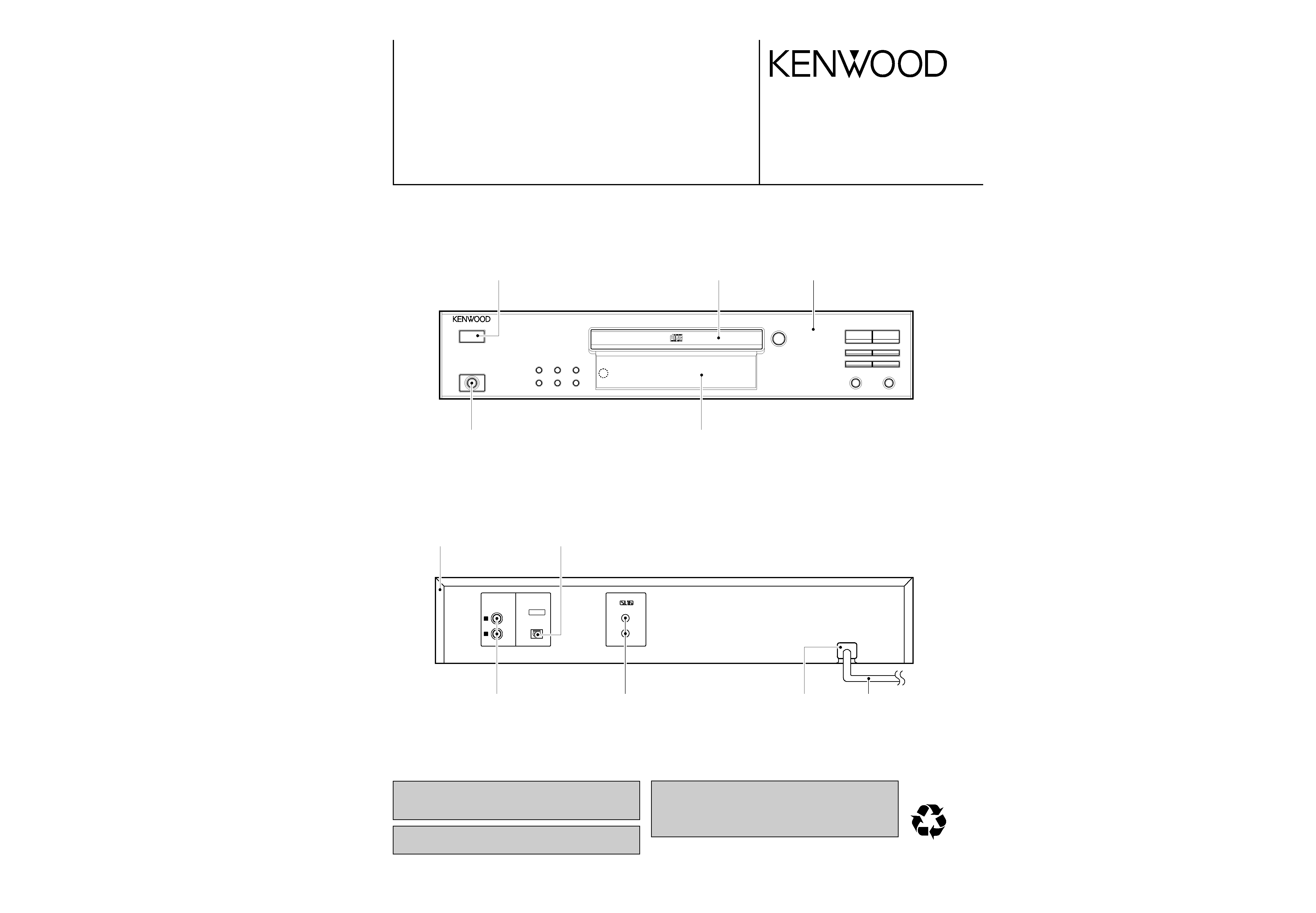
Power Knob *
(K29-)
H/P jack
(E11-0345-08)
Tray cover *
(A21-)
FL window
(B10-3611-08)
Front cab ass'y *
(A60-)
Top cabinet *
(A01-)
Digital output jack
(W02-2752-08)
AC power cord *
(E30-)
System jack
(E11-0188-05)
Pin jack
(E63-1081-08)
AC power cord bushing
(J42-0083-05)
DPF-1030/2030
2
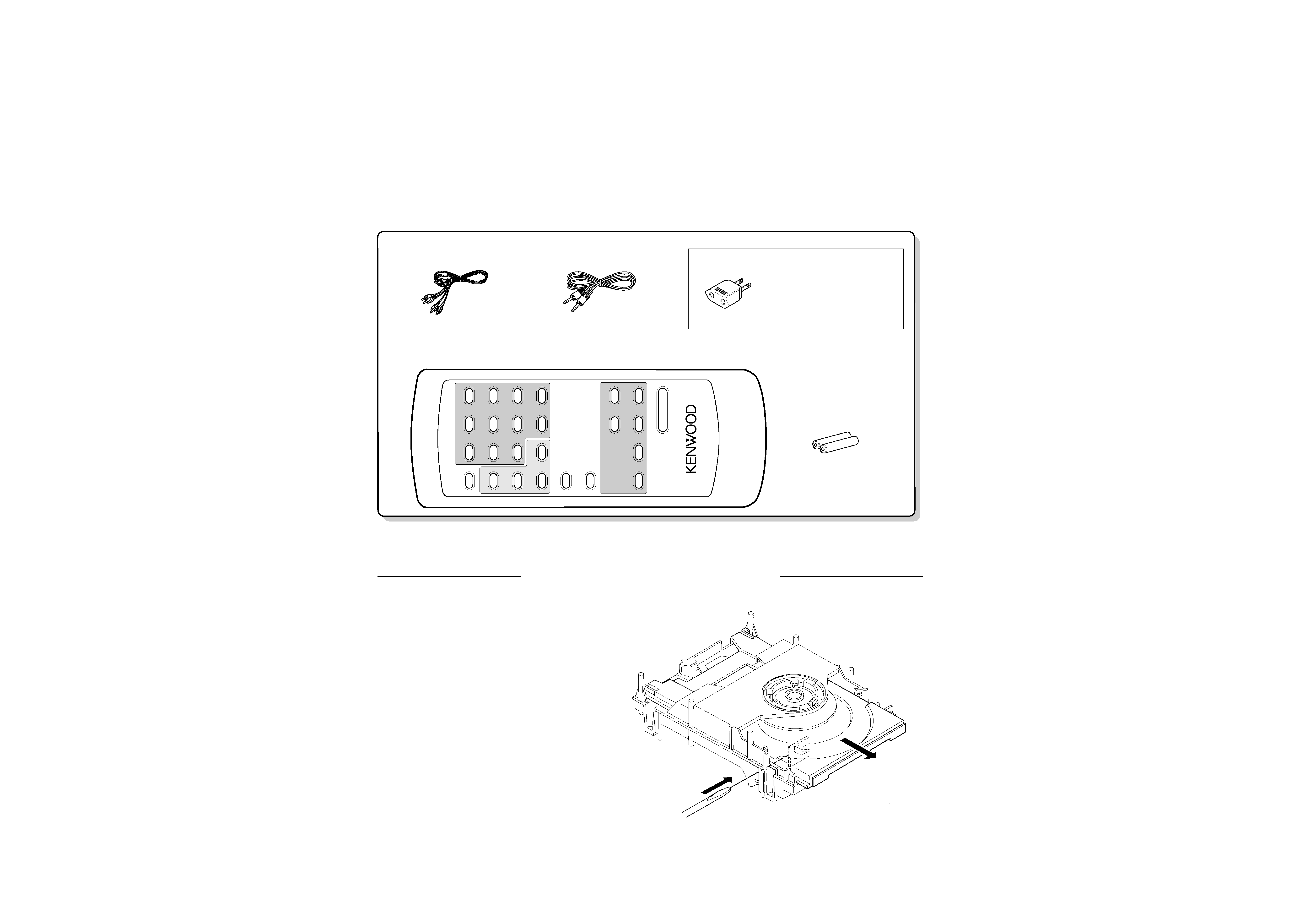
CONTENTS / ACCESSORIES
DISASSEMBLY FOR REPAIR
CONTENTS / ACCESSORIES .................................. 2
DISASSEMBLY FOR REPAIR....................................2
CIRCUIT DESCRIPTION ............................................3
ADJUSTMENT ............................................................4
PC BOARD ................................................................ 5
SCHEMATIC DIAGRAM ............................................ 7
EXPLODED VIEW ....................................................12
PARTS LIST..............................................................14
SPECIFICATIONS ......................................Back cover
Contents
1. How to open tray when tray not come out.
1. Insert the screw driver to left side hole of mechanism ass'y.
2. While pushing the rack gear fully right wards, then the tray pull.
Audio
(E30-2913-08)
(A70-1414-08) : RC-P0715
(DPF-2030 only)
Battery cover : (A09-1190-08)
(E30-2912-08)
cord .................. (1)
System control cord ...... (1)
Remote control unit ......... (1)
Batteries
(DPF-2030 only)
(R6/AA) ........ (2)
AC
(E03-0115-05)
plug adaptor .............. (1)
Use to adapt the plug on the
power cord to the shape of the
wall outlet.
(Accessory only for regions where
use is necessary.)
TIME
DISP
12
3
P.MODE
45
6
EDIT
78
9
CLEAR
RANDOM
REPEAT
OUTPUT
LEVEL
DOWN
U
P
CHECK
0
+10
76
4
¡
1¢
REMOTE
CONTROL
UNIT
RC-P0715
Accessories
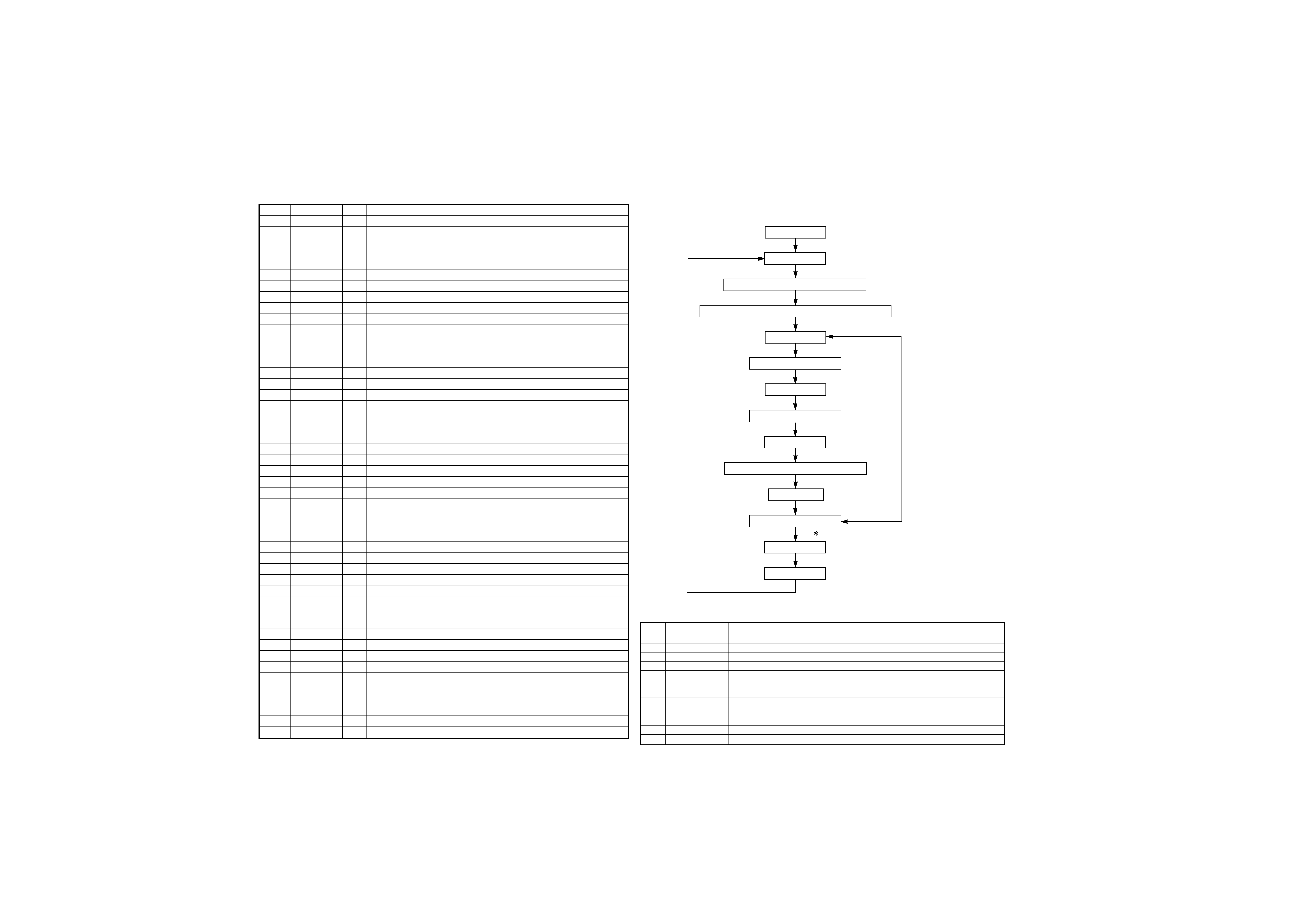
Pin No.
Pin Name
I/O
Description
1-6
6G-1G
O
FL grid control port.
7
NC
-
Unused.
8
VDD
-
Power supply(+5V).
9-11
-
-
Connected to ground.
12
C-RESET
O
DSP signal output.
13
S-MUTE
O
Muting signal output for system.
14
NC
-
Unused.
15
TEXT
I
Text copy detection.
16
-
-
Connected to ground.
17
RESET
I
Hardware reset signal input.
18
LD CLOSE
O
Tray motor control.
19
LD OPEN
O
Tray motor control.
20
AVSS
-
Connected to ground.
21
-
-
Connected to ground.
22
PU IN SW
I
Pickup location.
23
OPEN SW
I
Tray open switch input.
24
CLOSE SW
I
Tray close switch input.
25-28
KEYO-3
I
Key input port.
29
AVDD
-
Power supply(+5V).
30
AVREF
-
Reference voltage(+5V).
31,32
XT1,2
-
Connected to ground.
33
VSS
-
Connected to ground.
34,35
XO,1
-
X'tal 4.19MHz.
36
WRQ
I
Sub code Q output.
37
COIN
O
Command data to DSP.
38
16BIT
-
Unused.
39
HF
-
Connected to ground.
40
NC
-
Unused.
41
CQCK
O
Clock output to DSP.
42
SQOUT
I
SQ data to dsp.
43
RWC
O
Reading/writing control port.
44
GND
-
Connected to ground.
45
S BUSY
I/O
System control data.
46
S DATA
I/O
System control status.
47
RMC
I
Remote control signal input.
48
GND
-
Connected to ground.
49
TRY L/H
O
Tray motor speed control.
50
SL-
O
Sled motor control port(reverse).
51
SL+
O
Sled motor control port(forward).
52
VDD
-
Power supply(+5V).
53-59
NC
-
Unused.
60
DRF
I
CD focus OK signal input.
61
NC
-
Unused.
62-70
a-j
O
FL segment(a-j) control port.
71
VLOAD
-
Power supply(-30V).
72,73
k,l
O
FL segment(k,l) control port.
74-77
NC
-
Unused.
78-80
9G-7G
O
FL grid(9G-7G) control port.
No.
INPUT KEY
FUNCTION
DISPLAY
1
PLAY(1ST)
LASER ON
LD ON
2
PLAY(2ND)
FOCUSING SERVO ON
FS ON
3
PLAY(3RD)
PLAY(TRACKING SERVO OFF)
Sb off
4
PLAY(4TH)
PLAY(TRACKING SERVO ON)
TN0. And Time
5
UP
In the stop mode. Moves the pickup slightly
toward the outer position disc.
When tracking servo is ON, set the track number up.
6
DOWN
In the stop mode. Moves the pickup slightly
toward the inner position disc.
When tracking servo is ON, set the track number up.
7
STOP
Laser off, focusing servo off, tracking servo off.
All segments
8
OPEN/CLOSE
In the stop mode, Tray is opened or closed.
All segments
DPF-1030/2030
3
CIRCUIT
DESCRIPTION
STOP key enable
If key in STOP,
return to start
stage.
START
FL LIGHT UP ALL
Tray open/close enable (display no change)
For move Pick-up, UP and DOWN key enable only stop mode
Key in PLAY
Laser ON , Display [LD ON]
Key in Play
Focus ON, Display [FS ON]
Key in PLAY
PLAY (Track servo OFF) Display [Sb OFF]
Key in PLAY
Play (Track servo ON)
Key in STOP
STOP
WITH TIME DISPLAY
Setting the test mode
: While pressing the STOP key, press the POWER switch.
Test mode will be cancelled by pressing the
POWER switch key in the stop mode.
When play mode, UP key enable
but only track jump.
3. Key function in test mode
2. Test mode
1. Pin description of microprocessor
DPF-1030/2030
4
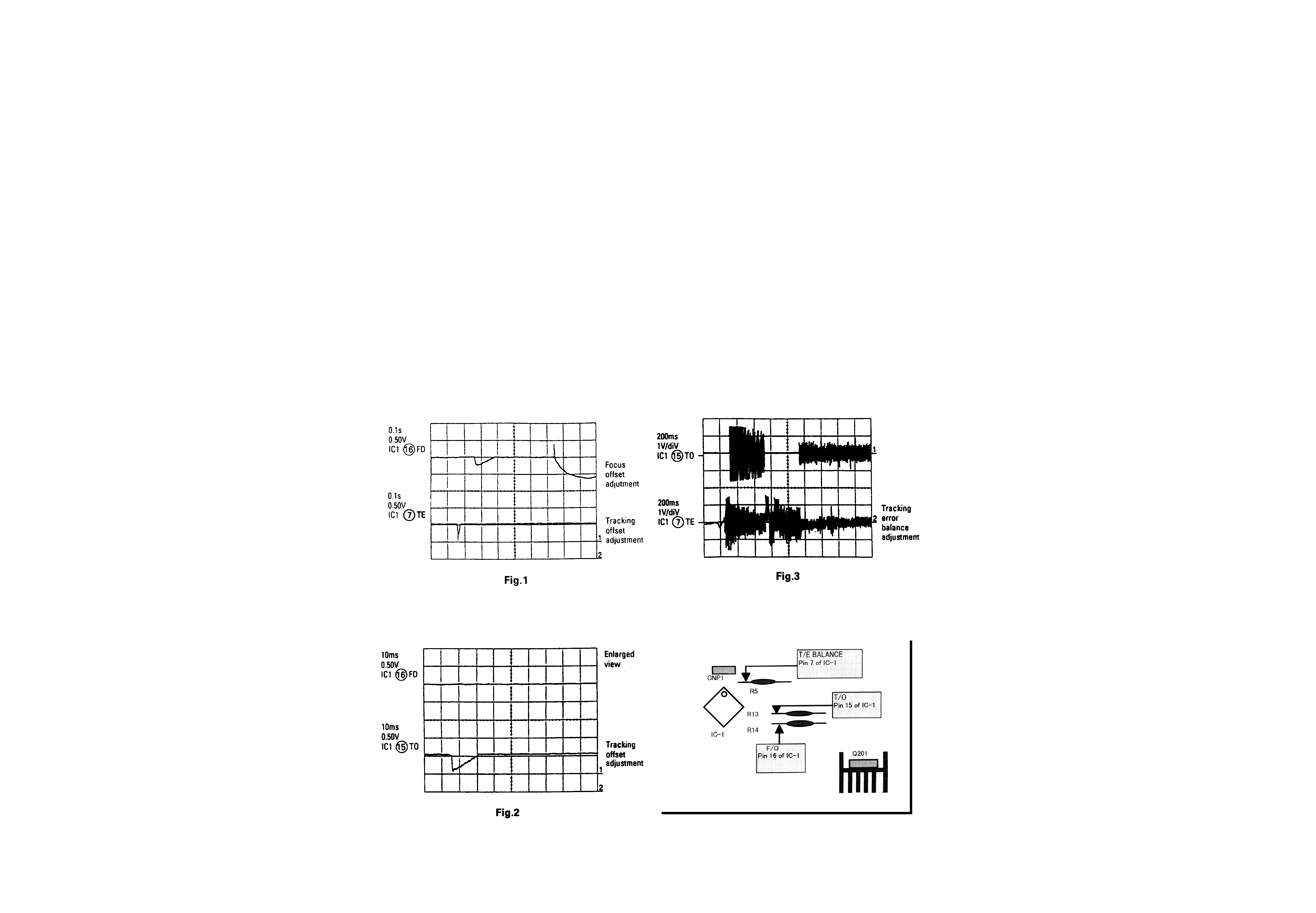
ADJUSTMENT
CD section
Since this CD system incorporates the following automatic
adjustment function, when the pickup is replaced, it is not neces-
sary to readjust it
Since this CD unit does not need adjustment, the combination
of PWB and laser pickup unit is not restricted.
·Automatic adjustment item
1. Focus offset(Fig.1)
2. Tracking offset(Fig.2)
3. E/F balance (Tracking error balance) (Fig.3)
4. RF level AGC function (HF level : constant)
5. RF level automatic follow-up of the tracking gain
This automatic adjustment is performed each time a disc is
changed. Therefore, each disc is played back using the optimal
settings
Fig.4 Checking points
ACE
G
I
BD
F
H
J
2
1
3
5
7
4
6
R406
J401
SW407
RANDOM
SW408
REPEAT
SW405
REWIND
SW403
LAST
SW420
CNP401
2
1
29
1
1
19
5
2
O
G
I
28
1
28
65
64
41
1
4
3
1
E
B
E
E
B
B
E
B
E
E
B
E
B
I
I
I
G
G
G
O
O
O
E
E
B
B
1
7
B
8
5
1
1
1
1
18
36
19
1
1
18
7
6
16
17
32
33
48
49
64
80
65
64
41 40
25
24
4
85
40
25
24
34
2
1
1
3
2
1
7
1
2
DISPLAY-2 PWB
POWER PWB
DISPLAY-1 PWB
MAIN PWB
PHONES
SYSTEM
CONTROL
DIGITAL
OUT
OUTPUT
OPTICAL
POWER
28
29
OPEN/CLOSE
SW401
STOP
SW406
FORWARD
SW404
NEXT
SW402
PLAY
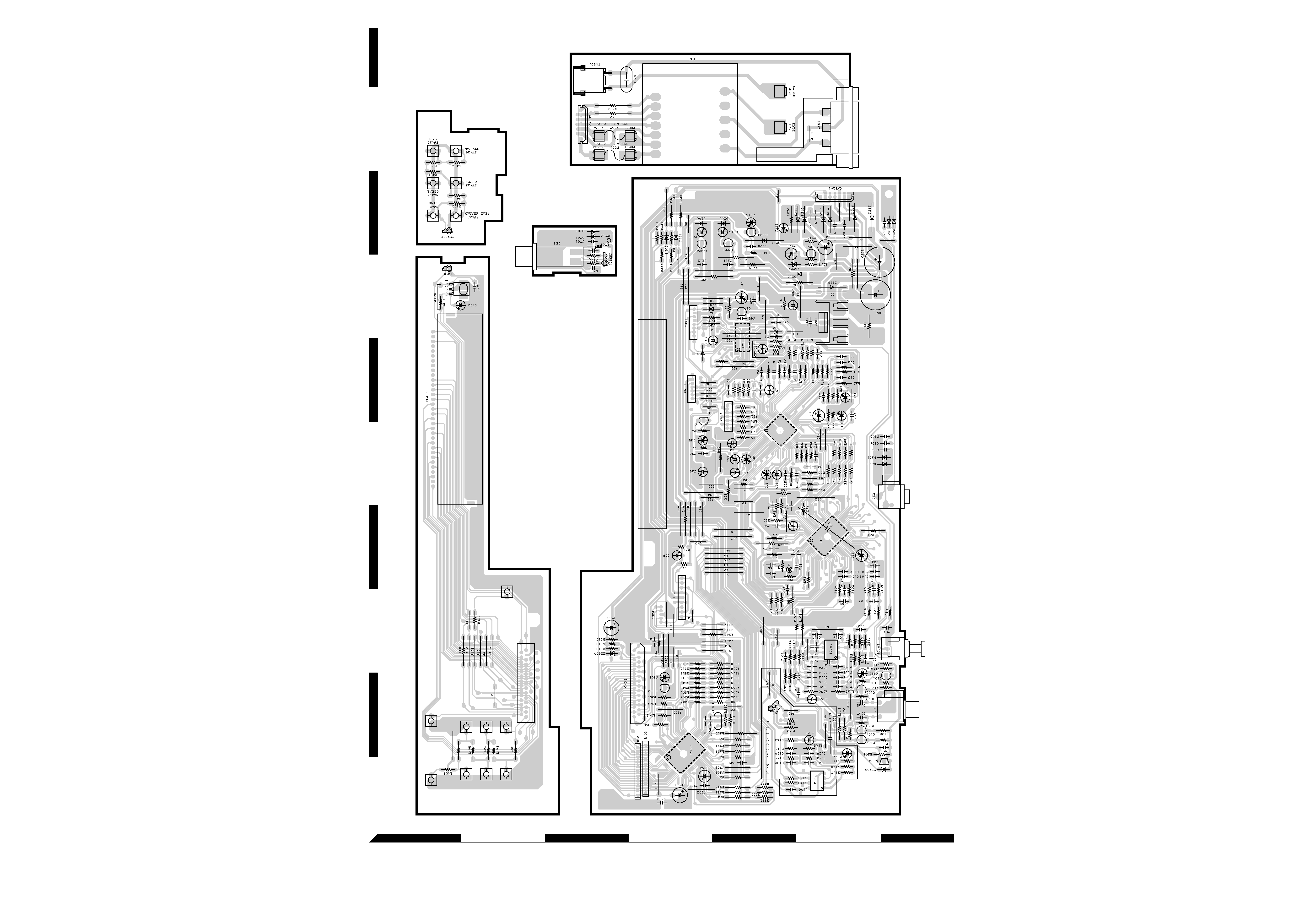
Refer to the schematic diagram for the value of resistors and capacitors.
PC BOARD(Component side view)
5
6