PORTABLE CD PLAYER
DPC-X301/X507/X602
SERVICE MANUAL
© 1999-3/B51-5514-00 (K/K) 2338
SPECIFICATIONS
* Refer to parts list on page 12~.
In compliance with Federal Regulations, following are
reproductions of labels on, or inside the product relating to laser
product safety.
KENWOOD-Corp. certifies this equipment conforms to DHHS
Regulations No. 21 CFR 1040. 10, Chapter 1, Subchapter J.
DANGER : Laser radiation when open and interlock defeated.
AVOID DIRECT EXPOSURE TO BEAM.
Format
System ....................................................................................................... Compact disc digital audio system
Laser .................................................................................................................................. Semiconductor laser
Audio
Frequency response ..................................................................................................... 20 Hz to 20 kHz,
±3 dB
PHONES outpuyt level (16
, 1 kHz ) ........................................................................................ 8 mW + 8 mW
Line output/impedance .............................................................................................................. 0.55 Vrms/1 k
Power supply
External DC supply ...................................................................................................................... 4.5V to 6 V DC
Rechargeable batteries (NB-88 ) x 2 or 4 .............................................................................................. DC 2.4 V
Commercially-available alkaline batteries (LR6/AA) x 2 or 4 ................................................................. DC 3 V
Battery life (continuous repeat playback)
(Figures inside parentheses show the performance when the D.A.S.C. is ON.)
Commercially-available alkaline batteries (LR6/AA) x 2 ............................................................... Approx. 12 (9.5) Hours
Commercially-available alkaline batteries (LR6/AA) x 4 ................................................................ Approx. 25 (20) Hours
Rechargeable batteries (NB-88) x 2 .............................................................................................. Approx. 5.5 (4.5) Hours
Alkaline batteries (LR6/AA) x 2 and rechargeable batteries (NB-88) x 2 ....................................... Approx. 18 (15) Hours
Dimensions (W x H x D) (DPC-X301) ...................................................................132 mm x 32.5 mm x 153 mm
(5 - 3/16" x 1 - 1/4" x 6")
Dimensions (W x H x D) (DPC-X507/X602) ..........................................................132 mm x 29.5 mm x 153 mm
(5 - 3/16" x 1 - 3/16" x 6")
Weight (net) (DPC-X301) ................................................................................................................ 272 g (9.6 oz)
Weight (net) (DPC-X507/X602) ....................................................................................................... 260 g (9.2 oz)
Notes
Notes
1. KENWOOD follows a policy of continuous advancements in development. For this reason specifications may
be changed without notice.
2. The full performance may not be exhibited in an extremely cold location (under a water-freezing temperature).
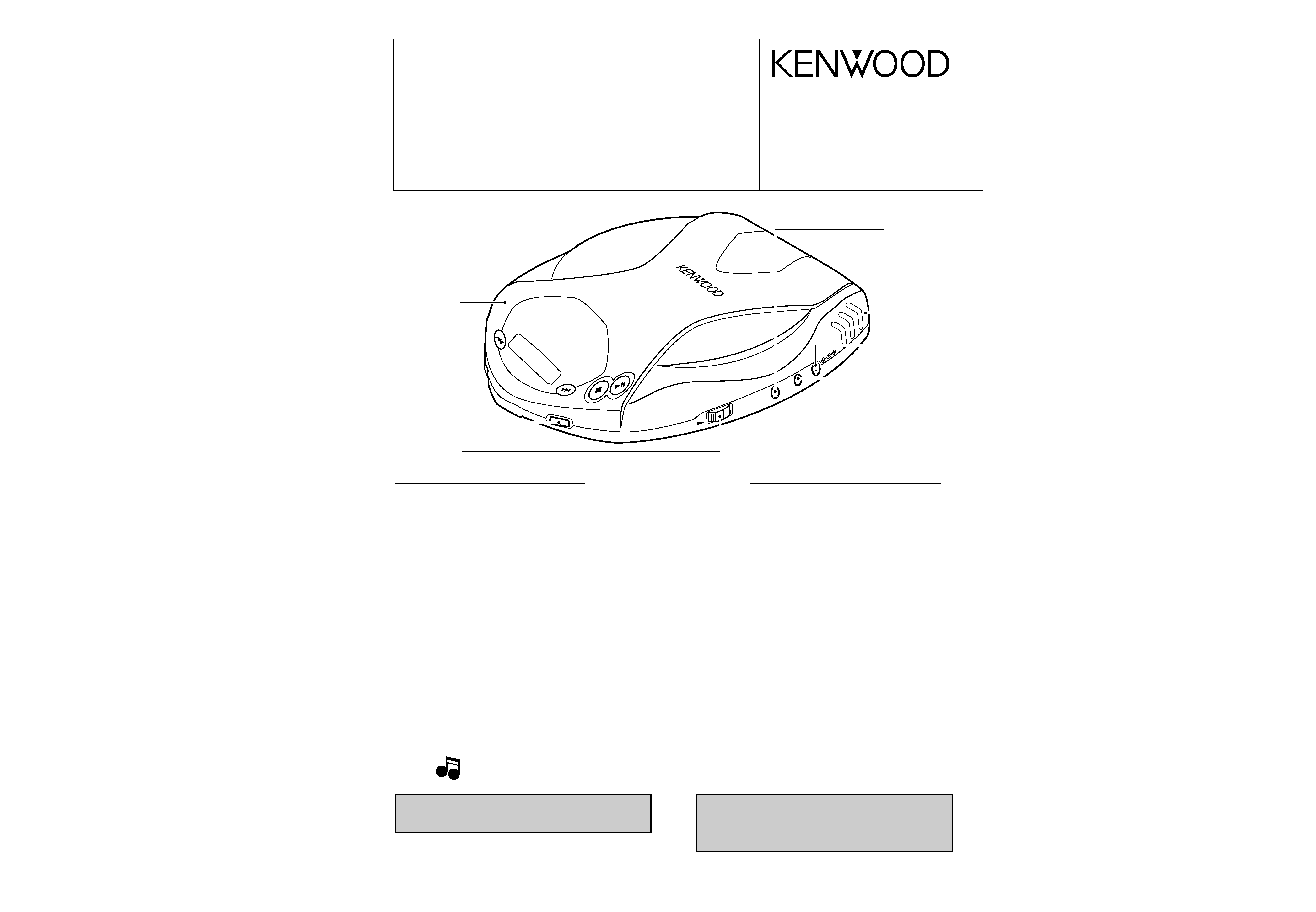
VOLUME
PHONES
LINE
OUT
DC-IN
Top cabinet *
(A02-)
DC jack
(E03-0356-08)
Line out phone jack
(E11-0354-08)
Phone jack
(E11-0372-08)
Variable resistor
(R31-0086-08)
Knob (REPEAT)
(K27-2327-08)
CD door ASSY *
(A52-)
cover1p 99.10.299:52AM y[W 1
ABBREVIATION
3
5
6
MODEL
DPC-X301
DPC-X507
DPC-X602
DESTINATIONS
J
P
M
X
T
E
J
K
P
M
X
T
E
K
P
M
X
DASC
SW(HI-OFF-ST(16M)
-----
-
YES
YES YES YES
YES
YES
YES
YES YES YES YES
LINE OUT JACK(J105)
YES YES YES YES YES
YES
YES
YES YES YES
YES
YES
YES
YES YES YES YES
REMOCON
JACK(J103)
-----
-
YES
--YES
YES
-
-
----
CAR BATTERY ADP.
-----
-
-
--
----
YES YES YES YES
CAR SACETTE ADP.
-----
-
-
--
----
YES YES YES YES
-
-
-
----
RECHAGEABLE BATTERY
----
NB-88 -
NB-88 -
-
NB-88 NB-88 NB-88 -
----
INNER
HEADPHONE(SHORT)
-----
-
YES
--YES
YES
-
-
----
INNER
HEADPHONE(LONG)
YES -
YES YES YES
YES
-
-
-
-
-
YES
YES
-
-
YES YES
OPEN HEADPHONE
-
YES -
-
-
-
-
YES YES ----
YES YES -
-
REMOCON WIRED
-----
-
3-KEY -
-
LCD
LCD
-
-
----
COLOR*
S
S
W
W
BL
S,BL
L,W
S
S
BL
BL
S
S,BL
SSSS
* (S)=SILVER, (W)=WHITE, (L)=BULE, (BL)=BLACK
2
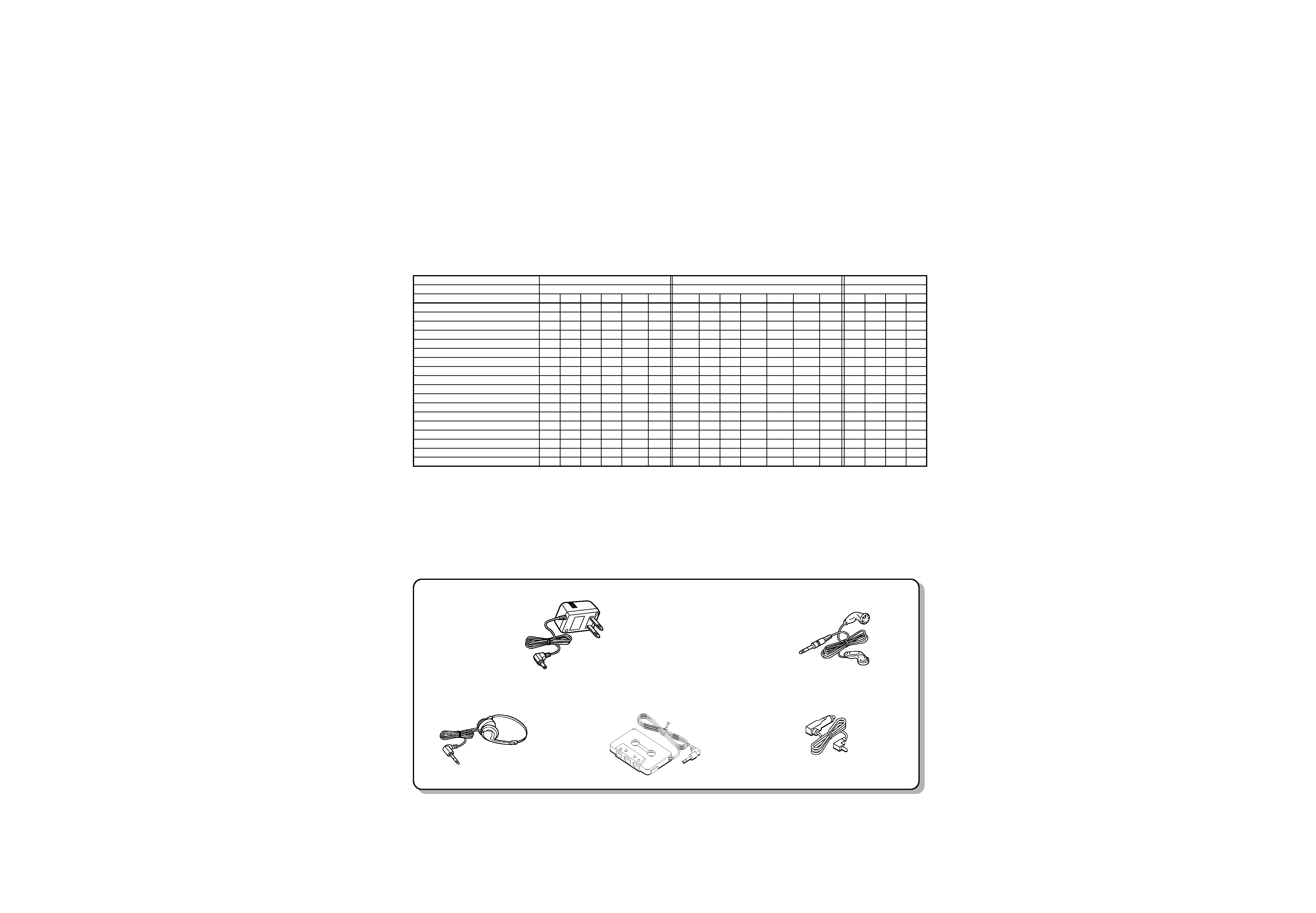
CONTENTS / ACCESSORIES
DPC-X301/X507/X602
SPECIFICATIONS ...................................Top cover
CONTENTS / ACCESSORIES ..............................2
CIRCUIT DESCRIPTION .......................................3
PC BOARD ............................................................5
SCHEMATIC DIAGRAM ........................................7
EXPLODED VIEW ...............................................11
PARTS LIST.........................................................12
Contents
Model feature list
AC adapter ..................................................................(1)
(W08-0658-08) : E3,E5
(W09-1251-05) : K5,K6,P6
Innerphone..........................................(1)
(W01-0925-05) : E3,E5
Car battery adapter ........................(1)
(W01-0921-05) : K6,P6
Car cassette adapter......................(1)
(W01-0922-05) : K6,P6
Headphone ....................................(1)
(W01-0924-05) : K5,K6,P6
Accessories
cover1p 99.10.299:52AM y[W 2
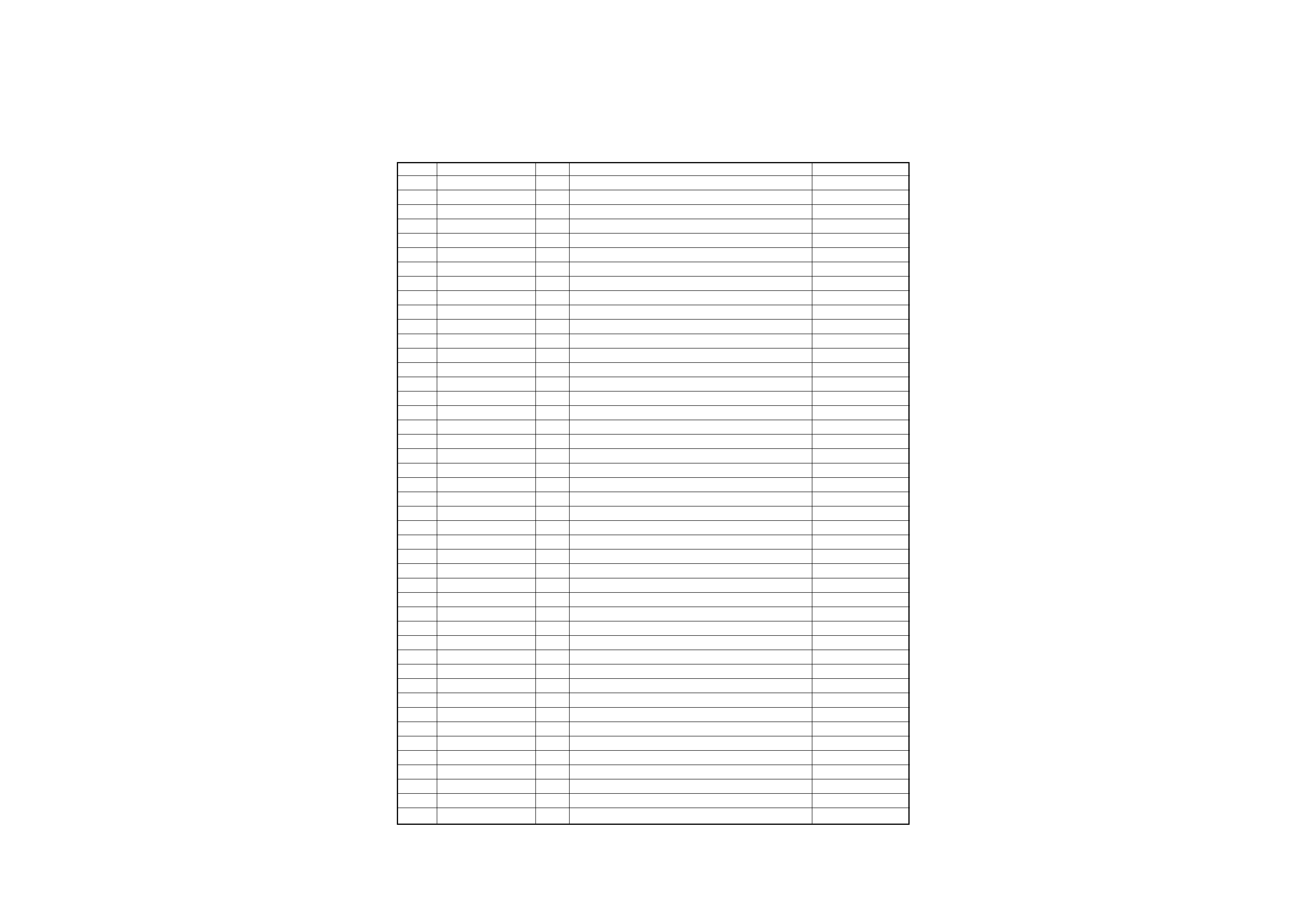
Pin No.
Name
I/O
Description
Remarks
1-4
COM1-4
O
LCD common signal
5
VLC3
GND
6,7
VLC1,2
LCD driving bias control
8
VDD
Power supply(+2.8V)
9
OSC2
No use
10
SMCK
I
External system clock(4.2336MHz)
11
VSS
GND
12
X1
GND
13
X0
No use
14,15
MMOD,VREF
GND
16
KEY1
I
Key input
17
KEY2
I
Remocon key input port
18
RECHARGE OUT
O
Rechargeable detection port
19
BATT
No use
20
HOLD
I
Key hold on/off control
ON=H
21
DOOR
I
Door switch detection port
OPEN=H
22
DA SCST
I/O
DASC switch detection port(ST)
23
DA SCHI
I
DASC switch detection port(HI)
24
VREF+
Power supply(+2.8V)
25
P00
No use
26
SUBQ
I
Sub-Q data input signal port(to MN662746RPK1)
27
SQCK
I
Sub-Q data read timing clock port(to MN662746RPK1)
28
MDATA
O
Data signal port(to MN662746RPK1)
29
P04
No use
30
MCLK
O
Clock signal port(to MN662746RPK1)
31
P06
No use
32
RESET
I
System reset port
33-37
P10-14
No use
38
BLKCK
I
Sub-Q signal read require port
39
P21
No use
40
REM IN
I
Remocon data input port
41,42
P23,24
No use
43
YMCLK
O
Clock signal port to SM5903AF
44
YMDATA
O
Audio signal port to SM5903AF
45
YMLD
O
Latch signal port to SM5903AF
46
YD MUTE
O
Audio signal mute control port
ON=H
47
ZSENSE
O
Sensitive signal port to SM5903AF
48
NRESET
O
System reset port to SM5903AF
49,50
P53,54
No use
51
POWER
O
Power supply control port
52
REM DATA
O
Remocon data output port
53
CONT
O
DASC control output port(HI/ST)
ON=H
54
BBS
O
BBS control
ON=L
55
LMT
I
Limit switch detection port
56
EMP
O
Battery level detection port
LOW BATT=H
3
DPC-X301/X507/X602
CIRCUIT DESCRIPTION
1. Microprocessor : MN101C16ATA2
1-1 Pin description
cover1p 99.10.299:52AM y[W 3
4
DPC-X301/X507/X602
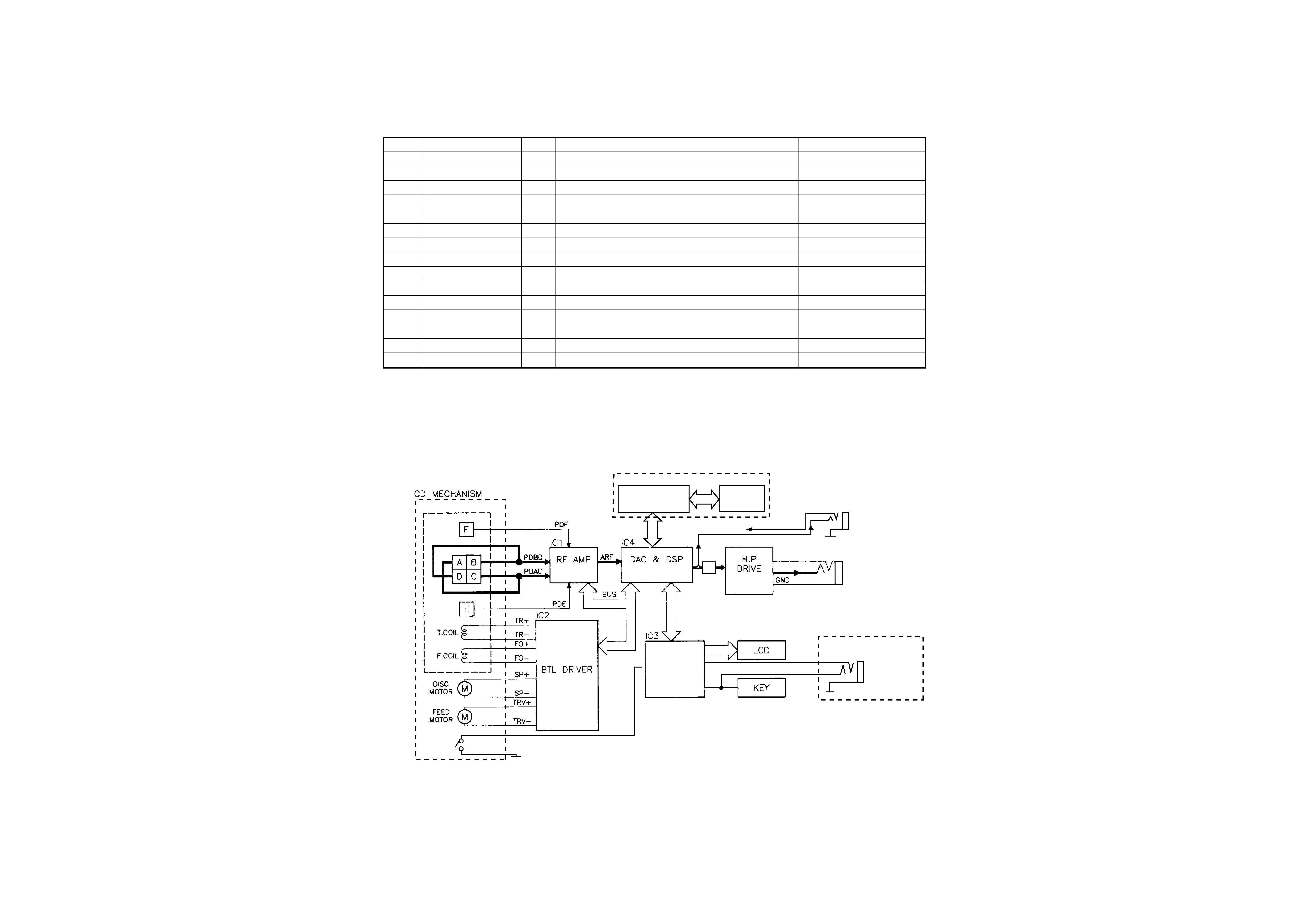
CIRCUIT DESCRIPTION
EXCEPT FOR DPC-X301
IC5
SHOCKPLOOF
SM5903AF
IC6
DRAM
AN8789FB
(KSM-542AAA)
/ / /
/ / /
/ / /
FROM IC4 (Rch)
J105
LINE OUT
J102
Rch
Lch
H. P JACK
NJM2073M
VOLUME
J103
DPC-X507(M,X type) only
REMOTE
LMT.
SW
AN8838SB
Lch
IC9
µ-COM
MN101C16A
TA2
MM662746RPK1
Pin No.
Name
I/O
Description
Remarks
57-59
P66,67,70
No use
60
RECHARGE
I
Rechargeable battery detection port
61
LIGHT OUT
No use
62
MLD
O
Latch signal port(to MN662746RPK1)
63
SENSE
I
Sensitive signal port
64
FLOCK
I
Focus servo
IN=L
65
TLOCK
I
Tracking servo
IN=L
66
STAT
I
Status signal port
67
RST
O
Reset signal port(to MN662746RPK1)
68-71
P83-86
No use
72
DIGITAL OUT
O
No use
73
P81
I
Memory selector
NO=H,16M=L
74
P80
I
Memory selector
NO=L,16M=L
75-85
SEG15-25
No use
86-100
SEG0-14
O
LCD segment signal
1-2 Microprocessor periphery block diagram
cover1p 99.10.299:52AM y[W 4
4
1
5
IC9
8
22
12
14
1
25
1
51
75
100
76
26
50
60
41
1
22
12
34
44
11
1
14
26
13
1
23
33
20
40
21
61
80
15
28
34
44
1
IC2
IC1
IC3
IC4
IC5
IC6
11
33
23
REPEAT
REMOTE
VOLUME
LINE OUT
PHONES
DC IN
DOOR
SW
P.MODE
B.B
1
19
ON OFF
HOLD
ON OFF
ESP SW
IC7
1
26
13
14
4
1
5
IC9
8
22
12
14
1
25
1
51
75
100
76
26
50
60
41
1
22
12
34
44
11
1
14
26
13
1
23
33
20
40
21
61
80
15
28
34
44
1
IC2
IC1
IC3
IC4
IC5
IC6
11
33
23
REPEAT
REMOTE
VOLUME
LINE OUT
PHONES
DC IN
DOOR
SW
P.MODE
B.B
1
19
ON OFF
HOLD
ON OFF
ESP SW
IC7
1
26
13
14
ACE
G
I
BD
F
H
J
2
1
3
5
7
4
6
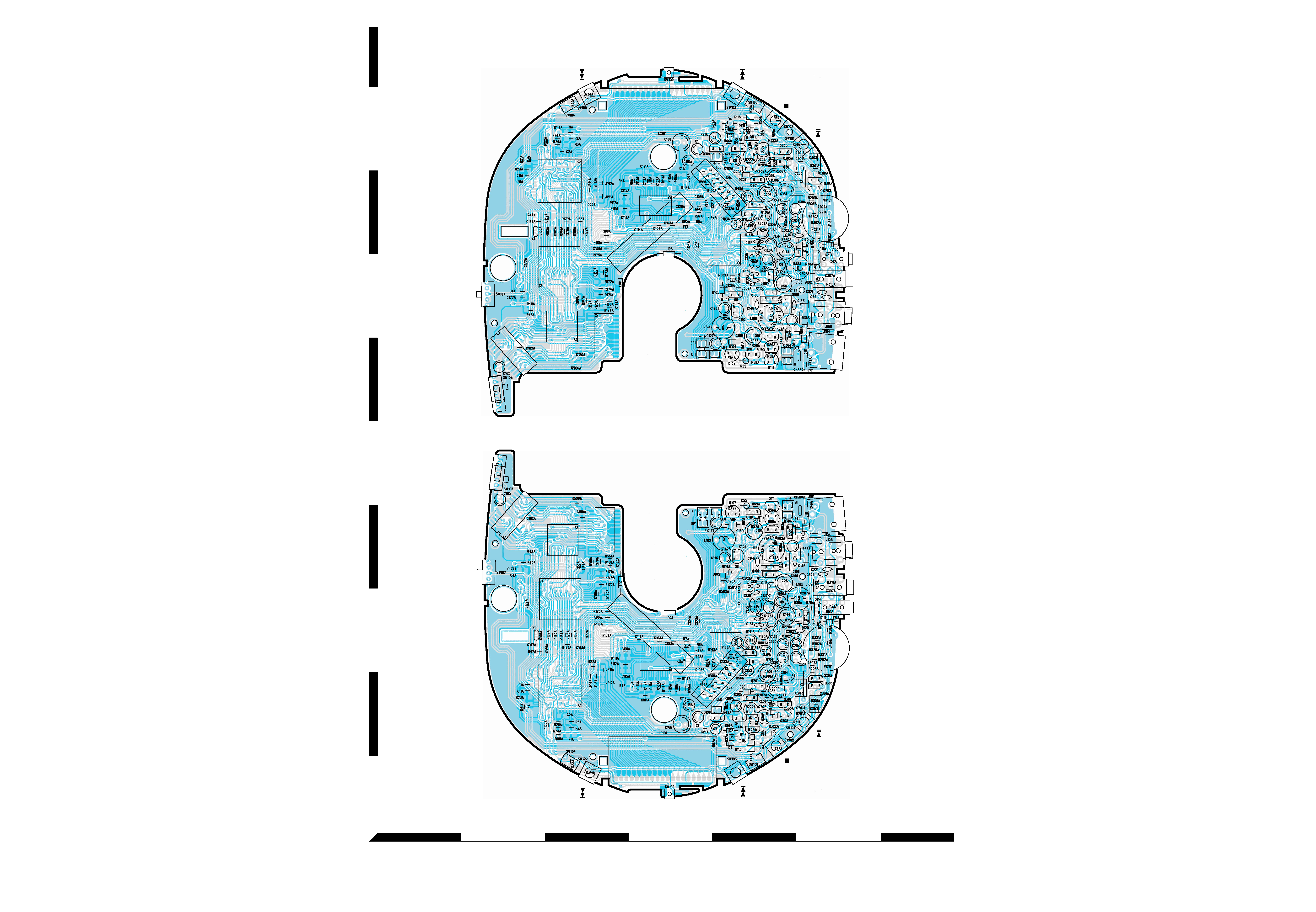
Refer to the schematic diagram for the value of resistors and capacitors.
PC BOARD (Component side view)
PC BOARD (Foil side view)
5
6