PORTABLE CD PLAYER
DPC-781/782/981
SERVICE MANUAL
© 1997-10/B51-5379-00 (K/K) 3176
Format
System..............................................................................................................................................................Compact disc digital audio system
Laser ......................................................................................................................................................................................Semiconductor laser
Audio
Frequency response ...........................................................................................................................................................20 Hz ~ 20 kHz, ±3 dB
Headphone output (16
, 1 kHz) .................................................................................................................................................10 mW + 10 mW
(Headphone output level / impedance ..................................................................................................................................max. 450 mV / 2.2
)
[For CHINA and Duty Free Shop in JAPAN]
Digital output optical..............................................................................................................................-21 dBm ~ -15 dBm (wave lenght 660nm)
[For other countries]
LINE output level / impedance.......................................................................................................................................................550 mV / 702
Power supply
External DC supply ............................................................................................................................................................................DC 4.5 ~ 6 V
Rechargeable batteries ............................................................................................................................................................................DC 2.4 V
Commercially - available alkaline batteries .................................................................................................................................................DC 3 V
Battery life (continuous playback) Repeat playback stops after 16 times.
(Figures inside parentheses are the values when D.A.S.C. is ON.)
Commercially-available alkaline batteries (LR6 / AA) x 4 ....................................................................................................Approx. 40 (34) hours
Commercially-available alkaline batteries (LR6 / AA) x 2 .................................................................................................Approx. 18.5 (17) hours
Rechargeable batteries (NB - 130) x 2...............................................................................................................................Approx. 9.0 (8.0) hours
With 2 commercially-available alkaline batteries and rechargeable batteries...................................................................Approx. 27.5 (25) hours
Dimensions (W x H x D)........................................................................................................................................133.6 mm x 26.5 mm x 151.8 mm
Weight (net) .........................................................................................................................................................................................270 g (9.5 oz.)
SPECIFICATIONS
1. KENWOOD follows a policy of continuous advancements in development. For this reason specifications may be changed without
notice.
2. Sufficient performance may not be exhibited at extremely cold locations (where water freezes.).
Notes
Notes
* Refer to parts list on page 15.
In compliance with Federal Regulations, following are reproduc-
tions of labels on, or inside the product relating to laser product
safety.
KENWOOD-Crop. certifies this equipment conforms to DHHS
Regulations No. 21 DFR 1040. 10, Chapter 1, Subchapter J.
DANGER : Laser radiation when open and interlock defeated.
AVOID DIRECT EXPOSURE TO BEAM
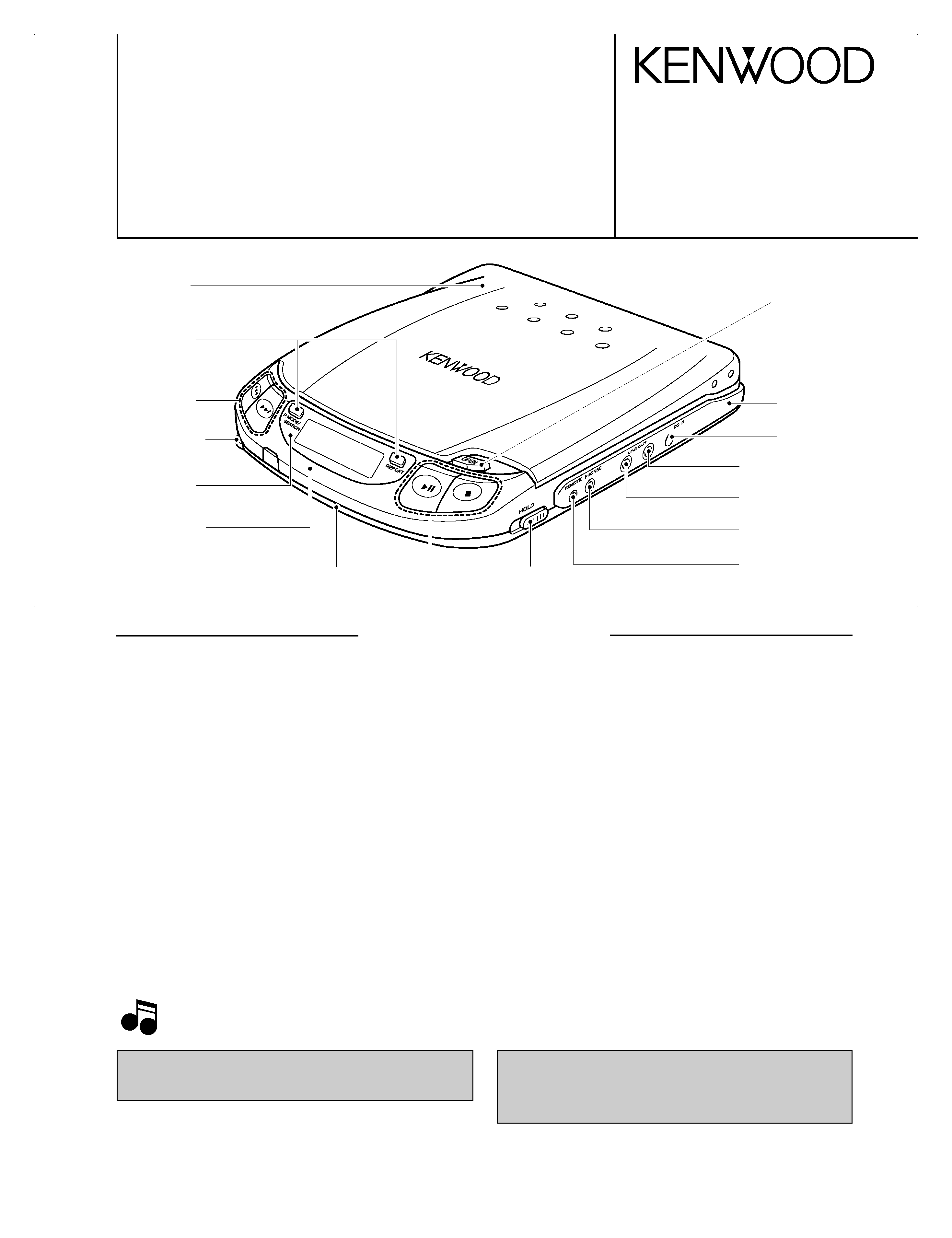
Front glass
(B10-2388-04)
Plastic cabinet *
(A02-)
Chassis
(A10-3391-01)
DC jack
(E03-0355-05)
Cover Assy *
(F07-)
Knob
(K29-6787-04)
Knob
(K29-6785-03)
Knob
(K29-6783-03)
Knob
(K29-6789-04)
Variable resistor
(R31-0090-05)
Miniature phone jack *
(E11-)
Ecctric circuit module
(W02-2527-05)
Miniature phone jack
(E11-0371-05)
Miniature phone jack
(E11-0278-05)
Escutcheon *
(B07-)
Knob
(K29-6788-03)
DPC-781/782/981(K)1P(98.4.2423:08 y[W 2
DPC-781/782/981
2
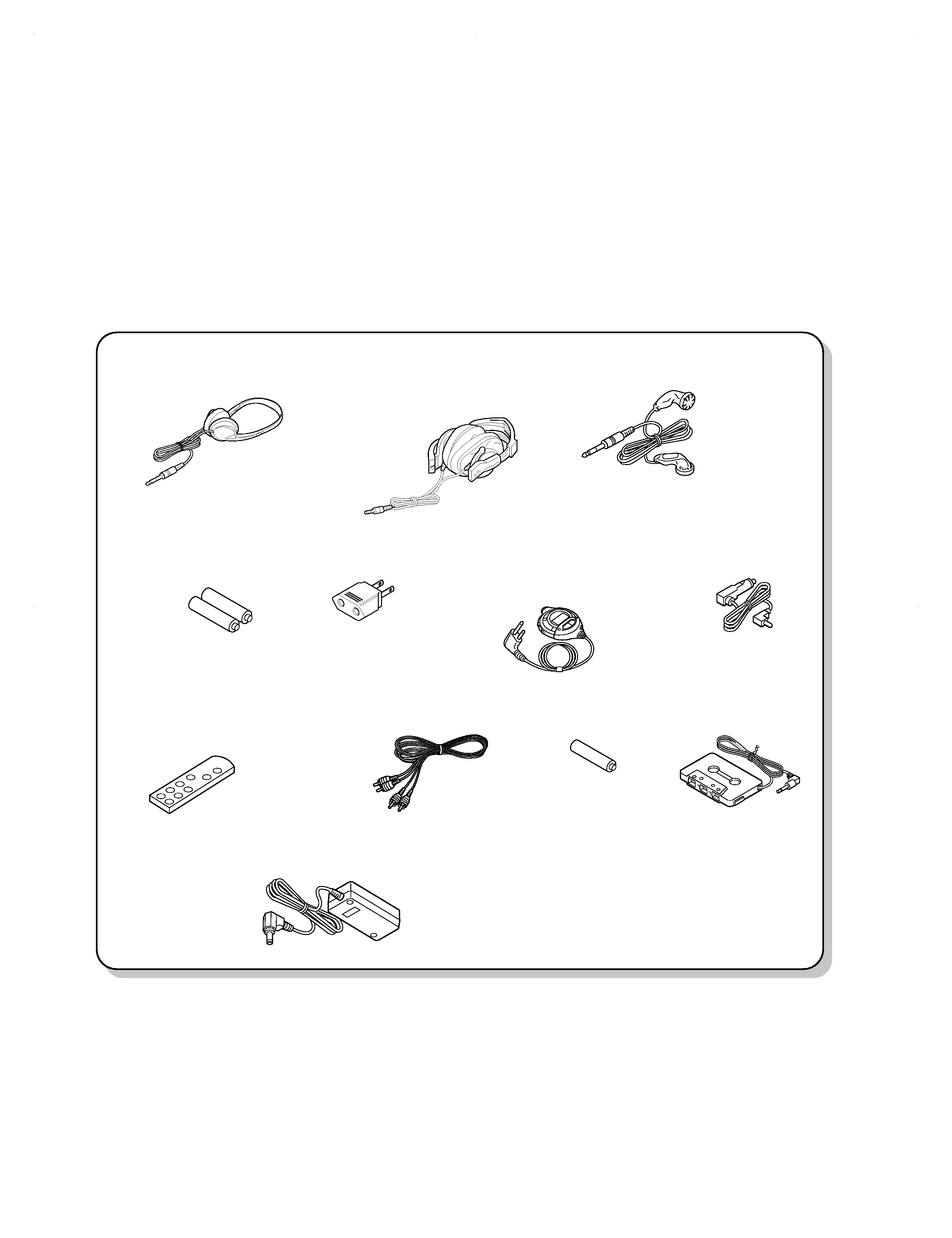
CONTENTS/ACCESSORIES
Stereo headphone (1)
(W01-0923-05) DPC-981 M type
DPC-781 M type
DPC-782 X type
Stereo headphone (1)
(W01-0924-05) DPC-782
Cassette adaptor (1)
(W01-0922-05) DPC-782
Car battery adaptor (1)
(W01-0921-05) DPC-782
AC plug adaptor (1)
(E03-0115-05) M type
Rechargeable battery (2)
option : NB -130
(W09-1237-05)
Remote control (1)
(A70-1171-05) DPC-981 M type
DPC-781 M type
(A70-1190-05) DPC-782 X type
AC adaptor (1)
(W08-0658-05) E type
(W08-0659-05) T type
(W08-0660-05) X type
(W08-0667-05) M type
(W09-1251-05) K, P type
Remote controller assy (1)
(A70-1037-05) DPC-782
DPC-981 K,P type
Audio cord
(E30-2782-05) DPC981 T,E type
Battery (1)
DPC-981
Stereo headphone (1)
(W01-0946-05) DPC-981 M type
(W01-0947-05) DPC-981 K,P type
(W01-0954-05) DPC-981 T,E type
SPECIFICATIONS .........................................Top cover
CONTENTS/ACCESSORIES ......................................2
ADJUSTMENT .............................................................3
PC BOARD ................................................................. 5
SCHEMATIC DIAGRAM ............................................. 7
EXPLODED VIEW .....................................................13
PARTS LIST...............................................................15
Accessories
CONTENTS
AAA
()
DPC-781/782/981(K)1P(98.4.2423:08 y[W 3
DPC-781/782/981
3
ADJUSTMENT
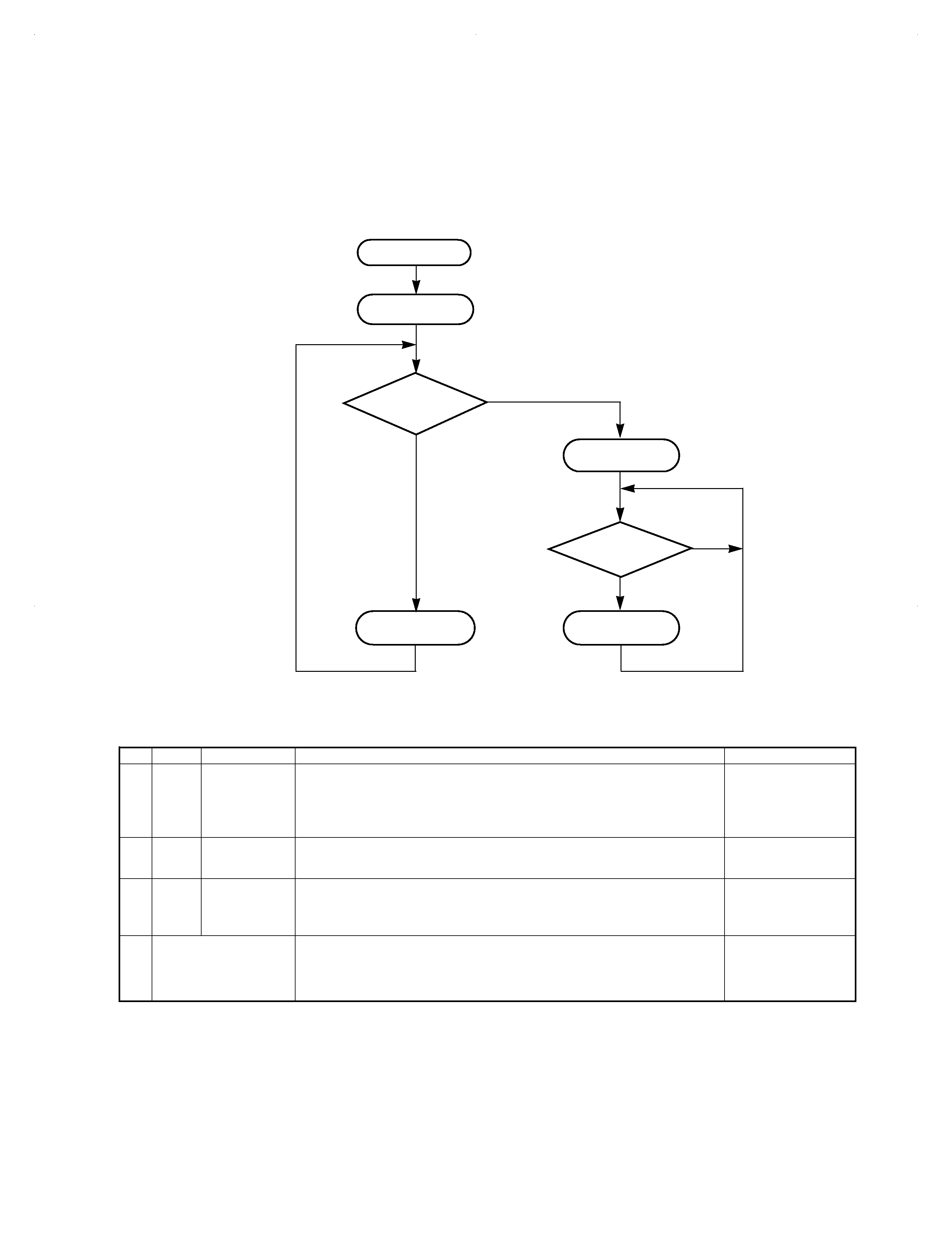
1. Test Mode
1-1 Setting the test mode
This model can be set to the test mode by shorting
the test-land of the X32 board.
START
Turn on lid
switch
Is test land
shorted?
Test mode pro-
cessing
Is key pushed?
Track No. "01"
is displayed.
TEST MODE
YES
NO
NO
See following table.
Normal operation
No.
Mode
Key Name
Function
TRACK No. display
1
05
PLAY/PAUSE
(
6)
1. Focus servo.....................................................................................................ON
2. Tracking servo.................................................................................................ON
3. Feed servo ......................................................................................................ON
Absolute time at position of limit SW is displayed in time area, then play is started.
05
After 1, 2 and 3 are fin-
ished, track No. played
currently and its play
time are indicated.
2
03
UP
(
¢)
1. Focus servo.....................................................................................................ON
2. Tracking servo...............................................................................................OFF
3. Feed servo ....................................................................................................OFF
03
3
01
STOP
(
7)
1. Focus servo...................................................................................................OFF
2. Tracking servo...............................................................................................OFF
3. Feed servo ....................................................................................................OFF
( Test mode can be can celled while pressing the STOP (
7) Key in 01 mode.
01
4
While pressing the
P. MODE/SEARCH Key,
turn the AC ON
All LCD is turned ON for 2 seconds.
ó
All LCD is turned OFF for 2 seconds.
ó
Returned to normal mode.
--
1-2 Key and functions avild in test mode
DPC-781/782/981(K)1P(98.4.2423:08 y[W 6
DPC-781/782/981
4
ADJUSTMENT
No.
2
1
LASER
POWER
Apply the sensor
section of optical
power meter on
the
pickup lens.
Short the test land. Confirm
that the display is
"
".
Press FF Key and confirm
that the display is 03.
On the power from
0.08 to 0.15 mW,
when the diffraction
grating is correctly
aligned with the RF
level of 1.0 Vp-p or
more.
3
4
5
ITEM
FOCUS
ERROR
TRACKING
ERROR
FOCUS
GAIN
TRACKING
GAIN
INPUT
SETTING
Test disc
KTD-03
Test disc
KTD-03
Test disc
KTD-03 Apply
signal of
1.0kHz,
0.05Vrms
between
Check-land F1
and F2.
Test disc
KTD-03 Apply
signal of
1.0kHz,
0.05Vrms
between
Check-land T1
and T2.
OUTPUT
SETTING
Connect an oscillo-
scope as follows.
CH1:RF
(Check-land RF)
CH2:T1
(Check-land TE1)
Press the FF key.
Confirm that the display is
"
".
Connect a LPF
between Check-
land F1 and F2 to
which connect an
oscilloscope or AC
voltmeters.
Connect a LPF
between Check-
land T1 and T2 to
which connect an
oscilloscope or AC
voltmeters.
Connect an oscillo-
scope as follows.
CH1:RF
(Check-land RF)
CH2:T1
(Check-land TE1)
PLAYER
SETTING
Press the PLAY key .
Confirm that the display is
"05".
Press the PLAY key .
Confirm that the display is
"05".
Press the PLAY key .
Confirm that the display is
"05".
ALIGNMENT
POINT
TE
BALANCE
VR5
FOCUS
GAIN
VR4
TRACKING
GAIN
VR6
FE
BALANCE
VR3
ALIGN FOR
Optimum eye pattern
Symmetry between
upper and lower
Two VTVMs should
read the same
value.
Two VTVMs should
read the same
value.
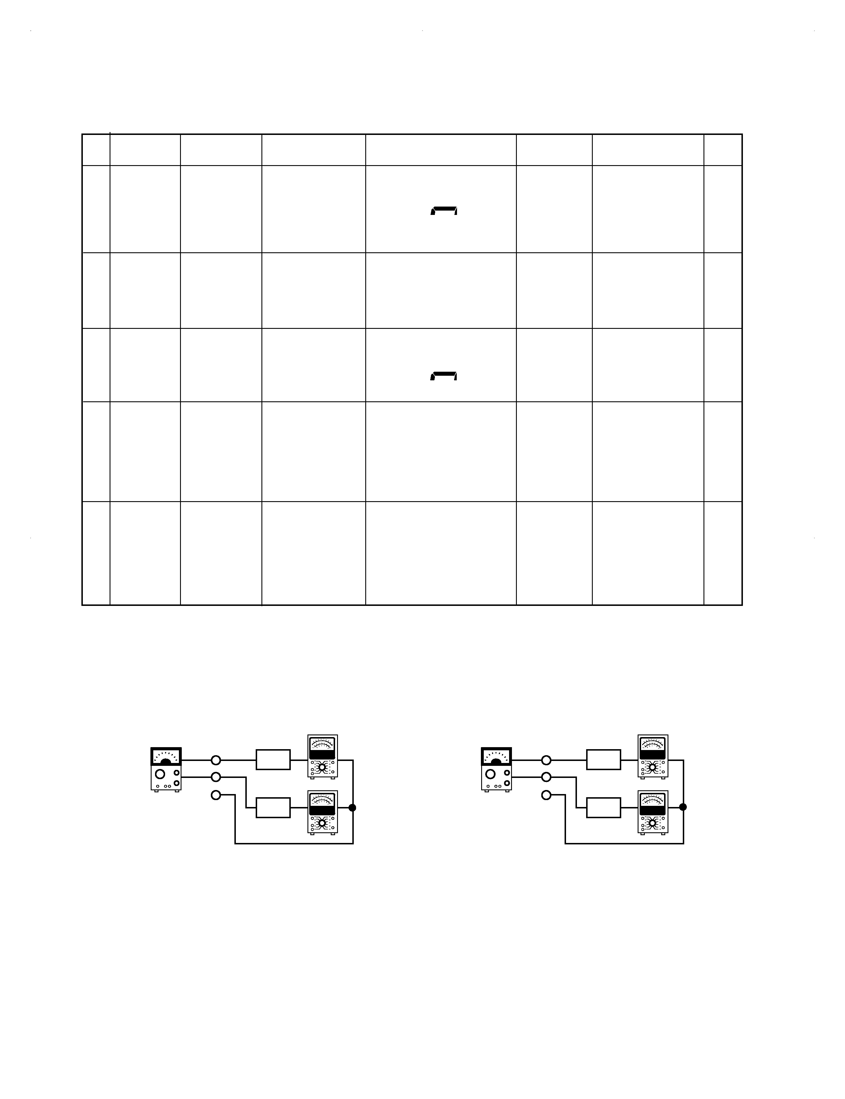
FIG.
(d)
(e)
L.P.F
L.P.F
F1
F2
AC voltmeter
VC
1.0kHz
0.05Vrms
L.P.F
L.P.F
T1
T2
AC voltmeter
VC
1.0kHz
0.05Vrms
Note: Test DISC KTD-03, TCD-783 or equivalent
LPF : Around 47k
+ 390 pF or so.
Step 1~5 are in Test Mode.
(d) Focus Gain
Two VTVMs should read the same
value.
(e) Tracking Gain
Two VTVMs should read the same
value.
DPC-781/782/981(K)1P(98.4.2423:08 y[W 7
A
C
E
BD
2
1
3
5
7
4
6
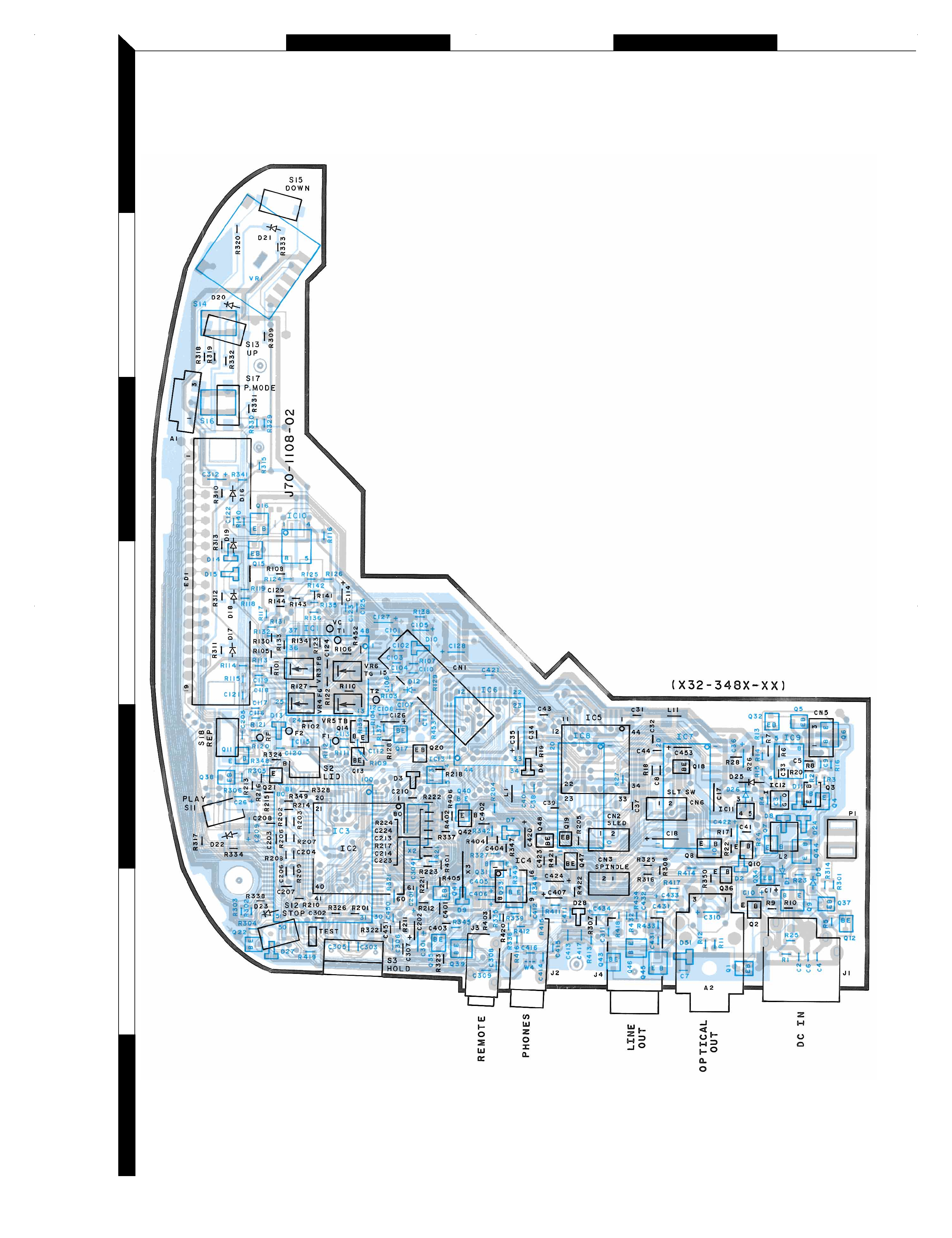
PC BOARD(Component side view)
Refer to the schematic diagram for the value of resistors and capacitors.
5
DPC-781/782(K)pcb 98.3.204:10PM y[W 1