
CD PLAYER
DP-5090
DP-4090
INSTRUCTION MANUAL
KENWOOD CORPORATION
DIGITAL AUDIO
COMPACT
B60-3043-00 MA ( T, M )
I D
98/12 11 10 9 8 7 6 5 4 3 2 1 97/12 11 10 9 8 7 6 5
This instruction manual is used for two models.
Model availability and features (functions) may differ
depending on the country and sales area.
DP-5090/4090 (En)
2 Before applying power
Caution : Read this section carefully to ensure safe operation.
Units are designed for operation as follows.
U.S.A. and Canada ................................................................ AC 120 V only
Australia .................................................................................. AC 240 V only
Europe and U.K. ..................................................................... AC 230 V only
China ......................................................................................... AC 220 V only
*Other countries ............................ AC 110-120 / 220-240 V switchable
The marking is located on the rear panel and says that the compo-
nent uses laser beams that have been classified as Class 1. It means
that the unit is utilizing laser beams that are of a weaker class. There
is no danger of hazardous radiation outside the unit.
CLASS 1
LASER PRODUCT
The marking of products using lasers
(Except for some areas)
REQUIREMENT BY NEDERLAND GAZETTE
Batteries are supplied with this product. When
they empty, you should not throw away. Instead,
hand them in as small chemical waste.
Introduction
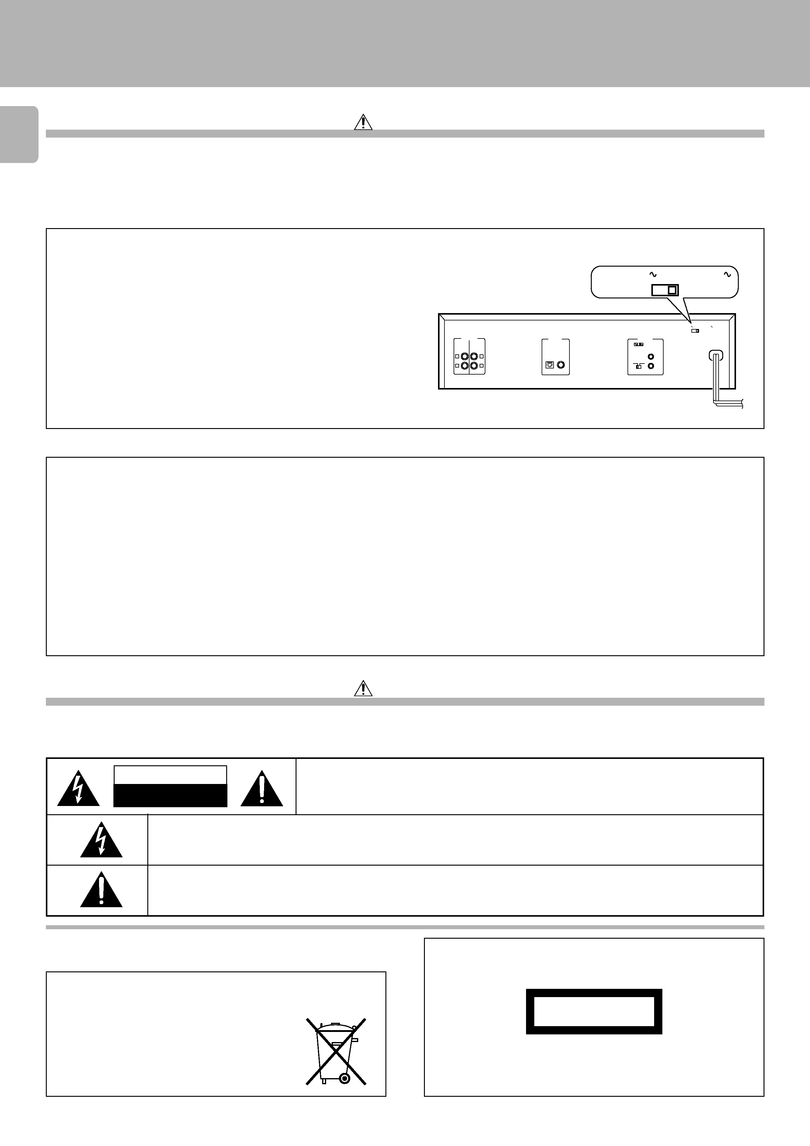
*AC voltage selection
The AC voltage selector switch on the rear panel is set to the voltage that
prevails in the area to which the unit is shipped. Before connecting the
power cord to your AC outlet, make sure that the setting position of this
switch matches your line voltage. If not, it must be set to your voltage in
accordance with the following direction.
Move switch lever to match your line voltage
with a small screwdriver or other pointed tool.
AC voltage selector switch
L
R
L
R
LINE 1
LINE 2
OUTPUT
DIGITAL
OUTPUT
SYSTEM
CONTROL
OPTICAL COAXIAL
SL16 XS 8
AC110-220V
2 3AC220-240V
AC110-220V
23AC220-240V
Note:
Our warranty does not cover damage caused by excessive line volt-
age due to improper setting of the AC voltage selector switch.
For the United Kingdom
Factory fitted moulded mains plug
1. The mains plug contains a fuse. For replacement, use only a 13-Amp ASTA-approved (BS1362) fuse.
2. The fuse cover must be refitted when replacing the fuse in the moulded plug.
3. Do not cut off the mains plug from this equipment. If the plug fitted is not suitable for the power points in your home or the cable is too short to reach
a power point, then obtain an appropriate safety approved extension lead or adapter, or consult your dealer.
If nonetheless the mains plug is cut off, remove the fuse and dispose of the plug immediately, to avoid a possible shock hazard by inadvertent
connection to the mains supply.
IMPORTANT
The wires in the mains lead are coloured in accordance with the following code:
Blue
: Neutral
Brown : Live
Do not connect those leads to the earth terminal of a three-pin plug.
WARNING : TO PREVENT FIRE OR ELECTRIC SHOCK, DO NOT EXPOSE THIS
APPLIANCE TO RAIN OR MOISTURE.
Safety precautions
THE LIGHTNING FLASH WITH ARROWHEAD SYMBOL, WITHIN AN EQUILATERAL TRIANGLE, IS INTENDED TO ALERT
THE USER TO THE PRESENCE OF UNINSULATED "DANGEROUS VOLTAGE" WITHIN THE PRODUCT'S ENCLOSURE
THAT MAY BE OF SUFFICIENT MAGNITUDE TO CONSTITUTE A RISK OF ELECTRIC SHOCK TO PERSONS.
Caution : Read this section carefully to ensure safe operation.
THE EXCLAMATION POINT WITHIN AN EQUILATERAL TRIANGLE IS INTENDED TO ALERT THE USER TO THE
PRESENCE OF IMPORTANT OPERATING AND MAINTENANCE (SERVICING) INSTRUCTIONS IN THE LITERATURE
ACCOMPANYING THE APPLIANCE.
CAUTION
RISK OF ELECTRIC SHOCK
DO NOT OPEN
CAUTION: TO REDUCE THE RISK OF ELECTRIC SHOCK, DO NOT REMOVE COVER (OR
BACK). NO USER-SERVICEABLE PARTS INSIDE, REFER SERVICING TO QUALIFIED
SERVICE PERSONNEL.
3
DP-5090/4090 (En)
Unpacking
Unpack the unit carefully and make sure that all accessories are put aside so they will not be lost.
Examine the unit for any possibility of shipping damage. If your unit is damaged or fails to operate, notify your dealer immediately. If your unit was shipped
to you directly, notify the shipping company without delay. Only the consignee (the person or company receiving the unit) can file a claim against the carrier
for shipping damage.
We recommend that you retain the original carton and packing materials for use should you transport or ship the unit in the future.
Keep this manual handy for future reference.
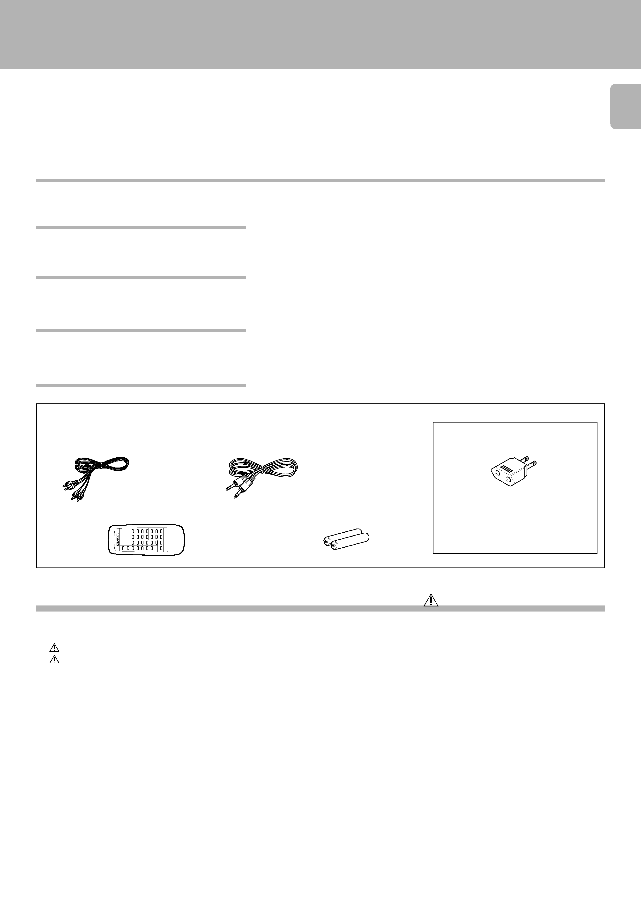
Accessories
Audio cord ........................ (1)
System control cord ............ (1)
Remote control unit ......... (1)
Batteries (R6/AA) .............. (2)
REMOTE
CONTROL
UNIT
RC-P0505
AC plug adaptor .............. (1)
Use to adapt the plug on the power cord
to the shape of the wall outlet.
(Accessory only for regions where use is
necessary.)
Contents
Caution: Read the pages marked
carefully to ensure safe operation.
Displaying all the text information (ALL INFO.) ............. 13
Programmed play (PGM mode) ................................ 14
To check or change the programmed tracks .................. 15
To add a track to the program ......................................... 15
To clear tracks from the program .................................... 15
Repeated playback .................................................... 16
To repeat only the programmed tracks ........................... 16
To repeat the entire disc ................................................... 16
Playback in random order (Random playback) ....... 17
Editing ......................................................................... 18
To check the edited contents ........................................... 19
Playing or recording the edited contents ....................... 19
To clear the edited contents ............................................. 19
Peak search ........................................................................ 19
Timer operations ........................................................ 20
In case of difficulty ..................................................... 21
Specifications ............................................................. 23
Introduction .................................................................. 2
Before applying power ................................................ 2
Safety precautions ....................................................... 2
Special features ................................................................... 3
System connections .................................................... 4
To use the headphone ......................................................... 5
Maintenance ................................................................. 7
Controls and indicators ............................................... 8
Operation of remote control unit ............................... 9
Normal play (TRACK mode) ...................................... 10
Playing tracks in order from track No.1 .......................... 10
Playback from desired track ............................................. 11
Skipping tracks .................................................................. 11
Searching ........................................................................... 11
Searching for tracks by title (TITLE SEARCH) ......... 12
Displays ...................................................................... 13
Time display on CD player (TIME DISPLAY) .................... 13
Selecting the text information display
(TEXT DISPLAY) ................................................................. 13
¶ The text information (disc title, track titles, names of the artists, songwriters, composers,
etc.) recorded on the CDs can be easily called and displayed in alphanumerics. (Some
Japanese words and text may not be displayed.)
@#
¶ D.R.I.V.E. (Dynamic Resolution Intensive Vector Enhancement) IC is built in for drastic re-
duction of distortion at small signal level.
¶ High-performance new D/A converter achieving a 24-bit resolution. (DP-5090 only)
¶ CD peak search for setting the recording level that does not cause distortion.
(
¶ Edit function for rearranging tracks according to the tape length so that no music is inter-
rupted in the middle.
*
¶ Auto space function.
%
¶ Easy operation functions allow systematic operation with other KENWOOD components
connected through the system control connection.
6
Special features
CD-TEXT support
Advanced technologies incorporated in pursuit
of improved sound quality and stability
Convenient features for dubbing CD onto tape
Easy operation functions
DP-5090/4090 (En)
4
System connections
Caution:
Do not plug in the power lead until all connections are com-
pleted.
Malfunction of microcomputer
If operation is not possible or erroneous display appears even
though all connections have been made properly, reset the
microcomputer referring to "In case of difficulty".
¡
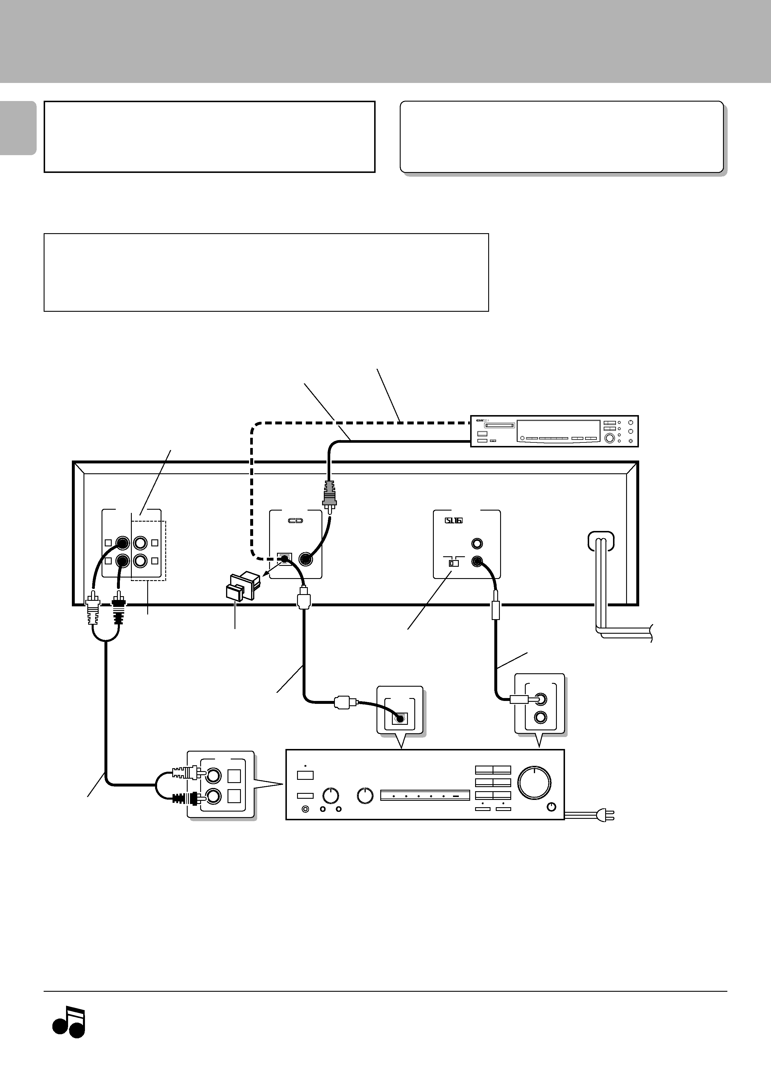
Make connections as shown below.
When connecting the related system components, refer also to the
instruction manuals of the related components.
Caution regarding placement
To maintain proper ventilation, be sure to leave a space around the unit (from the largest outer
dimensions including projections) equal to, or greater than, shown below.
Left and right panels: 10 cm
Rear panel: 10 cm
SYSTEM
CONTROL
L
R
CD
L
R
L
R
LINE 1
LINE 2
OUTPUT
DIGITAL
OUTPUT
SYSTEM
CONTROL
OPTICAL COAXIAL
SL16 XS 8
AC110-220V
2 3AC220-240V
DIGITAL
INPUT
OPTICAL
TEXT
(DP-5090 only)
LINE 1 and LINE 2 output are the same
pair of signals. Use these jacks to connect
the unit to other system components.
75
coaxial cable with RCA PIN.
(Commercially-available)
Commercially-available
optical fiber cable
DIGITAL INPUT
(COAXIAL)
(OPTICAL)
Digital component (MD, DAT, etc.)
Commercially-available
optical fiber cable
Remove the protection cap
when using the DIGITAL
OUTPUT (OPTICAL) jack.
Audio cord
SL 16/XS8
switch
6
System control cord
Digital amplifier
(or ordinary amplifier,
receiver, etc.)
To wall AC outlet
1. Connect all cords firmly. If connections are loose there could be loss of sound or noise produced.
2. When plugging and unplugging connection cords, be sure to first remove the power cord from the AC outlet. Plugging/unplugging
connection cords without removal of the power cord can cause malfunctions or damage to the unit.
Notes
Notes
(Except for DP-4090)
To AC outlet
5
DP-5090/4090 (En)
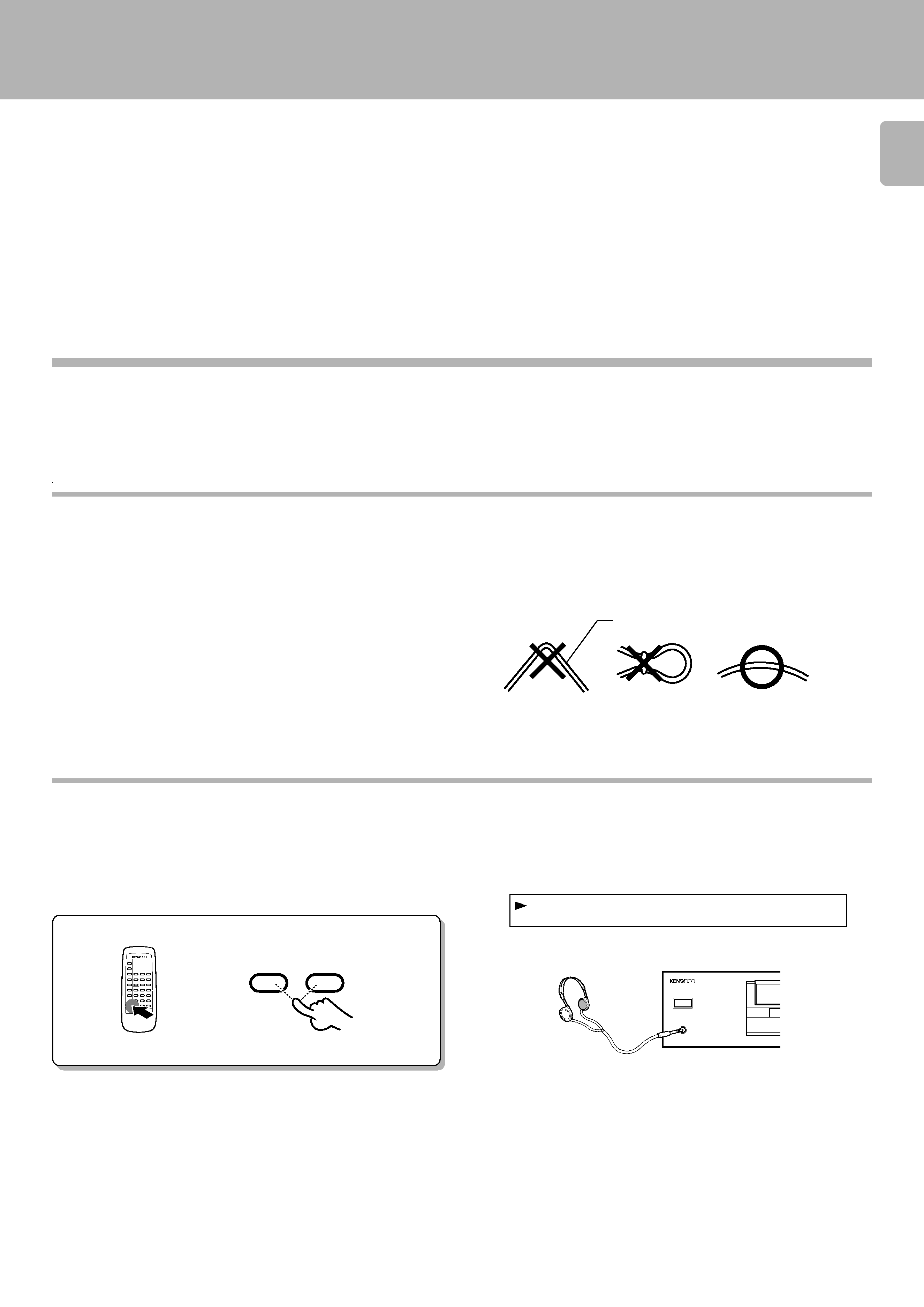
Adjusting the output levels of the output jacks
and headphone output
The OUTPUT level (UP/DOWN) keys of the remote control unit can
adjust the output levels from the LINE/OUT and PHONES jacks of
the unit.
REMOTE CONTROL UNIT
RC-P0505
OUTPUT
DOWN
UP
To use the headphone
Connect a stereo headphone to the PHONES jack of the CD player.
Adjust the sound volume using the remote control unit.
OT
UU
PT
1
-d
2B
Output level
PHONES
POWER
-ON OFF
COMPACT DISC PLAYER DP-5090
÷ It is not favorable for the sound quality to decrease the output level from
this unit too much. Use these keys for coordination with other line
levels.
÷ Adjusting the headphone output level also changes the LINE/OUT
level. Do not adjust the output level from this unit particularly during
recording.
Connection to a general-use amplifier
Use the provided audio cords to connect the OUTPUT jacks of this
unit to the CD input jacks (or AUX jacks) of the amplifier.
Connection to digital amplifier or MD
Connect the DIGITAL OUTPUT (OPTICAL or COAXIAL) jack to the
digital input jack of the amplifier, DAT recorder, MD recorder, etc.,
using an optical fiber cable or coaxial cable which are commercially
available in audio stores.
÷ When using an optical fiber cable to connect this unit to a digital
amplifier, insert the plug straight into the jack until a snap sound is
heard.
÷ Be careful not to bend, coil, or bundle the optical fiber cable.
÷ Optical fiber cables available on the market may not always be able to
be used with this player. If your cord cannot be used with this unit,
consult the store from which you purchased the cord or your nearest
dealer.
Optical fiber cable