In compliance with Federal Regulations, following are
reproductions of labels on, or inside the product relating to
laser product safety,
KENWOOD-Corp. certifies this equipment conforms to
DHHS Regulation No.21 CFR 1040.10, Chapter 1,
Subchapter J.
DANGER : Laser radiation when open and interlock
defeated.
AVOID DIRECT EXPOSURE TO BEAM.
Illustration is DMF-9020.
Refer to parts list on page 29.
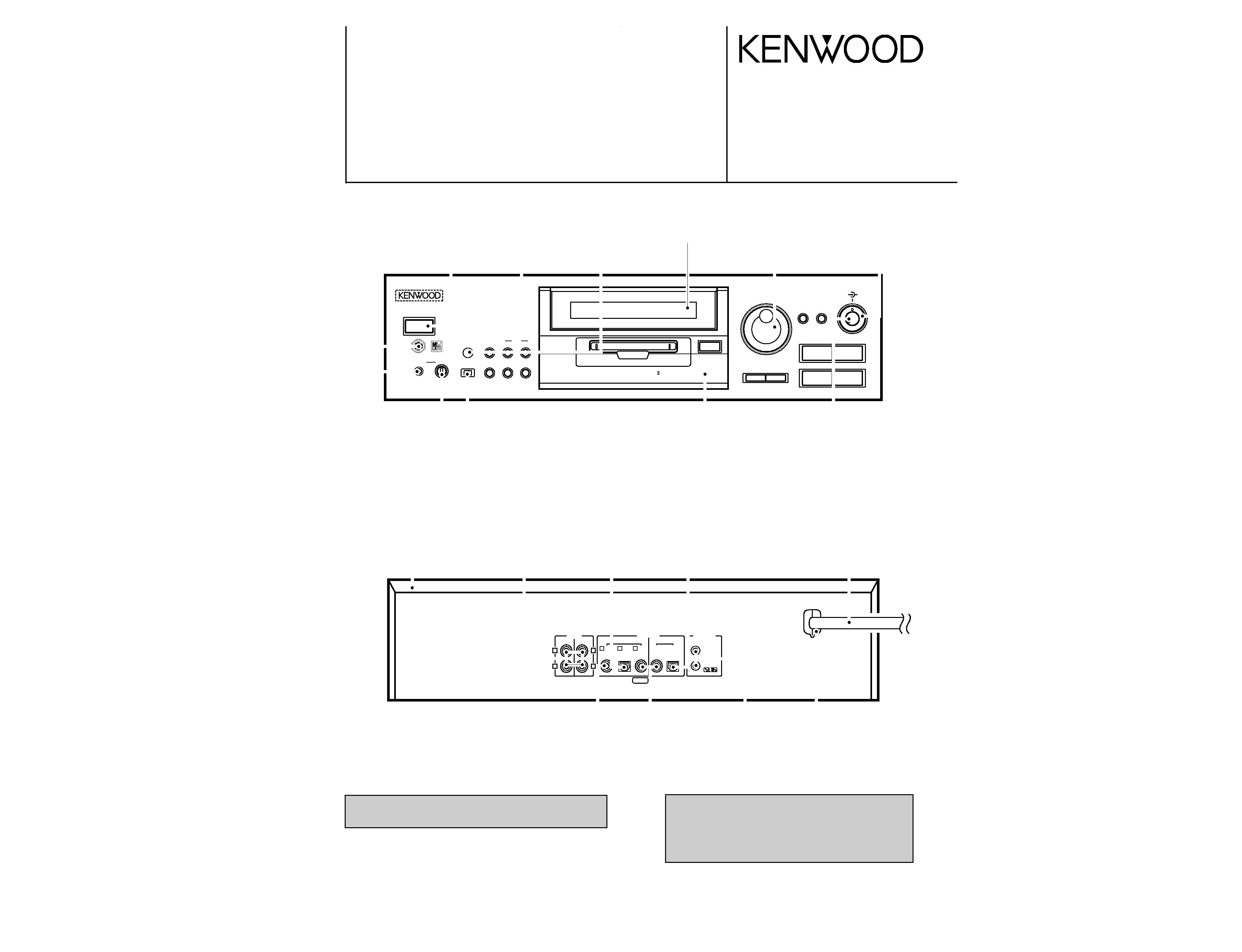
STEREO MINIDISC RECORDER
DMF-9020/9020(S)
MD-2070
SERVICE MANUAL
©1998-11/B51-5495-00 (K/K) 2945
EDIT/
SPACE
FADE/
DELETE
INPUT
MONITOR
REC INPUT
STEREO MINIDISC RECORD ER
TIMER
PHONES
KEYBOARD
LEVEL
MIN
MAX
OFF
PLAY
REC
SEARCH
TITLE
DISC LOADING MECHANISM
24 bit Rec. & Play D.R.I.V.E.
0
1
¡
4
¢
8
7
3
ENTER
/TIME DISPLAY
U P
DOWN
PUSH SET
SEARCH
JOG DIAL
REC LEVEL
REC BALANCE
MIN
L
R
MAX
REC MODE
/CHARAC.
POWER
- O N OFF
TEXT
R
L
SYSTEM
CONTROL
PLAY
OUT
OPT.
COAX.
REC
IN
3 COAX.
1 COAX.
2 OPT.
D I G I T A L
L I N E
PLAY
OUT
REC
I N
R
L
Knob
(K27-2178-04)
Knob
(K29-6700-03)
Knob
(K29-6692-04)
Front glass
(B10-2362-04)
Phone jack
(E63-0190-05)
Metallic cabinet
(A01-3449-01)
Phono jack
(E63-1066-05)
Oscillating module
(W02-1114-05)
AC Power cord *
(E30-)
Optic receiving module
(W02-1181-05)
Phono jack
(E63-1059-05)
Phono jack
(E63-0174-05)
Miniature phone jack
(E11-0188-05)
Power cord bushing
(J42-0083-05)
Knob
(K29-6697-04)
Color filter
(B11-0237-14)
Dressing panel ass'y
(A21-3756-03)
Knob
(K29-6695-14)
Knob
(K29-3741-04)
KENWOOD badge
(B43-0302-04)
Phono jack
(E63-1066-05)
DMF-9020(K)INT1,1P( 98.11.265:23PM y[W 2
Caution on condensation
Condensation (of dew) may occur inside the unit when there is a great
difference in temperature between this unit and the outside.
This unit may not function properly if condensation occurs. In this
case, leave the unit for a few hours with the power left ON, and
restart the operation after the condensation has dried up.
Be specially cautious against condensation in a follow-
ing circumstance:
When this unit is carried from a place to another across a large
difference in temperature, when the humidity in the room where this
unit is installed increases, etc.
Operation to reset
The microprocessor may fall into malfunction (impossibility to operate
erroneous display, etc.) when the power cord is unplugged while power
is ON or due to an external factor. In this case, execute the following
procedure to reset the microprocessor and return it to normal condition.
With the POWER key left to ON, unplug the power cord
from the power outlet then, while holding the eject (
0)
key depressed, plug the power cord again.
÷ Please note that resetting the microprocessor clears the contents
stored in, it returns the microprocessor to the condition when it left
the factory.
Before transporting or moving this unit, carry out the
following operations.
1. Set the POWER key to ON without loading a Mini Disc.
÷ Check that no disc is present in the unit.
2. Wait a few seconds and verify that the display shown
appears.
3. Set the POWER key to OFF.
Note related to transportation and
movement
N O
D I S C
DMF-9020/9020(S)/MD-2070
2
CONTENTS/ACCESSORIES/CAUTIONS
CONTENTS/ACCESSORIES/CAUTIONS ...................2
CONTROLS .................................................................3
BLOCK DIAGRAM .......................................................5
CIRCUIT DESCRIPTION .............................................6
PC BOARD ................................................................. 9
SCHEMATIC DIAGRAM ........................................... 13
EXPLODED VIEW .....................................................27
PARTS LIST...............................................................29
SPECIFICATIONS .......................................Back cover
CONTENTS
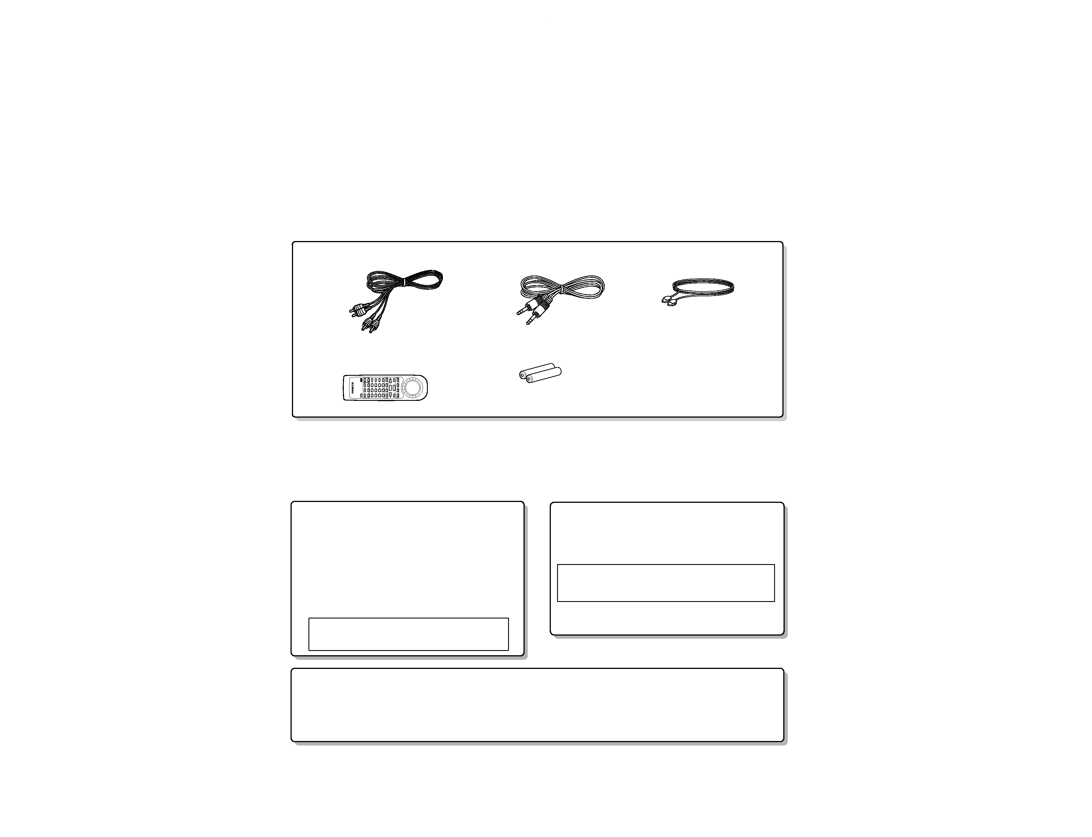
Remote control unit (1)
RC-M0905
(A70-1255-05)
Battery cover (A09-1106-08)
Batteries (2)
Audio
(E30-0505-05)
(E30-2733-05)
(B19-1529-05)
cord (2)
System control cord (1)
Optical fiber cable (1)
Cautions
Accessories
DMF-9020(K)INT1,1P( 98.11.265:24PM y[W 3
DMF-9020/9020(S)/MD-2070
3
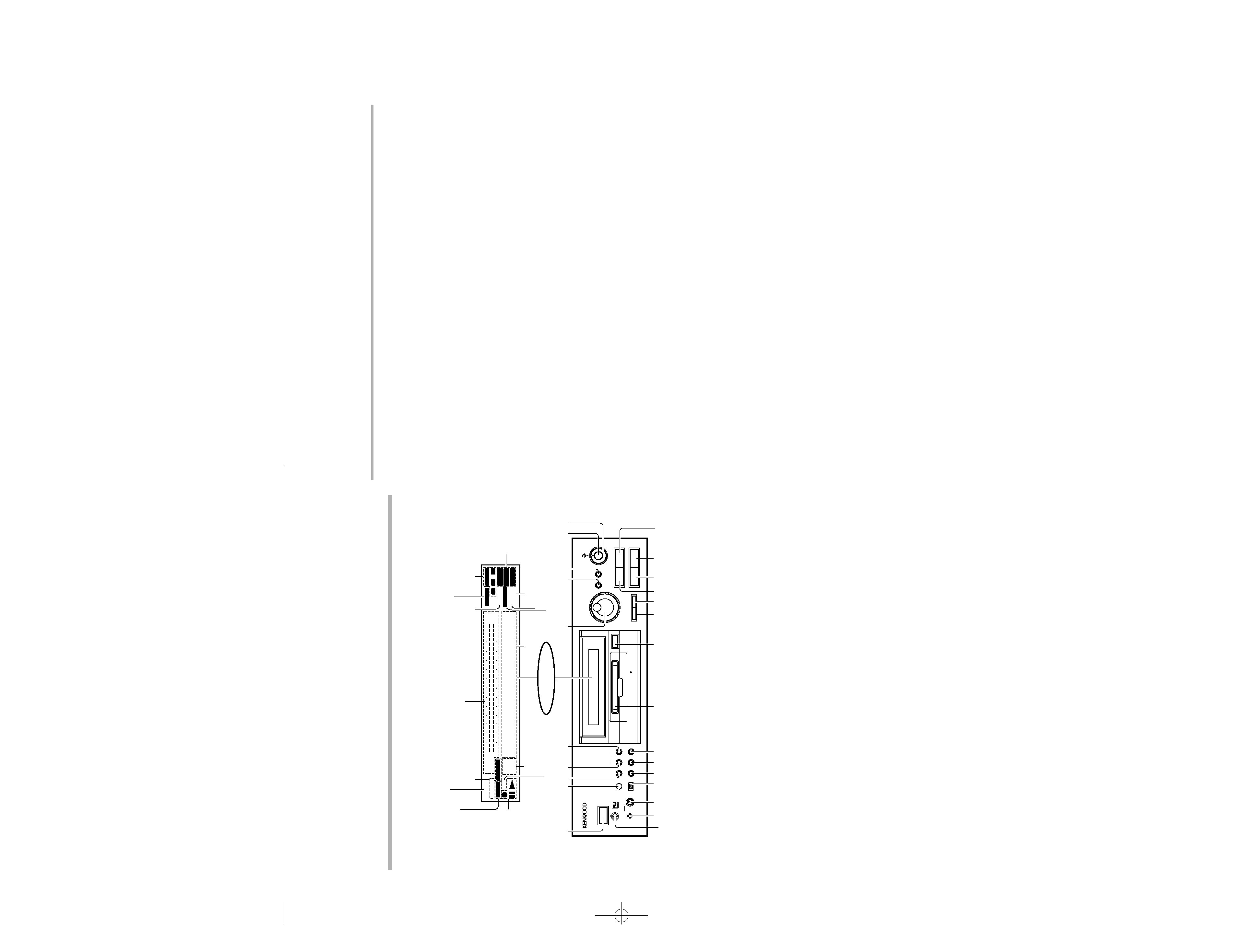
CONTROLS
Description of main unit keys
1POWER key
: Press to turn the unit ON and OFF.
: The unit may enter the standby mode when the POWER key
is pressed to turn it ON. This is because the unit holds the
memory that it has been put to the standby mode by the
remote control unit in the last operation.
2Remote control sensor
3EDIT/SPACE key
EDIT
: Press to switch the editing mode ON/OFF.
SPACE
: Press to insert a blank space character during the title input
operation.
4TITLE INPUT key
: Press to switch the title input mode ON/OFF.
5TITLE SEARCH key
: Press to switch the title search mode ON/OFF.
: During title editing, press to switch the title change input
mode between the "overwrite mode" and "insert mode".
6JOG DIAL
Skip down (
4)/ Skip up(¢) knob
: During playback, rotate to skip tracks.
: Before starting recording in record mode, rotate to select the
recording setting adjustment mode.
: During title search, rotate to select a track number.
: During title input, rotate to select a track number or a
character.
: During editing, rotate to select the editing mode or a track
number.
PUSH SET knob
: For use in setting the editing result and input title in memory.
: When pressed in the recording pause mode, the MEMORY
REC function is set and recording starts from the sound
approximately 6 seconds before the current sound.
7REC MODE/CHARAC. (Character) key
REC MODE
: Press to switch the recording setting adjustment modes
(record modes) ON/OFF.
CHARAC.
: Press to select a character group during the title input
operation.
8ENTER/TIME DISPLAY key
ENTER
: For use in executing the editing and title input operations.
TIME DISPLAY
: Press to switch the time and title display.
9REC LEVEL knob
: Rotate to adjust the analog recording level.
0REC BALANCE knob
: Rotate to adjust the analog recording balance.
!Keyboard connector
: Connect an IBM PC compatible keyboard (optional) here.
@PHONES jack
: Connect stereo headphones (optional) here.
#PHONES LEVEL knob
: Rotate to adjust the volume of the headphones.
$ TIMER switch
: This switch is used in timer playback and timer recording.
% REC INPUT key
: Press to switch the recording input line between digital
(optical/coaxial), analog and monaural.
^ MONITOR key
: Press to monitor the sound being input from the source
while the unit is in stop mode.
& FADE/DELETE key
FADE
: Press to switch the fade mode ON/OFF.
DELETE
: During title editing, press to delete a character. During track
editing, press to delete a track.
* Mini Disc insertion slot
: When a Mini Disc is inserted while the unit is in the standby
mode, it is turned ON automatically.
( Eject (0) key
: Press to eject the Mini Disc.
) Manual search down (1) key
: This key also functions as the fast reverse key during
playback.
: During an editing mode, press to move the title input
cursor or to scroll the track title display to the left.
¡ Manual search up (¡) key
: This key also functions as the fast forward key during
playback.
: During an editing mode, press to move the title input
cursor or to scroll the track title display to the right.
TMPause (8) key
: Press to let playback or recording pause temporarily.
£Stop (7) key
: Press to stop playback or recording.
¢Play (3) key
: Press to start playback.
Record (¶) key
: Press to start recording.
In stop mode
: When the
¶ key is pressed while a recordable disc is present
in the unit, it enters record-pause mode.
(It enters record-pause mode at the position immediately
after the last existing track.)
In record-pause mode
: When the
¶ key is pressed, the SOUND SYNCHRO REC
standby mode is set.
: In the SOUND SYNCHRO REC standby mode, the set
functions in the same way as in the normal recording pause
mode.
Display / Main unit
EDIT/
SPACE
FADE/
DELETE
INPUT
MONITOR
REC INPUT
STEREO MINIDISC RECORD ER
TIMER
PHONES
KEYBOARD
LEVEL
MIN
MAX
OFF
PLAY
REC
SEARCH
TITLE
DISC LOADING MECHANISM
24 bit Rec. & Play D.R.I.V.E.
0
1
¡
4
¢
8
7
3
ENTER
/TIME DISPLAY
U P
DOWN
PUSH SET
SEARCH
JOG DIAL
REC LEVEL
REC BALANCE
MIN
L
R
MAX
REC MODE
/CHARAC.
@ # $ % ^ &
*
(
) ¡
£ ¢
TM
6
3 4
7 8
0
9
1
2
5
IN
REPEAT
FADE
OVER
OUT
OVER (
-dB)
(
-dB)
MONO
MANUAL
A . PAUSE
R
L
REMAIN
TOTAL
SINGLE
COPY
TITLE
· · · · · · · · · · · ·
¥¥YY
¥¥YY
9
12
7
5
1
3
40
30
21
18
0
15
18
12
9
3
6
40
30
27
24
0
SEARCH
PGM
MONITOR
ANALOG
32kHz
2
1
3
48kHz
44.1kHz
DIGITAL
15
21
!
POWER
- O N OFF
Display
TITLE and SEARCH indicators
MONO indicator
PGM (Program) indicator
COPY indicator
FADE, IN, OUT and peak level indicators
ANALOG input indicator
DIGITAL input 1/2/3 indicators
REPEAT indicator
SINGLE, TOTAL and
REMAIN indicators
Character information
display
A. PAUSE indicator
MANUAL indicator
MONITOR indicator
Operation indicators
¶ REC indicator
8 Pause indicator
3 Play indicator
Sumpling frequency
indicators
DMF-9020(K)
INT1,1P(
98.11.26
5:24
PM
y[W
6
DMF-9020/9020(S)/MD-2070
4
CONTROLS
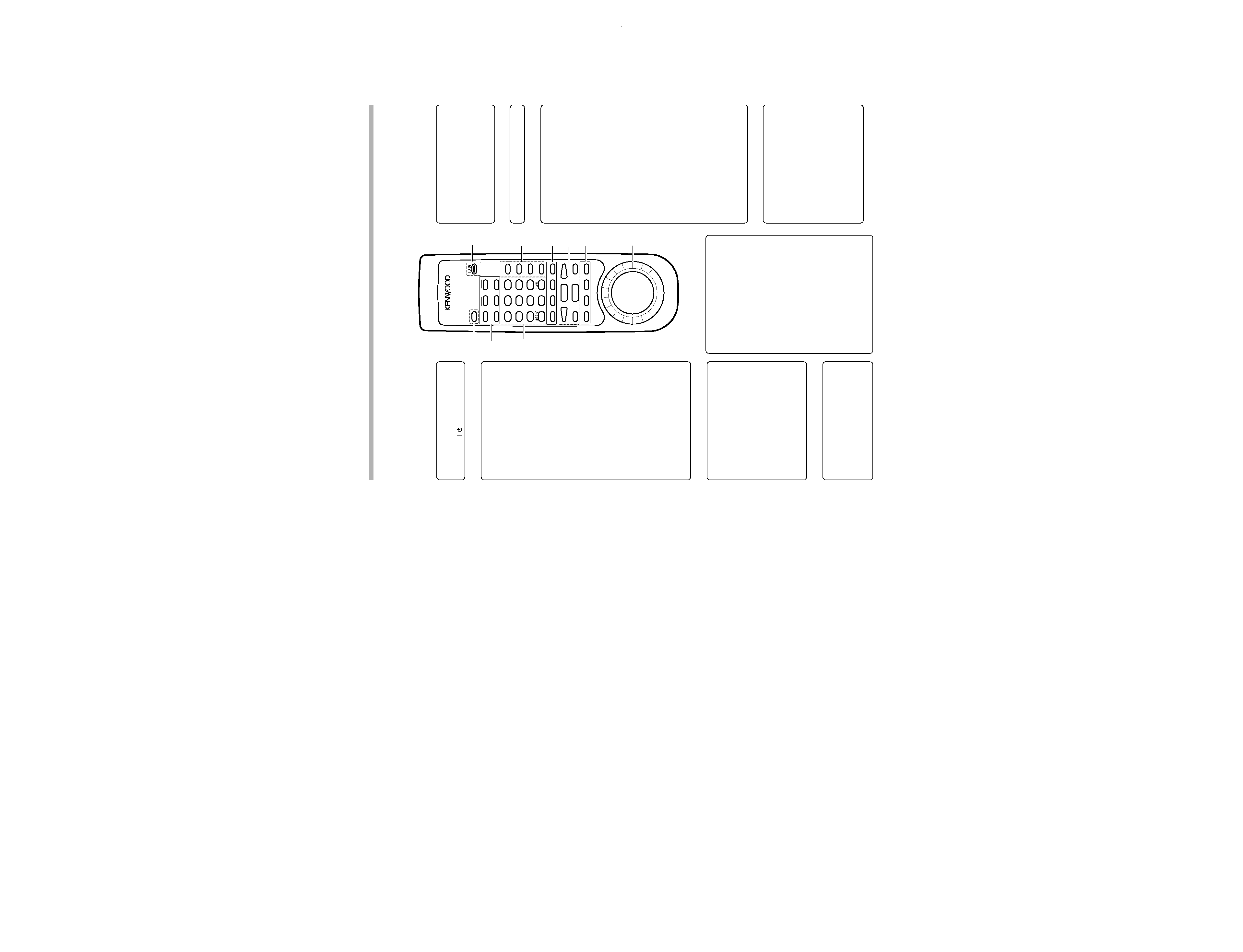
2Character editing keys
TIME DISPLAY key
: Press to switch the time and title display.
CHARA. (Character)/ P.MODE (Play
Mode) key
CHARA.
: Press to select a character group dur-
ing the title input operation.
P.MODE
: Press to initiate the program mode.
DELETE / CLEAR key
DELETE
: During title input, press to delete a
character.
CLEAR
: During editing, press to clear a selected
track number.
: In program mode, press to clear the
program.
SPACE / CHECK key
SPACE
: During title input, press to insert a blank
space character.
CHECK
: In program mode, press to check the
program contents.
7EJECT (0) key
8Editing mode keys
EDIT CANCEL key
: Press to cancel the editing operation.
TITLE INPUT key
: Press to switch the title input mode ON/
OFF.
TITLE SEARCH key
: Press to switch the title search mode
ON/OFF.
: During title editing, press to switch the
title change input mode between the
"overwrite mode" and "insert mode".
SET key
: This key is used in the title assignment or
editing operations.
: When pressed in the recording pause
mode, the MEMORY REC function is set
and recording starts from the sound ap-
proximately 6 seconds before the cur-
rent sound.
ENTER key
: Press to execute editing or enter the
input title in memory.
EDIT key
: Press to switch the editing mode ON/
OFF.
Remote control unit
The remote control unit incorporates the basic operation keys as well as a variety of applied operation keys so that it can be
used in a wide range of purposes.
The keys on the remote control unit with the same names as on the main unit have the same function as the keys
on the main unit.
Model: RC-M0905
Infrared ray system
3MONITOR key
: Press to monitor the sound being input
from the source while the unit is in stop
mode.
METER key
: Press to switch the level meter display
contents.
RANDOM key
: Press to initiate the random play mode.
REPEAT key
: Press to switch the repeat modes for
repeat playback.
1ON/STANDBY key
: Press to turn the unit between ON and
STANDBY ( /
) modes.
5Recording-related keys
REC MODE key
: Press to switch the recording setting ad-
justment modes ON/OFF.
AUTO/MANU. key
: Selects whether the track numbers are
to be marked automatically during re-
cording (AUTO) or to be marked manu-
ally after it (MANUAL).
AUTO PAUSE key
: When this key is pressed, the pause
mode is initiated automatically at the
point where the track number changes
during playback.
: When pressed in the recording or record-
ing standby mode, the AUTO REC PAUSE
mode is turned on.
REC INPUT key
: Press to switch the recording input line
between digital (optical/coaxial), analog
and monaural.
EDIT CANCEL
MONITOR
÷
0
REC MODE
SET
1
GHI
4
PRS
7
+100
METER
AUTO/MANU.
INPUT
ABC
ENTER
2
JKL
5
TUV
8
QZ
0
RANDOM
AUTO PAUSE
SEARCH
DEF
EDIT
3
MNO
6
WXY
9
+10
REPEAT
8
REC INPUT
CHARA.
DELETE
SPACE
TITLE
TMTM/CUR.L
CUR.R/
££
TIME
DISPLAY
POWER
REMOTE CONTROL UNIT
RC-M0905
4
¢
£
7
CLEAR
CHECK
P.MODE
7
8
1
2
3
4
5
6
9
4Basic operation keys
3
: Play key
4 , ¢ : Skip down/up keys
: Record key
7
: Stop key
8
: Pause key
6CURSOR / 1 , ¡ shuttle
CURSOR
: During title input, rotate to move the
cursor.
1 , ¡
: Use this during playback for forward and
reverse search.
9Numeric keys
0-9
: Press when selecting a track number
directly.
+10
: Press when selecting a track number 10
or more.
+100
: Press when selecting a track number
100 or more.
: These keys are also used to select a
character or symbol during title editing.
DMF-9020(K)
INT1,1P(
98.11.26
5:24
PM
y[W
7
DMF-9020/9020(S)/MD-2070
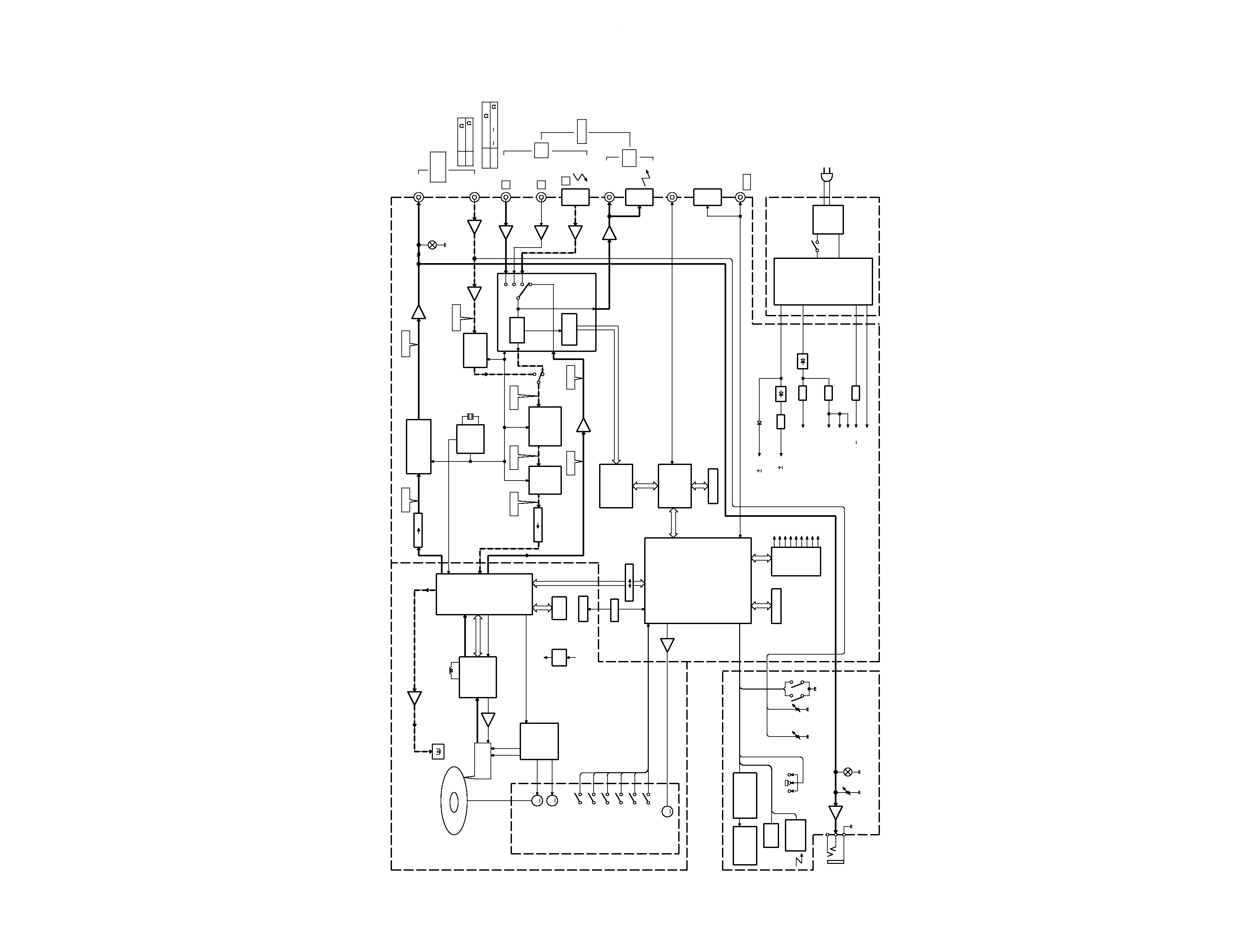
5
BLOCK
DIAGRAM
RF,TE,FE,SE
CONT,BUS
APC REF
I,J,
A,B,C,D,E,F
SPINDLE
FEED
FCS,TRK,SPIN,SLED PWM
AUDIO
SYSTEM
AC
TRK
FCS
-VFL
512fs
256fs
MECHA: MDM-04 (X33-1100-00)
(X25-617X-XX)
(X00)
(X14-4380-00)
MAIN (MECHA.)
u-COM
UPD784215GF533
256K SRAM
IC31
POWER
TRANSFORMER
FILTER
LINE
AVR
AVR
AVR
AVR
ANALOG
5V
DIGITAL HEAD MOTOR
+5V
BACK-UP
ACIRC
DSP
SERVO
ATRAC
MEMO. CONT
(CXD2652AR)
(CXA2523AR)
RF AMP
IC1
SERVO
(BH6511FS)
MOTOR
DRIVER
IC2
IC8
M
M
M
PLAY POS. SW
DRAM
IC7
PICKUP
KMS-260A
FL
ED1
FL DOT MATRIX
DRIVER
IC1
KEY
MATRIX
TIMER SW
IC2
JOG
REC SW
REFRECT SW
PROTECT SW
START LIMIT SW
DISC IN SW
BUFFER
IC37
REG.
+3.3V
DIGITAL+5V
5.0V
LOADING MOTOR
FEED
MOTOR
Q7
LASER DRIVE APC
DISC
MOTOR
DISC
IC35
MOTOR
DRIVER
PHONES
OUT
IN
LINE
OPT.
COAX.
OPT.
KEY
BOARD
REC
IN
OUT
PLAY
TEMP. DET.
AC
u-COM VDD
u-COM +5V
33V
FL AC
DIGITAL
IC5
HEAD
RECORDING
CONTROL
REMOTE
3.3V
E PROM
2
HEAD DRIVER
3.3V
5.0V
12V
3.3V
4Mx1
SENSOR
24bit RESOLUTION
D/A CONVERTER
DIGITAL
DIGITAL
24bit
OSC
ANALOG
IC11 (2/2)
MUTE
Q16-19
IC22 (1/2)
IC21 (1/3)
IC21 (2/3)
IC10
IC6
IC39 (2/2)
FIP12XM1GA
A1
S25
S3
IC34
IC39 (1/2)
IC7
IC13,14
J1
A1
A2
J7
D1
Q42,44
Q11
Q7,8
Q13
IC24
IC25
IC15
SRAM +5V
SHUNT
OUT
IN
ANALOG
2V/0.3K
0.5V/22K
15~ 21dBm
0.5Vp-p/75
COAX.
DIGITAL (IN/OUT)
OPT.
5.0V
IC38
3.3V
D.R.I.V.E.
KAN06
SM5844AF
SAMPLING
CONVERTER
RATE
DIGITAL
X1
22.5MHz
IC26
REC
PLAY
(ANALOG)
IC10 (2/2),
A/D CONV.
(CS5360)
IC8
20bit
IC10 (1/2),
IC11 (1/2)
DATA
DEMOD.
DET.
SUBCODE
(LC8904Q)
RECEIVER
DIGITAL
INTERFACE
IC21 (3/3)
IC22 (2/2)
DIGITAL
1
3
2
DIGITAL
L1
S1
D31,32
NON REG.
(LC89170M)
DECODER
CD TEXT
IC27
CD TEXT)
SUB u-COM
(TITLER and
IC28
256K SRAM
IC29
SYSTEM
CONTROL
SL16
J5
CONTROL
SYSTEM
(LC75710NE)
VR2
MUTE
Q7,8
DIGITAL
ANALOG
IC23
I/O
EXP.
IC32
IC36
COAX.
COAX.
D11
REC
LEVEL
BALANCE
LOADING
VR1
DMF-9020(K)
INT1,1P(
98.11.26
5:24
PM
y[W
10