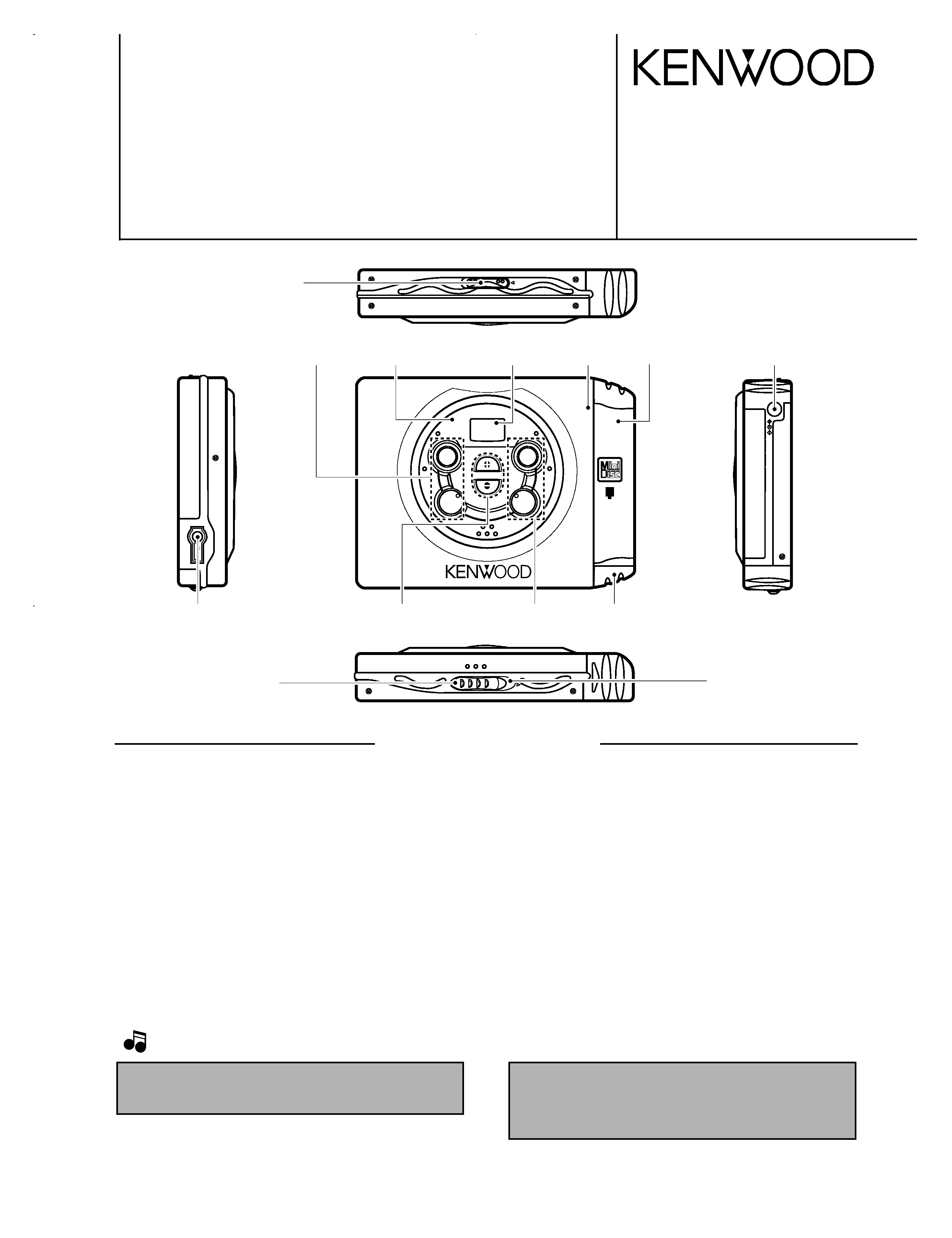
SPECIFICATIONS
POTABLE MD PLAYER
DMC-J3
SERVICE MANUAL
© 1998-3/B51-5411-00 (K/K) 3163
DISPLAY
VOL.
UP
V
O
L.
DO
WN
S
T
O
P
/ O
FF
PL
A
Y
/ P
A
U
S
E
POR
TABLE
MD PLAYER DM
C-J
3
TRACK NO.
BATTERY
7
£
¢
Ni-MH/ALKALINE
COMPATIBLE
4
DC
IN
HOLD
OPEN
PHONES
Knob*
(K29-)
Dressing panel*
(A21-)
Front glass
(B10-2407-04)
Lid assy*
(A53-)
Battery cover*
(A09-)
Dressing panel*
(A21-)
DC jack
(E03-0357-05)
Knob*
(K29-)
Knob
(K29-6828-03)
Blind plate
(F19-1086-04)
Knob*
(K29-)
Knob
(K29-6827-03)
Miniature phone jack
(E11-0381-05)
In compliance with Federal Regulations, following are reproduc-
tions of labels on, or inside the product relating to laser product
safety.
KENWOOD-Corp. certifies this equipment conforms to DHHS
Regulations No. 21 CFR 1040. 10, Chapter 1, Subchapter J.
DANGER : Laser radiation when open and interlock defeated.
AVOID DIRECT EXPOSURE TO BEAM.
1. KENWOOD follows a policy of continuous advancements in development, For reason specifications may be changed without notice.
2. The full performance may not be exhibited in an extremely cold location (under a water-freezing temperature).
Notes
Notes
* Refer to parts list on page 17.
System ............................ Mini disc digital audio system
Read method .................. Noncontact optical reading system
(semiconductor laser)
Sampling frequency ...... 44.1 kHz
Audio compression ....... ATRAC (Adaptive Transform Acoustic Cording)
Number of channels...... 2 channels
Frequency response ...... 20 Hz to 20,000 Hz (
± 3 dB)
Wow & flutter ................ Less than unmeasurable limit
(
± 0.001 % W.PEAK)
Input/Output terminal .. Remote control/Phones jack
Rated power output ......
......
......
......
......
........
9 mW+9 mW
Power source
DC IN jack (4 5.1V)
: Specially provided AC adaptor
: Car battery adaptor (sold separately, DC-C70)
DC 1.5V : Commercially sold AA alkaline battery (LR-6)X 1
DC 1.2V : Specially provided rechargeable battery (NB-130) X 1
(Charging time : About 4 hours)
Battery life (Fully charge, with "auto PS" setting ON)
Specially provided rechargeable battery (NB-130) X 1
..........................
..........................
..........................
Approx. 5 hours
Commercially sold AA alkaline battery (LR-6)X 1
......................
......................
......................
Approx. 6 hours
· At 0.5mW+0.5mW output (32 load ).
· Standard value during continuous use/charging in an temperature of
25°C.
· Time of use may vary depending on battery maker, battery
type, use environment,and temperatute.
· Time will be shorter when "PSoff" Mode is set.
Dimensions (not including protruding parts)
W :99 mm (3-7/8")
H :17 mm (11/16")
D :75 mm (2-15/16")
Weight (Net) ................ 115g (0.25 lb)
not including the accessory rechargeable batter
140g (0.31 lb)
including the accessory rechargeable battery
DMC-J3(K)1P(98.4.2519:57 y[W 2
DMC-J3
2
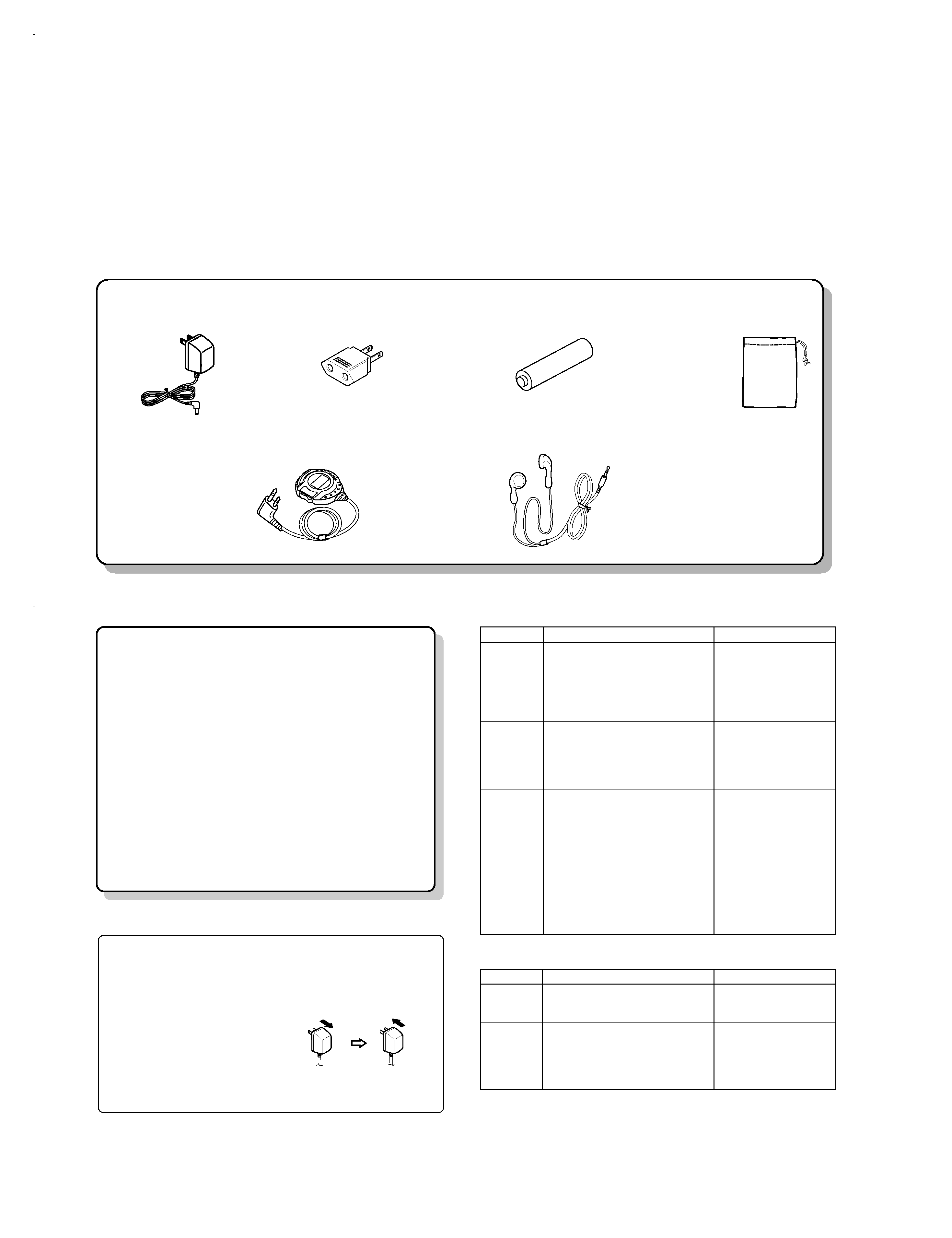
CONTENTS / ACCESSORIES
AC adapter (1) *
(W09-)
Remocon (1)
(A70-1186-05)
Stereo headphone (1) *
(W01-)
* Refer to parts list on page 17.
Batteries : NB130 (1)
(W09-1237-05)
AC plug adapter (1)
(E03-0115-05)
Carrying case (1)
(W01-0938-05)
Contents
Accessories
Caution
SPECIFICATIONS .........................................Top cover
CONTENTS / ACCESSORIES ....................................2
CONTROLS .................................................................3
CIRCUIT DESCRIPTION .............................................4
PC BOARD ................................................................11
SCHEMATIC DIAGRAM ............................................12
EXPLODED VIEW .....................................................15
PARTS LIST...............................................................17
Action
÷ Insert a MD into the unit.
÷ Replace the disc with aprerecorded
MD when playing it back.
÷ Replace the MD.
÷ Replace the MD.
÷ Wait until the inside of the unit
cools down.
Symptom
Cause
Remedy
÷ The disc holder is not securely closed.
÷ The battery is depleted.
÷ HOLD status is engaged.
÷ The volume is at minimum level.
÷ The remote control or headphones are
disconnected.
÷ HOLD status is engaged.
÷ The battery is depleted.
÷ The remote control or headphone plug is
not securely inserted.
÷ The
The MD disc has, a scratch or apoor recording
disc holder is not securely closed.
÷
÷ The unit is in a place where there is
excessive vibration.
÷ You are using commercial rechargeable battery.
÷ The unit has become hot because of
exposure to direct sunlight etc.
÷ You are using another AC adaptor than
the accessory adaptor.
÷ The AC adaptors has become disconnected.
Unit fails to
turn ON.
÷ Close disc holder securely.
÷ Charge the battery.
÷ Deactivate HOLD status.
÷Increase the volume.
÷Insert plug securely.
÷ Deactivate HOLD status.
÷ Charge the battery.
÷ Insert plug securely.
÷ Close disc holder securely.
÷ Replace the MD.
÷ Move the unit to a place
where there is little vibration.
or set to "PS off" .
÷ Use the special rechargeable
battery (NB-130)
÷ Wait until the unit has cooled
to normal temperature.
÷ Use the accessory AC adaptor.
÷ Connect the AC adaptor securely.
There is no
sound.
The unit does
not respond to
key operation.
Sound skips.
Troubleshooting
Message
Meaning
÷ There is no MD in the unit.
÷ Nothing is recorded on this MD.
÷ The * UTOC contents are faulty.
÷ The disc is scratched or damaged, so
Playbackis not possible.
÷ The inside of the unit has become hot
during charging.
"BLANK
"
"noDISC"
" LoBATT "
"ERROR "
Meaning of display messages
* UTOC : UTOC (User's Table of Contents) refers to special data put on a recordable MD,
other than TOC data.. UTOC contains writable data such as number of songs,
performance time, and other written data.
Battery does
not charge.
Resetting the unit
The unit may not operate normally due to faulty handling or adverse power current
effects caused by impact, excessive static electricity load, or power drop during use.
If this occurs, take the following measures.
1Pull the AC adaptor out of the
power outlet.
2Remove the rechargeable
battery.
3Wait about 30 seconds.
4Plug the AC adaptor into the
power outletand operate the
unit.
To household outlet
Beware of condensation
When water vapor comes into contact with the surface of cold materi-
al, water drops are produced.
If condensation occurs, correct operation may not be possible, or the
unit may not function correctly.
This is not a malfunction, however, and the unit should be dried.
(To do this, turn the POWER switch ON and leave the unit as it is for
several hours.)
Be especially careful in the following conditions:
· When the unit is brought from a cold place to warm place, and there is
a large temperature difference.
· When a heater starts operating.
· When the unit is brought from an air-conditioned place to a place of
high temperature with high humidity.
· When there is a large difference between the internal temperature of
the unit and the ambient temperature, or in conditions where conden-
sation occurs easily.
DMC-J3(K)1P(98.4.2519:57 y[W 3
DMC-J3
3
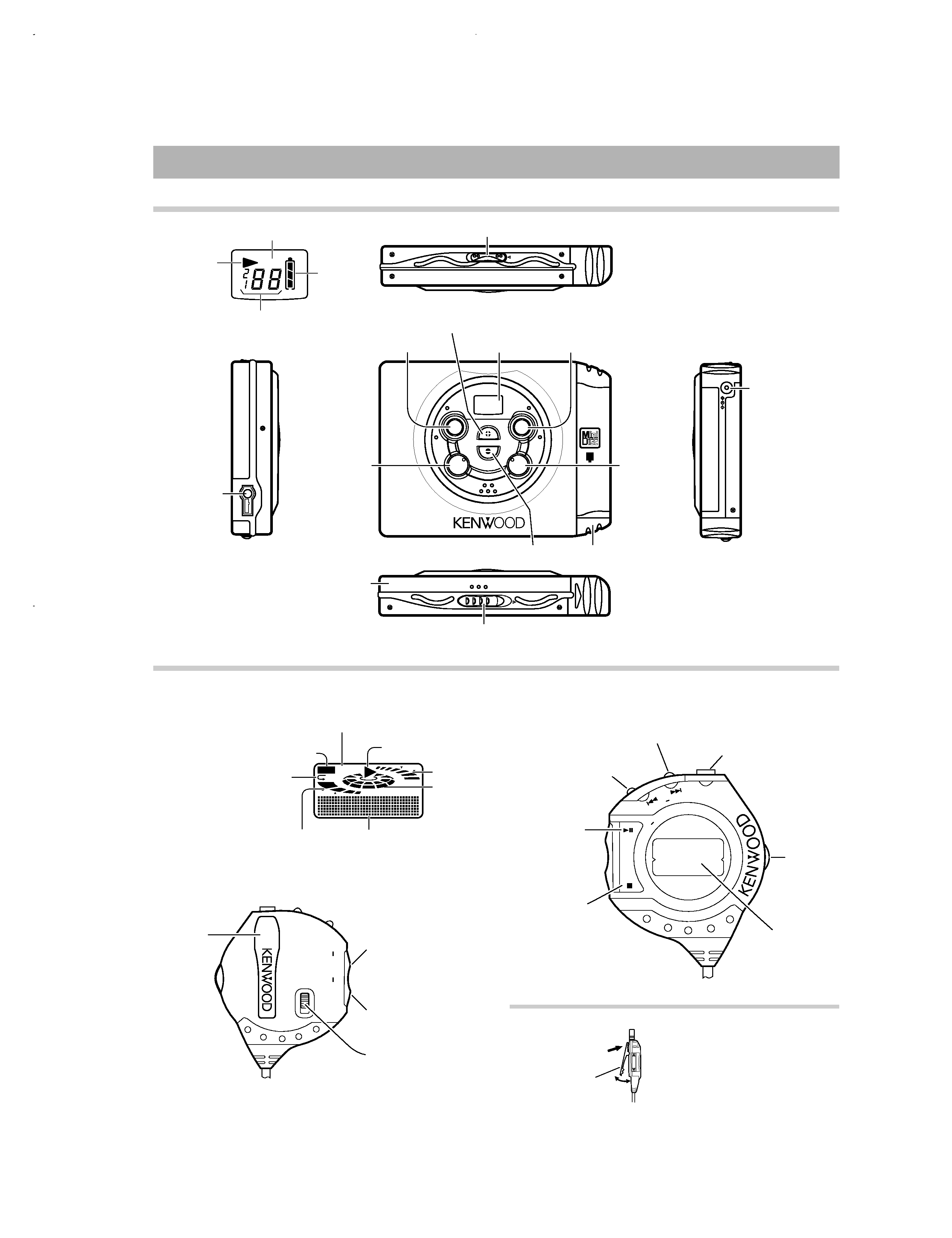
CONTROLS
SHIFT B.B.
ALL
F
MAX
DISPLAY
VOL.
UP
V
O
L.
DO
WN
S
T
O
P
/ O
FF
PL
A
Y
/ P
A
U
S
E
POR
TABLE
MD PLAYER DM
C-J
3
TRACK NO.
BATTERY
7
£
¢
Ni-MH/ALKALINE
COMPATIBLE
4
DC
IN
HOLD
OPEN
PHONES
HOLD
S
T
O
P
/O
F
F
P
L
A
Y
/P
A
U
S
E
PL
AY
MO
DE
SK
IP
SEAR
CH PHONE
S
PLAY OPERATION
VOLUME
TITLE/TRACK NO./TIME
BATTERY
SHIFT
E
LE
CTR
O LUMINESC
EN
CE
MD
UP
DISPLAY
DOWN
BASS
BOOST
HOLD
3
Names and functions of parts
HOLD indicator
VOLUME
Using the Clip
÷ The remote control unit can be clipped
to a bag or a pocket.
¢ (SKIP-SEARCH) key
*Fast-forward mode
B.B (Bass boost) indicator
Main Unit
Remote Control
Functions marked with an asterrisk (*) indicate operations performed in SHIFT
Mode.
Play indicator
Track mode indicator
Remaining
battery life
indicator
OPEN knob
PHONES jack
Disc Holder
SHIFT indicator
Play indicator
Volume indicator
Playback
status indicator
Repeat mode indicator
P: One Track Repeat mode
PALL : All Tracks Repeatmode
ALL
: Random mode
Remaining battery
life indicator
Character infromation
indicator
Clip
Volume UP key
*DISPLAY mode
Volume DOWN key
*BASS BOOST mode
HOLD switch
Clip
Press and release.
4 (SKIP-SEARCH) key
*Fast-reverse mode
PHONES jack
SHIFT key
LCD
38 (PLAY/PAUSE
-PLAY MODE) key
* Repeat play mode
* Random play mode
7 (STOP/OFF) key
Battery cover
( (VOL. DOWN ) key
7 (STOP/ OFF) key
9 (VOL. UP) key
LCD
3 (PLAY / PAUSE) key
¢ (Skip up)
key
DC IN jack
(Extemal power
jack)
4 (Skip
down) key
HOLD knob
DMC-J3(K)1P(98.4.2519:57 y[W 6
DMC-J3
4
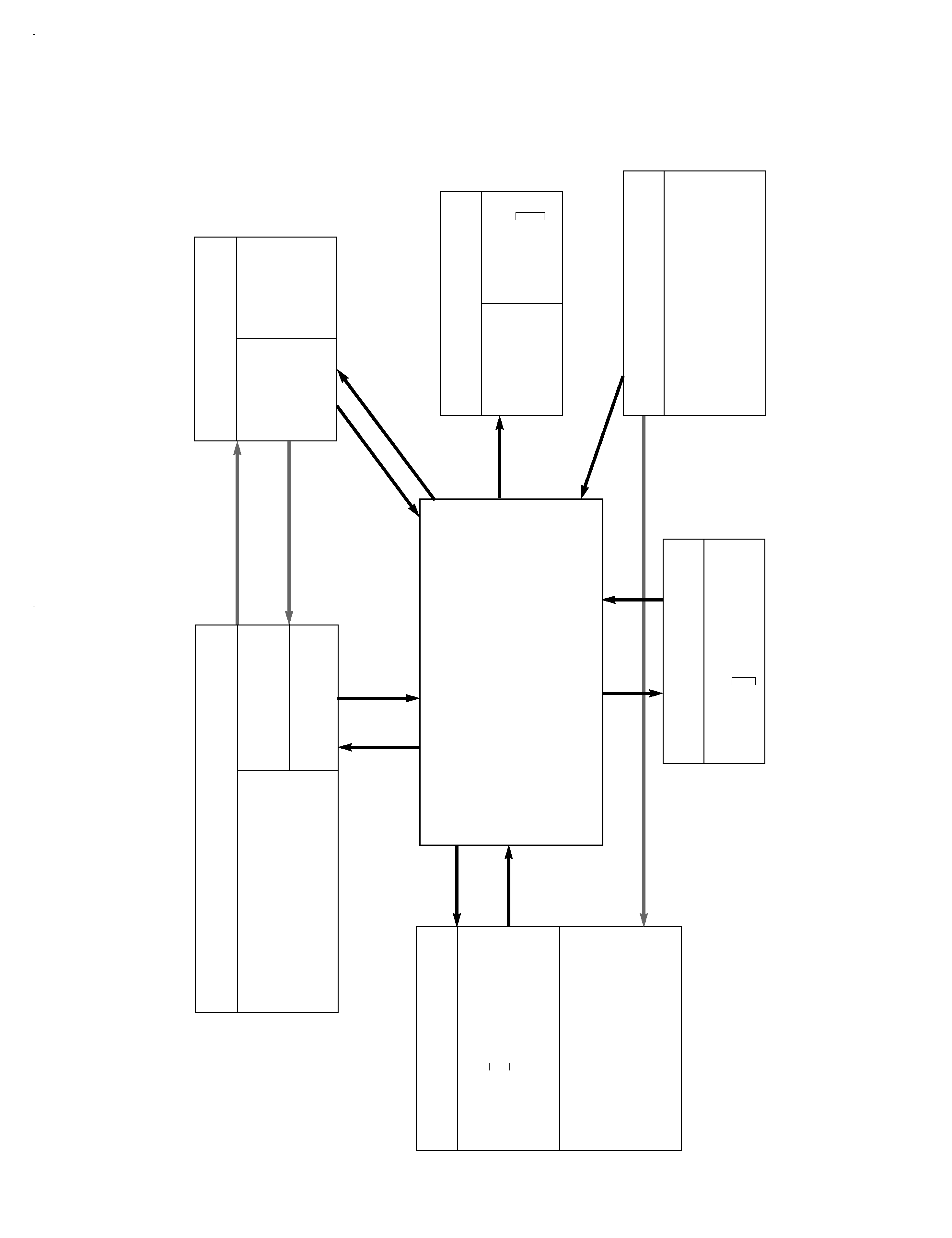
CIRCUIT
DESCRIPTION
1.
Main
microprocessor
:
uPD784035GC810
(X33
:
IC5)
1-1
Microprocessor
periphery
block
diagram
P_AD_BATT1
P_AD_BATT2
A / D input
P_AD_ADP
P_ADON
P_CHG
P_CHGOK
Control
SYSTEM
CXD2655R, CXA2523AR
P_XRST
P_XLAT, P_SWDT, P_SRDT, P_SCLK
P_XINT, P_ADSY
P_SENS
P_FOK
P_SYS_POWER, P_SP
P_XSTBY
Headphone AMP
P_HP_POWER
Motor drive
P_CTL, P_PASS
P_SPOUT (D / A output )
P_SPIN (A / D input )
Mechanism
Pickup
P_LDON
(T25-0071-05)
Mechanism
(D40-1576-01)
Remocon
P_RLCD_DT
Unit
P_MLCD_CK
P_MLCD_DT
P_MLCD_CD
P_MLCD_CS
Display
Operation
Data
Power supply
Other
P_TEST0
P_TEST1
P_NO_JTYPE
P_HOLD
P_WUP
P_BEEP
AK93C45A
P_EP_CLK
P_EP_CS
P_EP_DO
Serial control
P_EP_D
P_AD_KEY0
Unit key
P_AD_KEY1
Remocon key
uPD784035GC810
u-COM IC5
DMC-J3(K)1P(
98.4.25
19:57
y[W
7

Pin No.
Pin Name
I/O
Description
1
/XLAT
O
Control latch to CXD2655R
2
/XRST
O
Reset to CXD2655R
3
NC
O
No use
4
/LDON
O
The laser of the pickup output on/off. L:output.
5
BEEP
O
Beep sound output.
6
NC
O
No use
7
/RESET
Microprocessor reset.
8
VDD
Power supply (+5V).
9,10
X1,2
I
Main clock generation(12MHz).
11
VSS
GND
12
/XSTBY
O
Standby signal output.
13
CTL
O
The feed motor drive signal output.
14
PASS
O
Power save by-pass signal for DC/DC
15
/SP
O
Inverted switch port of the power supply to system and IC .
16,17
NC
O
No use
18
/CHGOK
I
Rechargeable battery OK signal input port. H:NG
19
CHG
O
Rechargeable current control output. H:charge on.
20
SYS POWER
O
The switch port of the power supply to system and IC .
21
MLCD C/D
O
Display driver command check signal output.
22
MLCD C/S
O
Display driver chip select signal output.
23
RLCDDATA
O
Remote control display driver serial control data.
24
PWS
O
Headphone amp output selector. H:output.
25-41
O
No use
42,43
TEST1,0
I
Test mode.
44
NC
O
No use
45
VSS
GND
46
TEST
I
Device test.
47
NC
O
No use
48
EPCLK
O
E2ROM serial control clock output.
49
MLCD CLK
O
Display driver clock signal output.
50
O
No use
51
MCLD DATA
O
Display driver data signal output.
52
EPCS
O
E2ROM serial control latch output.
53
EPDI
O
E2ROM serial control data output.
54
EPDO
I
E2ROM serial control data input.
55
VDD
Power supply (+5V).
56,57
KEY0,1
I
A/D voltage matrix key input. key0=unit,key1=:remocon).
58
ADP
I
A/D external power supply voltage check input.
59
BATT1
I
A/D minus power supply data input.
60
BATT2
I
A/D pulse internal power supply data input.
61
SPIN
I
A/D spindle drive voltage input.
62
/HPLD
I
HPLD switch check output. H:HOLD off.
63
ADON
O
AVREF output.
64
AVDD
Power supply (+5V) for A/D.
65
AVREF1
Reference voltage for A/D.
66
AVSS
GND for A/D.
67
NC
O
No use
5
DMC-J3
CIRCUIT DESCRIPTION
1-2 Pin description
DMC-J3(K)1P(98.4.2519:57 y[W 10