S: SILVER, B: BLUE
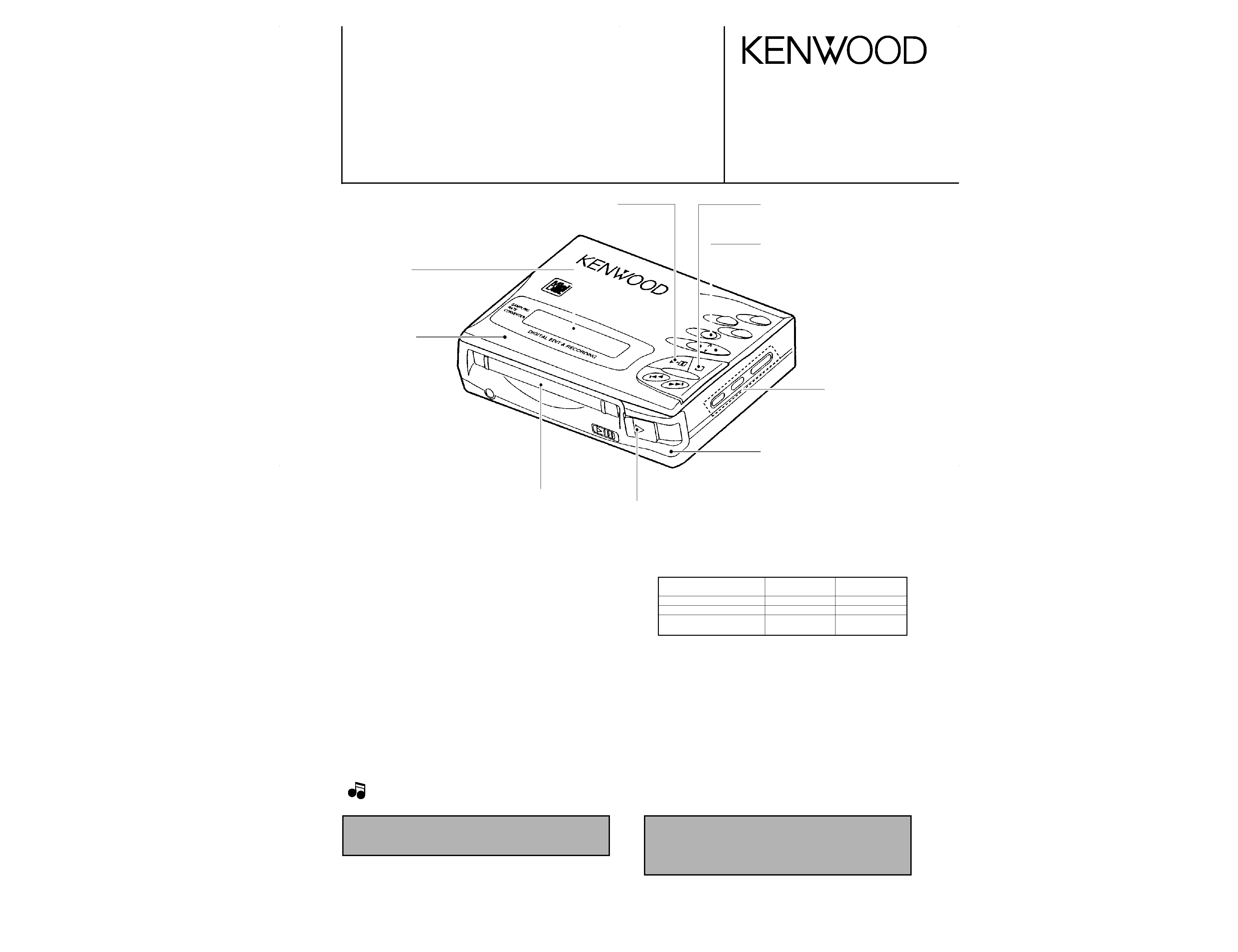
Decoration plate
(B07-2372-08)
Knob (PLAY/PAUSE)
(K27-2229-08)
Knob (STOP)
(K27-2231-08)
Knob (REC)
(K27-2227-08)
Front cabinet
(A02-1357-08): S
(A02-1358-08): B
Knob (EJECT)
(K27-2232-08)
Cover
(F07-1624-08)
Knob (EDIT MODE)
(K27-2230-08)
Top cover
(F07-0798-08): S
(F07-0799-08): B
POTABLE MD RECORDER
DMC-G7R
SERVICE MANUAL
© 1997-7/B51-5335-00 (K/K) 2740
In compliance with Federal Regulations, following are reproduc-
tions of labels on, or inside the product relating to laser product
safety.
KENWOOD-Corp. certifies this equipment conforms to DHHS
Regulations No. 21 CFR 1040. 10, Chapter 1, Subchapter J.
DANGER : Laser radiation when open and interlock defeated.
AVOID DIRECT EXPOSURE TO BEAM.
SPECIFICATIONS
System .........................................................MiniDisc digital audio system
Read method ...Noncontact optical reading system (semiconductor laser)
Rotating speed ..........................................................About 400 - 900 rpm
Sampling frequency..............44.1 kHz (32 kHz and 48 kHz are converted
to 44.1 kHz and recorded)
Audio compression...........ATRAC (Adaptive Transform Acoustic Coding)
Number of channels ...................................................Stereo : 2 Channels
Monaural Extended mode : 1 channel
Recording method.........................Magnetic modulation overwrite system
Error correction method ...................................................AC / RC method
Frequency response.......................................20 Hz to 20,000 Hz (±3 dB)
Wow & flutter .............Less than unmeasurable limit (±0.001 % W.PEAK)
Input jack........................Line/optical combined input x 1; microphone x 1
(plug-in power type)
Output jack ..............................Headphone/remote control combined jack
Input sensitivity : MIC H .....................................................0.25 mV/10 k
MIC L........................................................2.5 mV/10 k
LINE ........................................................100 mV/20 k
Output level : phones.....10 mW + 10 mW (Maximum output level/at 16
)
LINE ..................350 mV (at -12dB, standard output/50 k
)
Power source...DC 5 V
: AC adaptor (AC 120 V, 50/60 HZ)
DC 3.6 V : Lithium ion battery x 1
DC 5 V
: Car battery adaptor (sold separately, DC-C50)
DC 4.5 V : Dry batteries case (sold separately, BC-F5)
Battery life ..................................................................................................
(fully charged batteries)
Dimensions (W) x (H) x (D) ....................109.2 mm x 29.8 mm x 81.3 mm
(4-5/16" x 1-3/16" x 3-3/16")
Weight (Net) .................Approx. 270 g (0.59 lb)
Including the accessory rechargeable battery
Approx. 222g (0.49 lb)
not including the accessory rechargeable battery
(Continuous recording time : based on analog input and recording
monitor volume level of "0"
(Continuous playback time : based on volume level of "VOL 20")
· Time of use may vary depending on battery maker, batter type,
use environment, and temperature.
1. KENWOOD follows a policy of continuous advancements in development, For reason specifications may be changed without notice.
2. The full performance may not be exhibited in an extremely cold location (under a water-freezing temperature).
Type of battery
Continuous
Continuous
playback time
recording time
Rechargeable battery only Approx. 9.5 hours Approx. 7 hours
Alkaline batteries
Approx. 24 hours Approx. 17 hours
Rechargeable battery +
Approx. 35 hours Approx. 25 hours
Alkaline batteries
Notes
Notes
DMC-G7R(k) COVER( 98.4.24 2:19 PM y[W 2
DMC-G7R
2
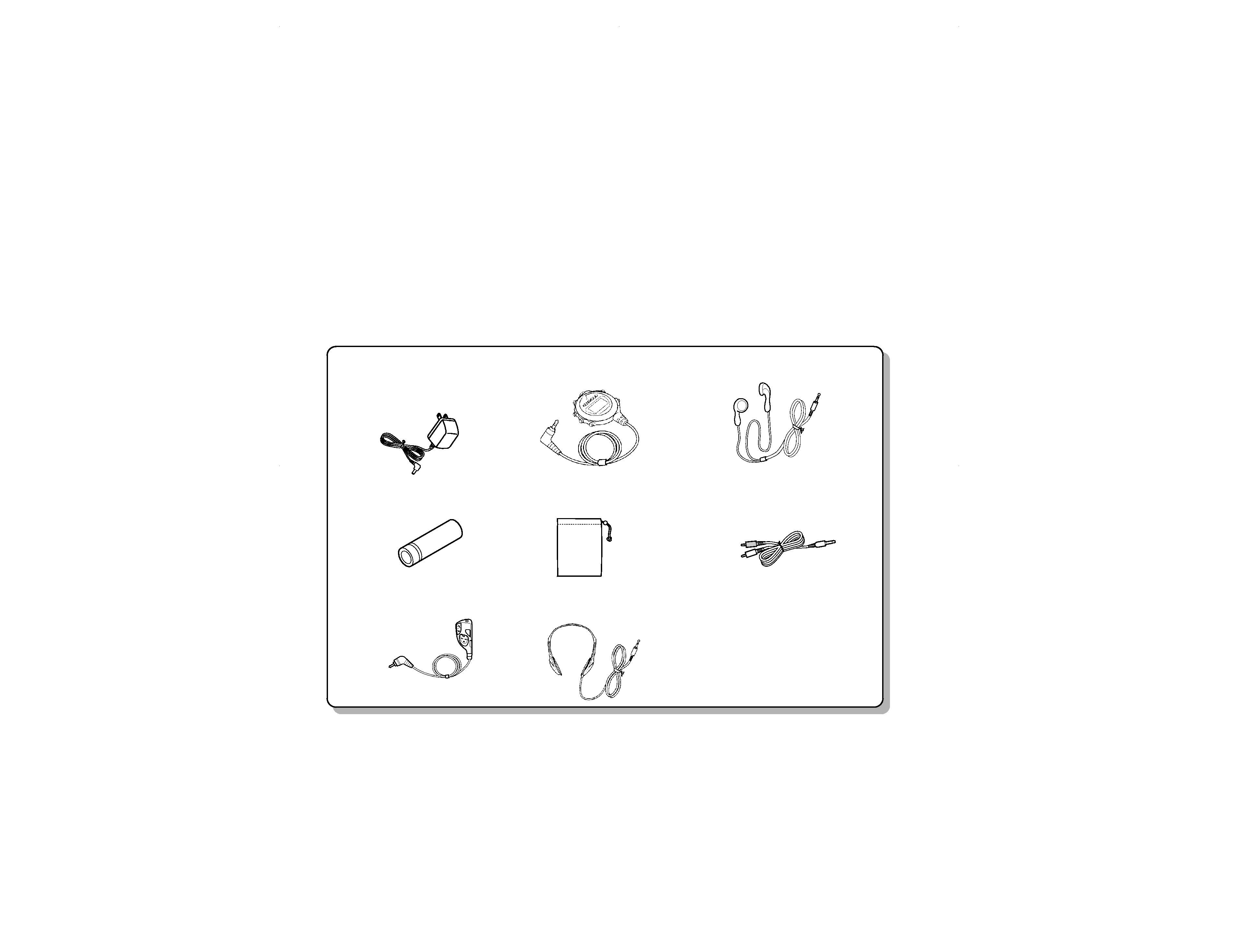
CONTENTS / ACCESSORIES
Accessories
AC adaptor(1)
(W08-0668-08) : K
(W08-0669-08) : M
(W08-0670-08) : E
(W08-0671-08) : T
Rechargeable battery (NB-L5) (1)
(W03-5679-08)
Remote control (1)
(A70-1129-05) : M
Remote control unit (1)
(A70-1177-05) : KET
Carrying case (1)
(W01-0918-08)
Stereo headphone(1)
(W01-0920-15) : MET
Stereo headphone(1)
(W01-0941-15) : K
Patch cord (1)
(E30-2836-08)
Contents
SPECIFICATIONS .......................................Front cover
CONTENTS / ACCESSORIES ....................................2
DISASSEMBLY FOR REPAIR .....................................3
TROUBLE SHOOTING ................................................5
PC BOARD ................................................................19
SCHEMATIC DIAGRAM ............................................23
EXPLODED VIEW .....................................................27
PARTS LIST...............................................................29
DMC-G7R(k) COVER( 98.4.24 2:19 PM y[W 3
Caution on Disassembly
Follow the below-mentioned notes when disassembling
the unit and reassembling it, to keep it safe and ensure
excellent performance:
1. Take the battery and minidisc out of the unit.
2. When disassembling the machine, be sure to withdraw
the power plug from the socket in advance.
3. When disassemble the parts, remove the nylon band or
wire holder as necessary.
To assemble after repair, be sure to arrange the wires as
they were.
If a screw of different length is fitted to the MD mecha-
nism (the screw of the part to be fitted to the MD
mechanism chassis), it may contact the optical pickup,
resulting in malfunction.
4. When repairing, pay due attention to electrostatic charges
of IC.
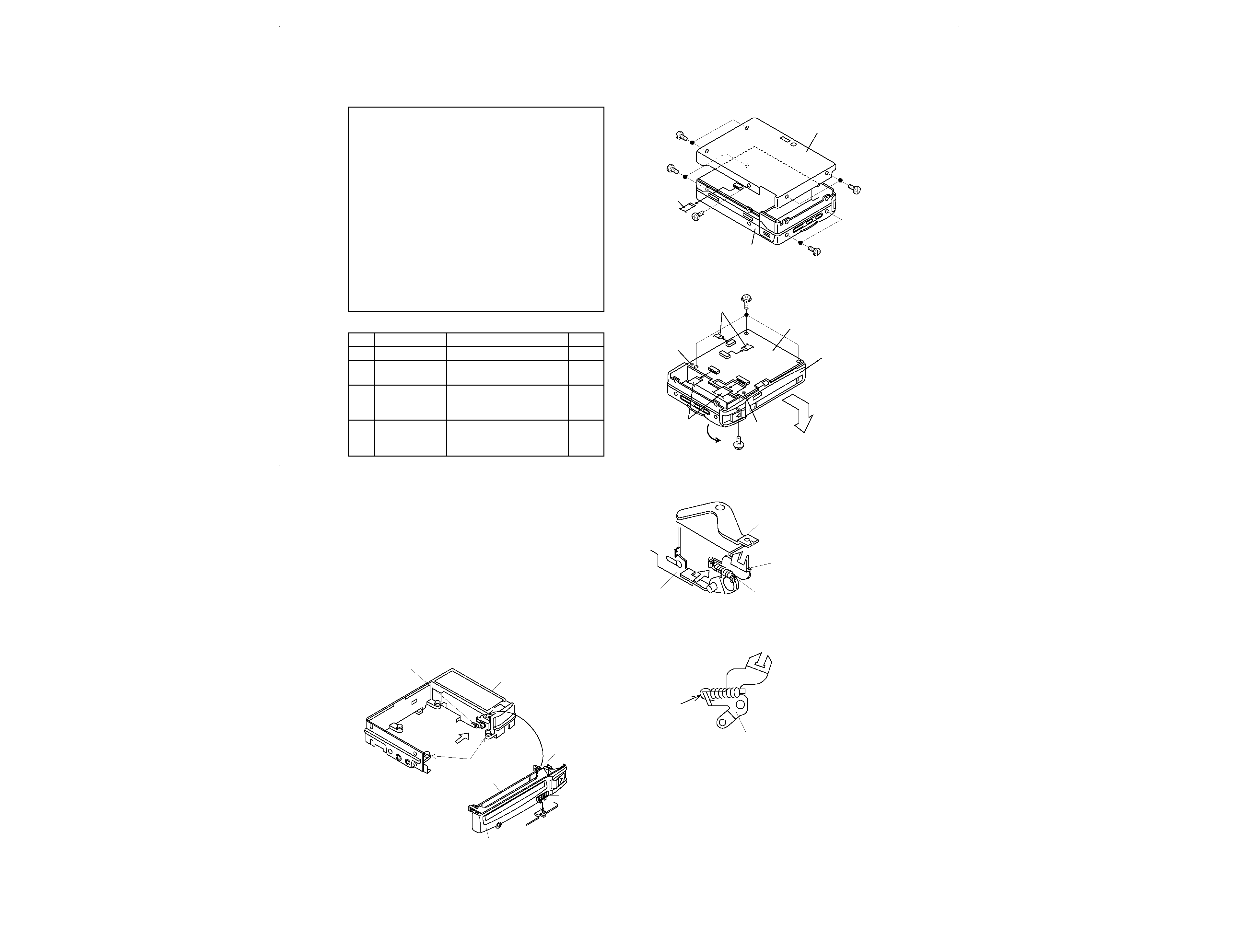
1
Bottom Cover
1. Screw ..................... (A1) x5
7-1
2
Disc Cover
1. Screw ..................... (B1) x4
7-1
(Note)
2. Flexible PWB ......... (B2) x1
3
Main PWB
1. Screw ..................... (C1) x3
7-2
2. Flexible PWB ......... (C2) x4
3. Soldering ............... (C3) x2
4
Front Cabinet
1. Screw ..................... (D1) x1
7-2
2. Remove the front cabinet in
the arrow direction.
REMOVAL
PROCEDURE
STEP
FIGURE
Bottom Cover
(B1) x2
Ø2x2mm
(B1) x2
Ø2x2mm
(A1) x2
Ø2x2mm
(A1) x2
Ø2x2mm
(A1) x1
Ø2x2mm
(B2) x1
Disc Cover
Figu re 7-1
Figure 7-2
Eject knob lever
Eject lever
Lid opening and closing spring
Lid opening and closing spring
Lid opening and closing lever
Engage the spring
at the upper side.
Lid opening and closing lever
<A>
Figure <A>
Figure 7-3
Figure 7-4
Note:
When removing the upper lid, at first turn the operation knob
side in the arrow direction to remove.
Installing the front cabinet (See Fig. 7-3.)
1. Make sure that the lid opening and closing spring has been
engaged at the upper side as shown in Figure < A > .
2. Fit the MD lid right pin into the lid opening and closing lever
to install it.
Note:
· Take care since the antivibration rubber may come off.
· If the main PWB has been installed previously, fit the knob to
the HOLD switch shown in Figure < B > .
· If the mechanism has been installed, the antivibration rubber
may come off from the center cabinet fitting part when the
front part of center cabinet is widened.
(C1) x3
Ø2x2.5mm
(D1) x1
Ø2x2.5mm
(C3) x1
(C2) x2
(C3) x1
Main PWB
Front Cabinet
(C2) x2
Front Cabinet
Lid opening and closing lever
Center Cabinet
<A>
Antivibration rubber
HOLD knob
MD lid
MD lid right pin
SW
<B>
DMC-G7R
3
DISASSEMBLY FOR REPAIR
DMC-G7R(k) COVER( 98.4.24 2:19 PM y[W 6
DMC-G7R
4
DISASSEMBLY FOR REPAIR
Remove the mechanism according to the disassembling meth-
ods 1 to 4. (See Page 7.)
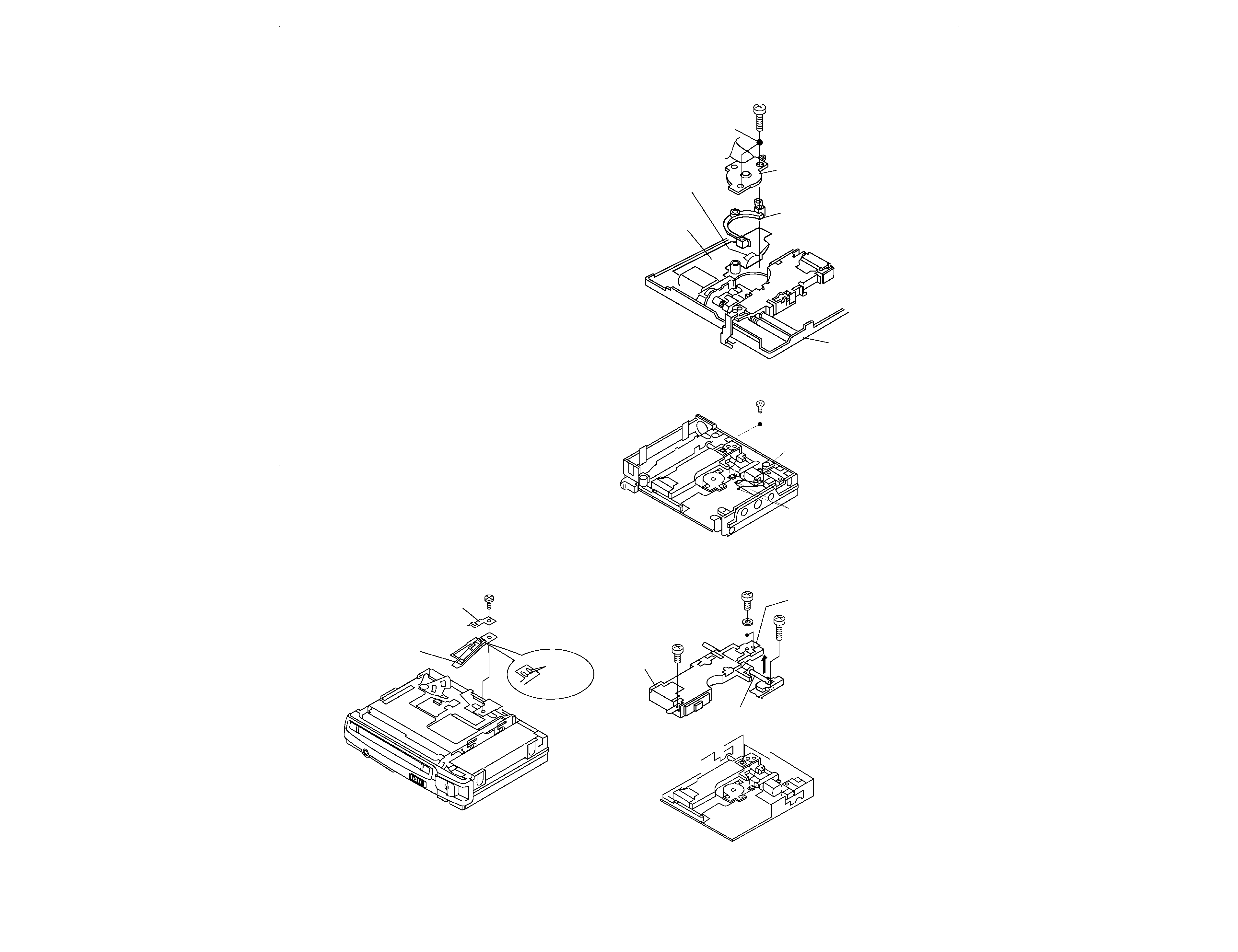
How to remove the disc motor (See Fig. 8-1.)
1. Remove the solder joint (A1) x 1 of flex PWB.
2. Remove the screws (A2) x 3 pcs. and remove the disc
motor.
Take care so that the turnrable is not damaged.
Figure 8-4
(A2) x 3
Ø1.4 x 4.5mm
Flexible PWB
solder joint
(A1) x1
Disc Motor
Motor Spacer
Mechanism PWB
Mechanism
Figure 8-1
(B2) x2
Ø1.4x2.2mm
(B1) x2
Remove the solder joint.
Slide Motor
Figure 8-2
Figure 8-3
Shaft (C2) x 1
(C1) x 2
Ø1.4 x 3mm
(C1) x 1
Ø1.4 x 2.5mm
(C1) x 1
Ø2 x4.5mm
Pickup Unit
Magnetic field arm block
Magnetic head
Head intervening flexible PWB
(D1) x1
Ø1.4x2mm
Unsolder
(D2) x2
How to remove the slide motor (See Fig. 8-2.)
1. Remove the solder joint (B1) x 1 of slide motor lead wire.
2. Remove the screw (B2) x 1, and remove the slide motor.
Note:
Take care so that the motor gear is not damaged.
(If the gear is damaged, noise is raised in search mode.)
How to reinstall the optical pickup unit
(See Fig. 8-3.)
1. Remove the screws (C1) x 5 pcs.
2. Remove the magnetic fielt arm block from the pickup, and
move the magnetic field arm block outwards.
Note:
Take due care so that the magnetic head is not damaged.
3. Withdraw a little the slide motor side shaft (C2) x 1 pcs., and
slowly raise the optical pickup.
How to remove the magnetic head
(See Fig. 8-4.)
1. Remove the screw (D1) x 1 pc.
2. Remove the unsolder (D2) x 2 pcs. which connects the
magnetic head and the head hookup flex.
Note:
Mount carefully so as not to damage the magnetic head.
DMC-G7R(k) COVER( 98.4.24 2:19 PM y[W 7
DMC-G7R
5
TR
OUBLE
SHOO
TING
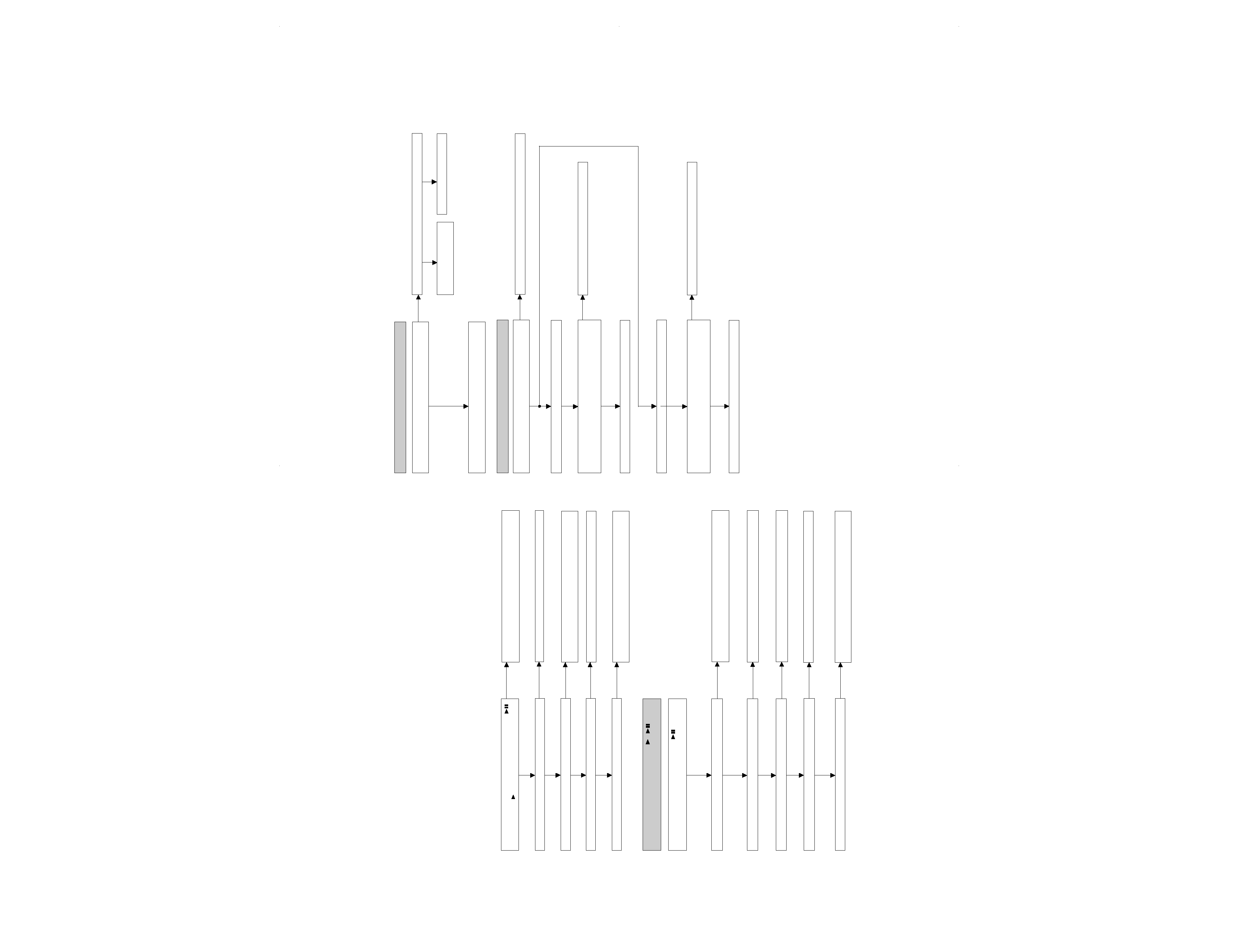
· Abnormal display
No
Yes
Is waveform output from IC 401 pins 13 to 15?
Check for pattern breakage of flexible PWB, check for
defects of display microcomputer (replace the display unit).
Is waveform output from CNS 402 pins 1 to 3?
Are the pin7 (VCC) and pin 6 (GND) normal?
· Playback state cannot be set
Is playback state unsettable for high reflection disc and low
reflection disc?
Yes
Check between IC401 and
CNS402.
No
Check the periphery of IC401.
Proceed to "Test mode check".
Yes
Only the low reflection disc cannot be played back.
Only the high reflection disc cannot be played back.
Yes
Is the pin 46 of IC401 in L state when the high reflection disc
is inserted?
Is the pin 51 of IC401 and pin 23 of IC101 in L state?
Check SW902, mechanism flexible PWB and CN601.
No
Proceed to "Test mode check".
Yes
No
Yes
Is the pin 46 of IC401 in L state when the high reflection disc
is inserted?
Is the pin 51 of IC401 and pin 23 of IC101 in L state?
No
Proceed to "Test mode check".
Yes
Check SW902, mechanism flexible PWB and CN601.
It is advisable to use the TEST mode (refer to Error Data Display Mode, P15) indicating the causes of troubles before
starting repair. Causes of operation errors (up to 10 errors) are recorded as error codes. This information is useful
for repair.
When does not function
When the CD section does not operate When the objective lens of the optical pickup is dirty,this section may not operate.Clean
the objective lens,and check the playback operation.When this section does not operate even after the above step is taken,check
the following items.
Remove the cabinet and follow the troubleshooting instructions.
"Track skipping and/or no TOC(Table Of Contents) may be caused by build up of dust other foreign matter on the laser pickup lens.
Before attempting any adjustment make certain that the lens is clean. If not, clean it as mentioned below."
Turn the power off.
Gently clean the lens with a lens cleaning tissue and a small amount of isopropyl alcohol.
Do not touch the lens with the bare hand.
Is the power supply turned on when the remote control
button or main unit
button is pressed?
No
Perform the check stated in item "Power is not turned on
when the PLAY button is pressed".
Perform the check stated in item "Abnormal display".
No
Yes
Does the display operate normally?
Is playback state set?
Yes
Perform the check stated in item "Playback state connot be
set".
No
Is audio output normal?
Yes
Perform the check stated in item "Audio playback circuit".
No
Is recording/playback operation normal?
Yes
Perform the check stated in item "Recording/playback
operation".
No
· Power is not turned on when the
/
button
is pressed.
No
No
Yes
Check the periphery of remote controller and main unit
headphone terminal (J703) and IC401.
No
Is the pin 26 of IC401 in H state?
Is operation normal when the main body button is pressed?
Check the position of Hold switch.
Is power turned on when the remote control
button is
pressed?
No
Are IC401 pin 50 set to "L"?
Check the DISC IN (SW904) switch of mechanism PWB.
Yes
Yes
Is clock supplied to the pins 83 and 86 of IC401?
No
Check that voltage is applied to the periphery of IC403.
Yes
Is 2.5V applied to TP201?
No
Check whether there is solder touch of part connected to
the +2.5V line.
DMC-G7R(k)
COVER(
98.4.24
2:19
PM
y[W
10