In compliance with Federal Regulations, following are
reproductions of labels on, or inside the product relating to
laser product safety,
KENWOOD-Corp. certifies this equipment conforms to
DHHS Regulation No.21 CFR 1040.10, Chapter 1,
Subchapter J.
DANGER : Laser radiation when open and interlock
defeated.
AVOID DIRECT EXPOSURE TO BEAM.
*Refer to parts list on page 49.
STEREO MINIDISC RECORDER
DM-3090
SERVICE MANUAL
© 1997-11/B51-5396-00 (K/K) 1812
MULTI CONTROL
TIME DISPLAY
DISPLAY/CHARAC.
TRACK/EDIT
ON/STAND BY
STEREO MINIDISC RECORDER
TIMER/
DELETE
ENTER
REC
REC LEVEL
0
10
PHONES LEVEL
MIN
MAX
PHONES
R
L
R
L
PLAY
OUT
REC
IN
DIGITAL
LINE
2 REC IN
1 REC IN
PLAY OUT
OPT.
RESET
KENWOOD badge
(B43-0302-04)
Front glass
(B10-2457-08)
Front panel
(A60-1370-08)
Knob (JOG)
(K29-6946-08)
Knob (REC/HP)
(K29-6947-08)
AC power cord bushing
(J42-0338-08)
AC power cord *
(E30-)
Optical digital output
(W02-2643-08)
Switch (RESET)
(S68-0091-08)
Analogue output terminal
(E63-1031-08)
Optical digital input
(W02-2643-08)
Knob (POWER)
(K27-2261-08)
Knob
(K27-2262-08)
Head phone jack
(E11-0345-08)
Panel
(A29-0898-08)
Digital input terminal
(E63-1032-08)
DM-3090(K) COVER 97.11.29 0:18 AM y[W 2
If a problem occurs
If this product is subjected to strong external interference
(mechanical shock, excessive static electricity, abnormal
supply voltage due to lightning, etc.) or if it is operated
incorrectly, it may malfunction or the display may not
function correctly. If such a problem occurs, do the
following:
·
Unplug the AC power lead from the AC socket.
·
Wait about 20 - 30 seconds and then plug the AC power
lead back into the AC socket.
·
Press the reset key on the back of the unit.
· When the reset key is pressed, all of the settings in memory
will be erased.
R
L
R
L
PLAY
OUT
REC
IN
DIGITAL
LINE
2 REC IN
1 REC IN
PLAY OUT
OPT.
RESET
RESET
Beware of condensation
When water vapor comes into contact with the surface of
cold material, water drops are produced. If condensation
occurs, correct operation may not be possible, or the unit
may not function correctly.
This is not a malfunction, however, and the unit should be
dried.
(To do this, turn the POWER switch ON and leave the unit
as it is for several hours.)
Be especially careful in the following conditions:
· When the unit is brought from a cold place to a warm place
and there is a large temperature difference.
· When a heater starts operating.
· When the unit is brought from an air-conditioned place to
a place of high temperature with high humidity.
· When there is a large difference between the internal
temperature of the unit and the ambient temperature, or in
conditions where condensation occurs easily.
6
1
9
+
1
0
2
3
4
5
7
8
0
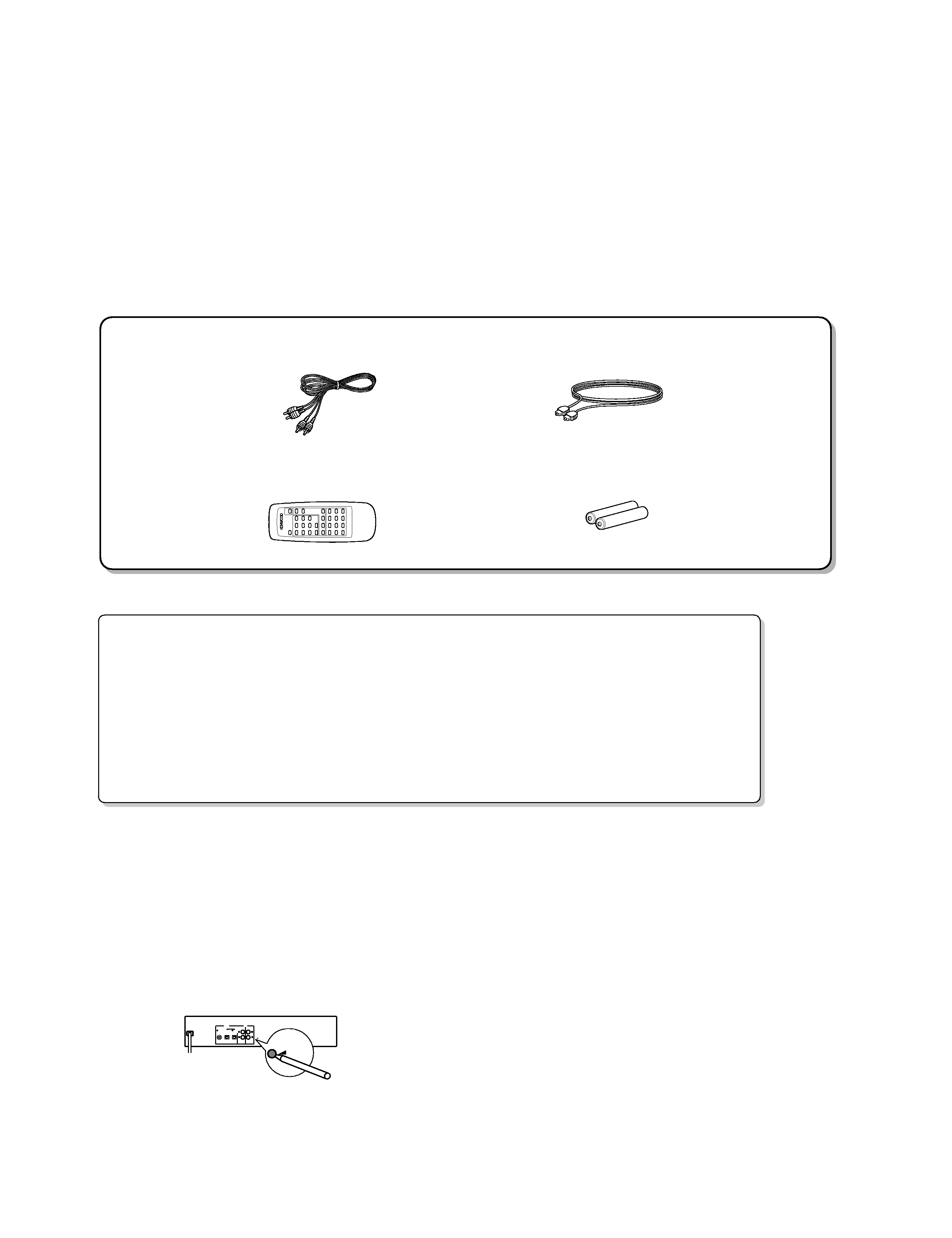
Remote control unit (1)
(A70-1208-08)
Battery cover (A09-0337-08)
Audio cord (2)
(E30-0505-05)
Optical fiber cable (1)
(B19-1529-05)
Batteries (2)
DM-3090
2
CONTENTS/ACCESSORIES/CAUTIONS
CONTENTS/ACCESSORIES/CAUTIONS ...................2
CONTROLS .................................................................3
DISASSEMBLY FOR REPAIR .....................................5
BLOCK DIAGRAM .......................................................7
CIRCUIT DESCRIPTION .............................................9
TROUBLE SHOOTING ..............................................16
ADJUSTMENT ...........................................................24
PC BOARD ............................................................... 32
SCHEMATIC DIAGRAM ........................................... 37
EXPLODED VIEW .....................................................47
PARTS LIST...............................................................49
SPECIFICATIONS .......................................Back cover
CONTENTS
Accessories
Cautions
DM-3090(K) COVER 97.11.29 0:18 AM y[W 3
Names and functions of parts
MULTI CONTROL
TIME DISPLAY
DISPLAY/CHARAC.
TRACK/EDIT
ON/STAND BY
STEREO MINIDISC RECORDER
TIMER/
DELETE
ENTER
REC
REC LEVEL
0
10
PHONES LEVEL
MIN
MAX
PHONES
1
2
3
4 5 6
7 8 9
0 !
@
#
$
%
^
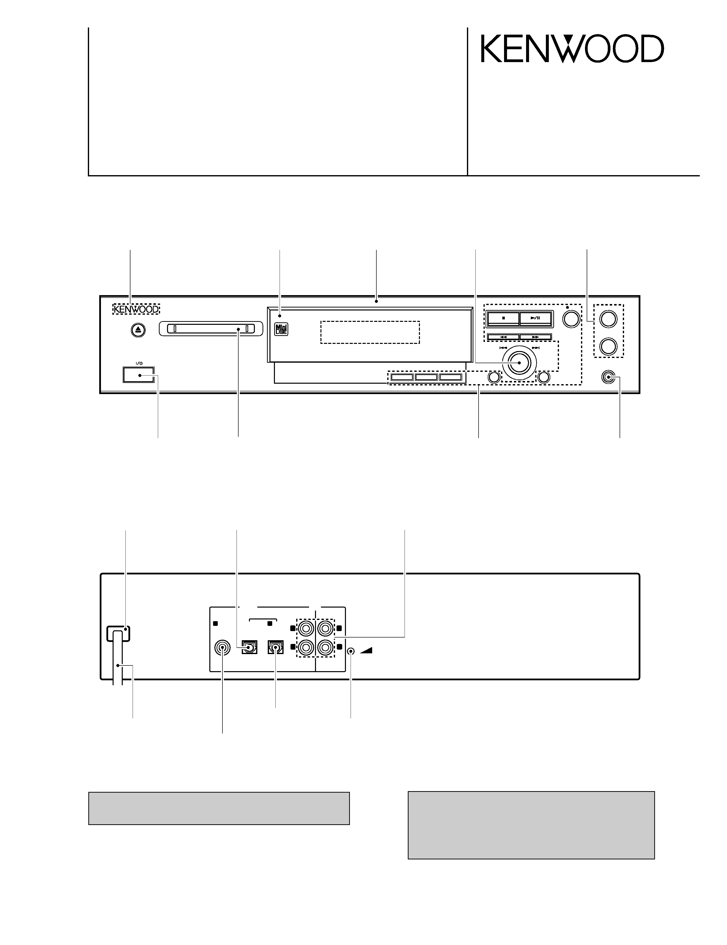
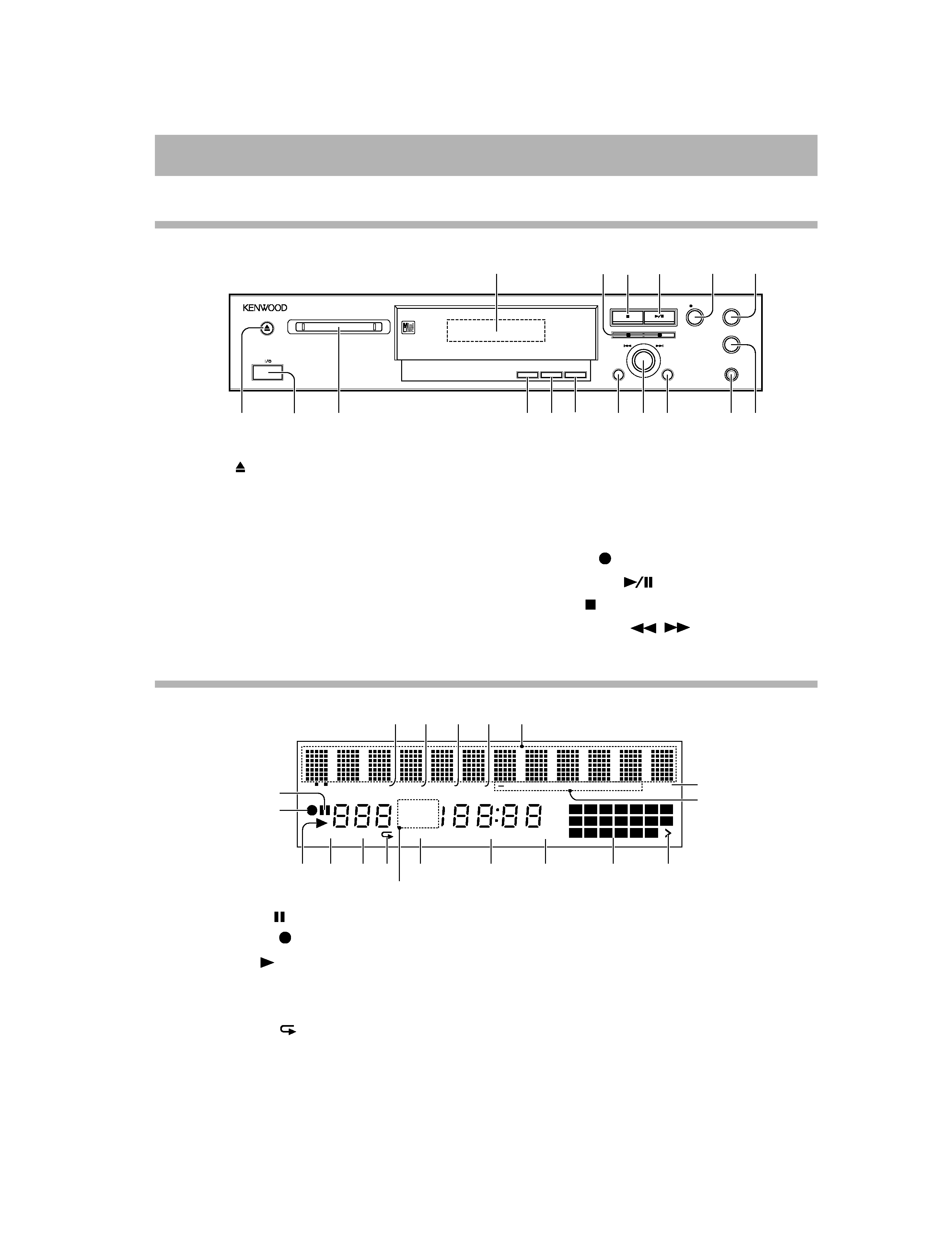
1 Eject key:
2 Power switch (ON/STAND BY key)
3 Mini Disc Insertion slot
4 TIME DISPLAY key
5 DISPLAY/CHARAC key
6 TRACK/EDIT key
7 TIMER/DELETE key
8 Jog dial (Next/Previous)
9 ENTER key
0 Headphone jack (HONES)
! Headphone output level control
@ Record level control
# Record key:
$ Play/Pause key:
% Stop key:
^ Cue/Review key:
/
-
TOC DISC
TOTAL
REMAIN
RANDOM
TIMER REC
CLOCK
TRACK
DATE
0dB
OVER
12
4
MONO LP PRGM
1
8
15
2
9
16
3
10
17
4
11
18
5
12
19
6
13
20
7
14
1
2
3 4
5 6
7
8
9
0
!
@
#
$
%
^
&
*
(
1 Pause indicator:
2 Record indicator:
3 Play indicator:
4 Monaural Long-Play Mode indicator
5 Programme indicator
6 Repeat indicator:
7 Total Time/Remaining Time indicator
8 Random indicator
9 Timer Playback/Timer Recording indicator
0 Clock indicator
! Music Calendar
@ More Tracks indicator
# Recording Level indicator
$ Recording level too high indicator
% Level Meter/Character Information display
^ Date indicator
& Track indicator
* Disc Name indicator
) TOC Indicator: TOC
Front panel
Display
Display
DM-3090
3
CONTROLS
DM-3090(K) COVER 97.11.29 0:18 AM y[W 6
Remote control unit
POWER
DISPLAY
TIME
DISPLAY
6
1
9
+10
REC
MODE
PLAY
MODE
AUTO
MARK
REC
CANCEL
SYNCHRO
REC
REC
REC
INPUT
TRACK EDIT TIMER
ENTER
PROGRAM
CLEAR
EJECT
2
3
4
5
7
8
0
SELECT
REMOTE CONTROL UNIT
RC-M0301
7
6
5
4
3
2
1
4 Basic operation keys
/
: Skip down/ Skip up
(Cue/Review) key
REC
: Record key
: Stop key
: Play/Pause key
PLAY MODE
: Play mode key
7 Display keys
DISPLAY : Display key
TIME DISPLAY : Time display
key
Model: RC-M0301
Infrared ray system
PHONES
PHONES LEVEL
MIN
MAX
The remote control unit incorporates the basic operation keys as well as a variety of applied operation keys
so that it can be used in a wide range of purposes.
Use care to store the remote control unit in a safe place so as not to lose it.
1 POWER key
2 EJECT key
3 Numeric keys
6 Recording operation keys
REC INPUT: Input select key
REC MODE: Record mode key
AUTO MARK: Auto mark key
REC CANCEL: Record cancel
key
Plug the stereo headphones (with standard-plug) available in audio stores into the PHONES jack and adjust the listening volume
with the PHONES LEVEL control on the front panel.
Listening through headphones
5 Applied operation keys
ENTET: Entet key
TRACK EDIT: Edit key
TIMER: Timer key
SYNCHRO REC:
Synchro recording key
PROGRAM: Program key
DM-3090
4
CONTROLS
DM-3090(K) COVER 97.11.29 0:18 AM y[W 7
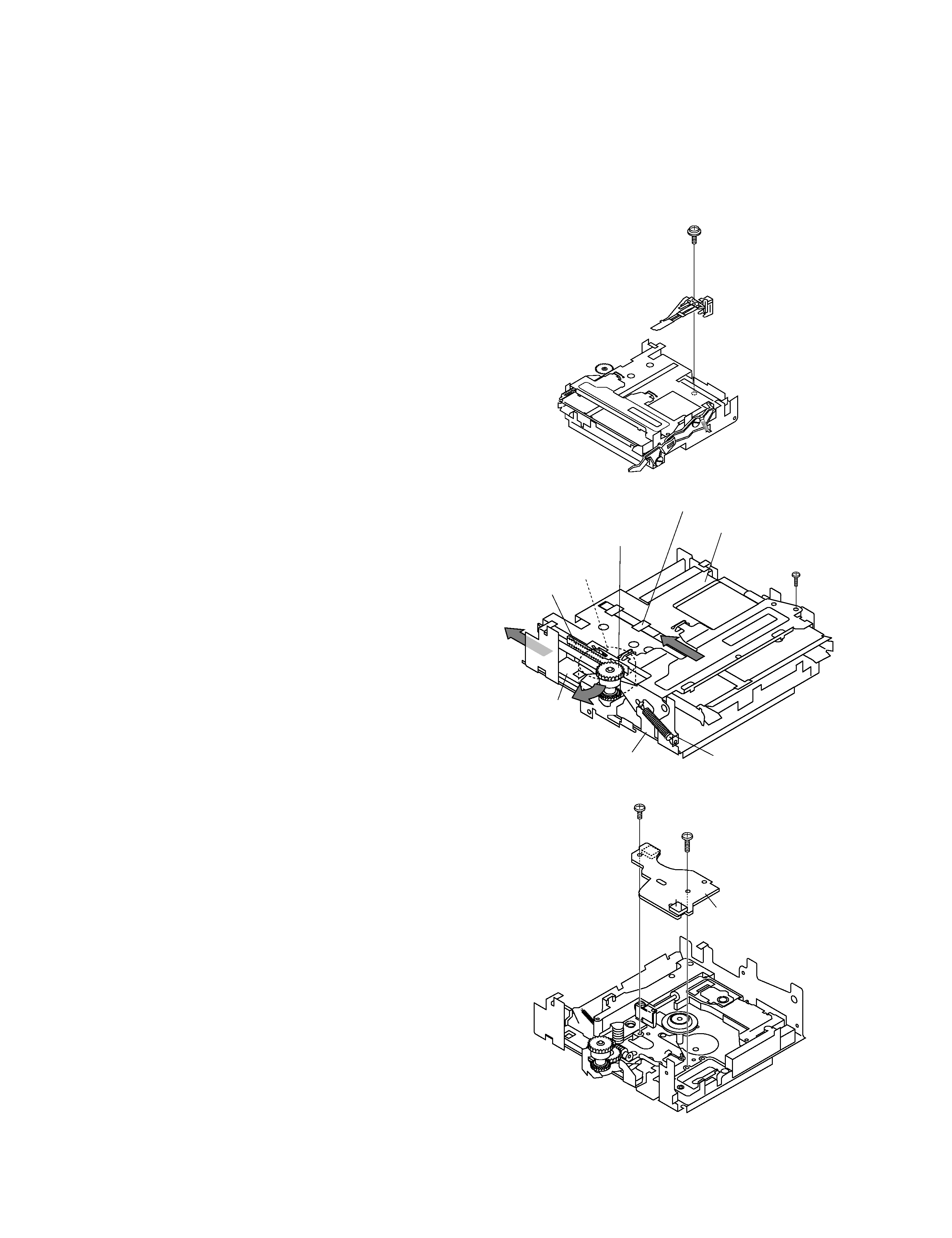
REMOVING AND REINSTALLING THE MAIN PARTS
MD MECHANISM SECTION
Perform steps 1 to 3 of the disassembly method to remove the
MD mechanism.
How to remove the magnetic head
(See Fig. 10-1)
1. Remove the screws (A1) x 1 pc.
10
Caution:
Take utmost care so that the magnetic head is not damaged
when it is mounted.
How to remove the cartridge holder
(See Fig. 10-2)
1. Open the roller arm lever in the arrow direction, and lower
the clamper lever to the rear side.
2. Apply +5V to the red line side of blue connector of loading
motor, push the rack gear in the arrow direction to move the
cam plate lever until tick is heard.
3. Remove the screw (B1) x1 pc., and the spring (B2) x1 pc.,
fitted to the holder arm, and shift the cartridge holder to the
left side to remove it.
How to remove the mechanism switch PWB
(See Fig. 10-3)
1. Remove the screws (C1) x 2 pcs., and remove the mecha-
nism switch PWB.
Figure 10-1
Figure 10-2
Figure 10-3
MD Mechanism
(A1)x1
ø1.7x5mm
Magnetic Head
Slider Lever
Cartridge Holder
Clampa Lever
Lack Gear
Roller Arm Lever
Loading Motor
Cam Plate Lever
(B1) x1
Ø1.7x5mm
(B2) x1
(C1)x1
Ø1.7x3mm
(C1)x1
Ø1.7x9.5mm
MD Mechanism
Switch PWB
DM-3090
5
DISASSEMBLY FOR REPAIR
DM-3090(K) COVER 97.11.29 0:18 AM y[W 10