STEREO INTEGRATED AMPLIFIER/TUNER
C-V751
SERVICE MANUAL
© 1999-8/B51-5566-00 (K/K) 1992
70%
Caution : No connection of ground line if disassemble the unit.
Please connect the ground line on rear panel, PCBs, Chassis and some
others.
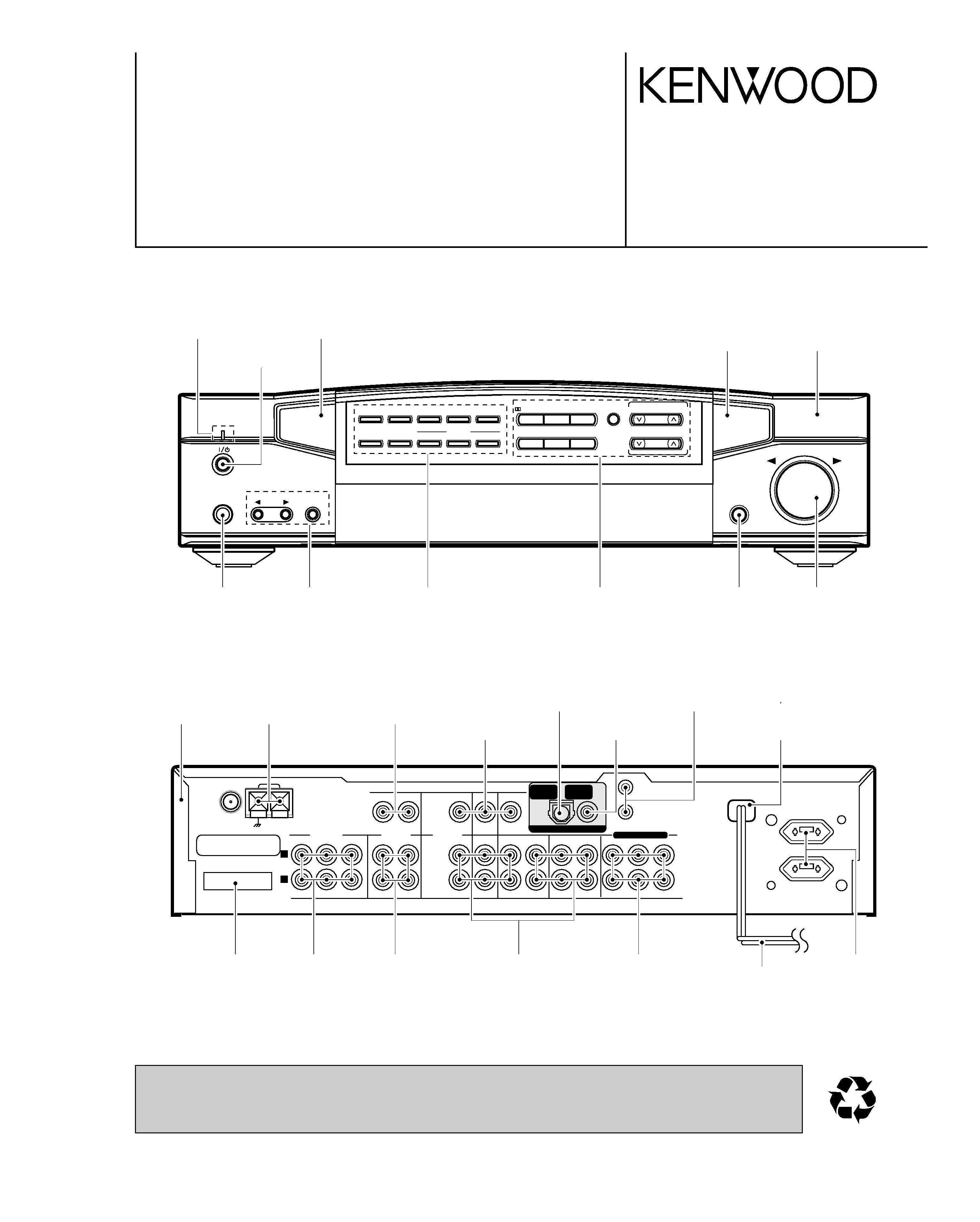
ON/STANDBY
PHONES
INPUT
TAPE 2
/ MONITOR
VOLUME CONTROL
DOWN
UP
DIGITAL
REC
TIMER
MODE
RDS
PTY
DISPLAY
CLOCK
TA/NEWS
DTS
A.MEMO
AUTO
BAND
TUNING
PTY SELECT
LISTEN
MODE
MULTI.CONTROL
LEVEL
OPEN/CLOSE
SET UP
SOUND INPUT MODE
DIGITAL
CIRCLE
SURROUND
TIMER
SET
ANTENNA
AM
FM 75
GND
CONNECT
WITH
POWER AMPLIFIER
UNSWITCHED
SYSTEM
CONTROL
FRONT
SURROUND CENTER
PRE OUT
SUB WOOFER
L
R
REC
PLAY
REC
PLAY
PLAY
PLAY
PLAY
PLAY
DVD/
6CH.INPUT
MONITOR
OUT
REC
PLAY
REC
VIDEO 1
VIDEO 2
VIDEO
DIGITAL IN
FRONT
SURROUND CENTER
SUB WOOFER
CD
MD/TAPE1
TAPE 2/MON
CD
(OPTICAL 1)
DVD
(COAXAL)
DVD/6CH.INPUT
DIGITAL IN
Panel
(A60-1686-01)
Front glass
(B10-2351-14)
Phone jack
(E11-0280-05)
Knob
(K29-6665-02)
Knob
(K29-6666-12)
Knob
(K29-7591-02)
Knob
(K29-6665-02)
Knob
(K29-6660-04)
Knob
(K29-6665-02)
Metallic cabinet
(A01-3702-01)
Lock terminal board
(E70-0052-05)
Phono jack
(E63-0094-05)
Phono jack
(E63-0199-05)
Power cord bushing
(J42-0083-05)
Rectangular receptacle
(E58-0018-05)
Phono jack
(E63-1084-05)
Phono jack
(E63-0136-15)
Phono jack(6P)x2
(E63-0139-15)
Phono jack
(E63-1084-05)
AC power cord *
(E30-)
AC outlet *
(E03-)
Phono jack
(E63-0093-05)
Optical receiving module
(W02-1181-05)
Miniature phone jack
(E11-0293-05)
* Refer to parts list on page 33.
Indicator
(B12-0311-04)
Front glass
(B10-2350-14)
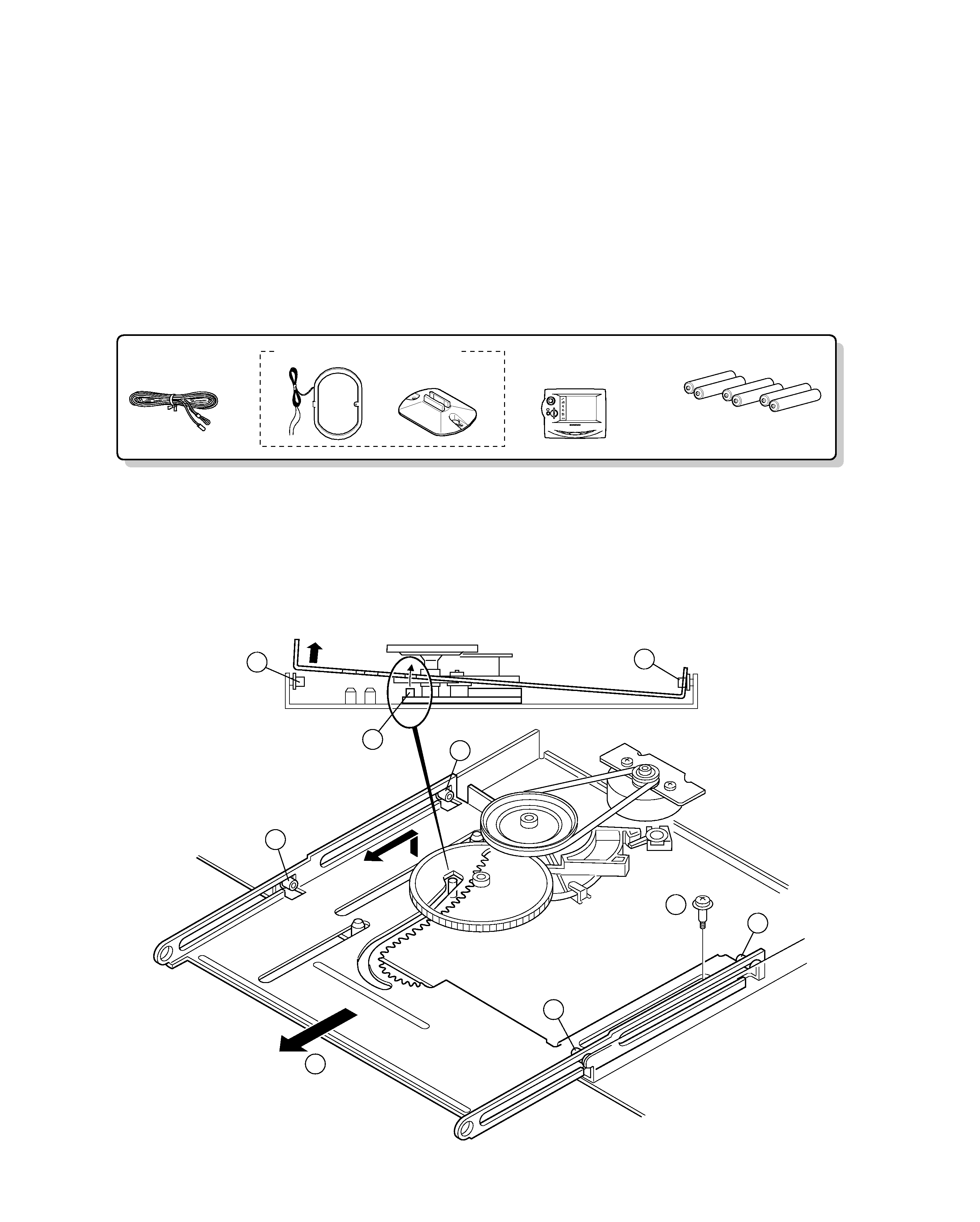
Batteries (R06/AA) (6)
FM indoor antenna (1)
(T90-0841-05)
AM loop antenna (1) (T90-0833-05)
Loop antenna stand (1)
Remote control assy
GRC-700 (1)
(A70-1300-05)
Battery cover(A09-1139-08)
ENTER
V
O
L
U
M
E
UP
DOWN
CONFIRM
ON/STANDBY
CONTRAST
Backlight
e
d
i t
m
o
v i
e
m
u
s i c
s
o
u
n d
li
s
te
n
m o d e
S
le
e p
C-V751
2
CONTENTS / ACCESSORIES
DISASSEMBLY FOR REPAIR
CONTENTS / ACCESSORIES .................................. 2
DISASSEMBLY FOR REPAIR....................................2
CIRCUIT DESCRIPTION ............................................3
ADJUSTMENT ............................................................7
WIRING DIAGRAM .....................................................8
PC BOARD ................................................................ 9
SCHEMATIC DIAGRAM .......................................... 15
EXPLODED VIEW ....................................................32
PARTS LIST..............................................................33
PARTS DESCRIPTIONS ..........................................39
SPECIFICATIONS ......................................Back cover
Contents
Accessories
1. Remove the 1 screw (
1), Then pull the slider (2) till last
2. While raise the slider of left side, remove the slider from
the bosses (
3,4)
1
3
4
4
4
4
4
4
2
x2
x2
C-V751
3
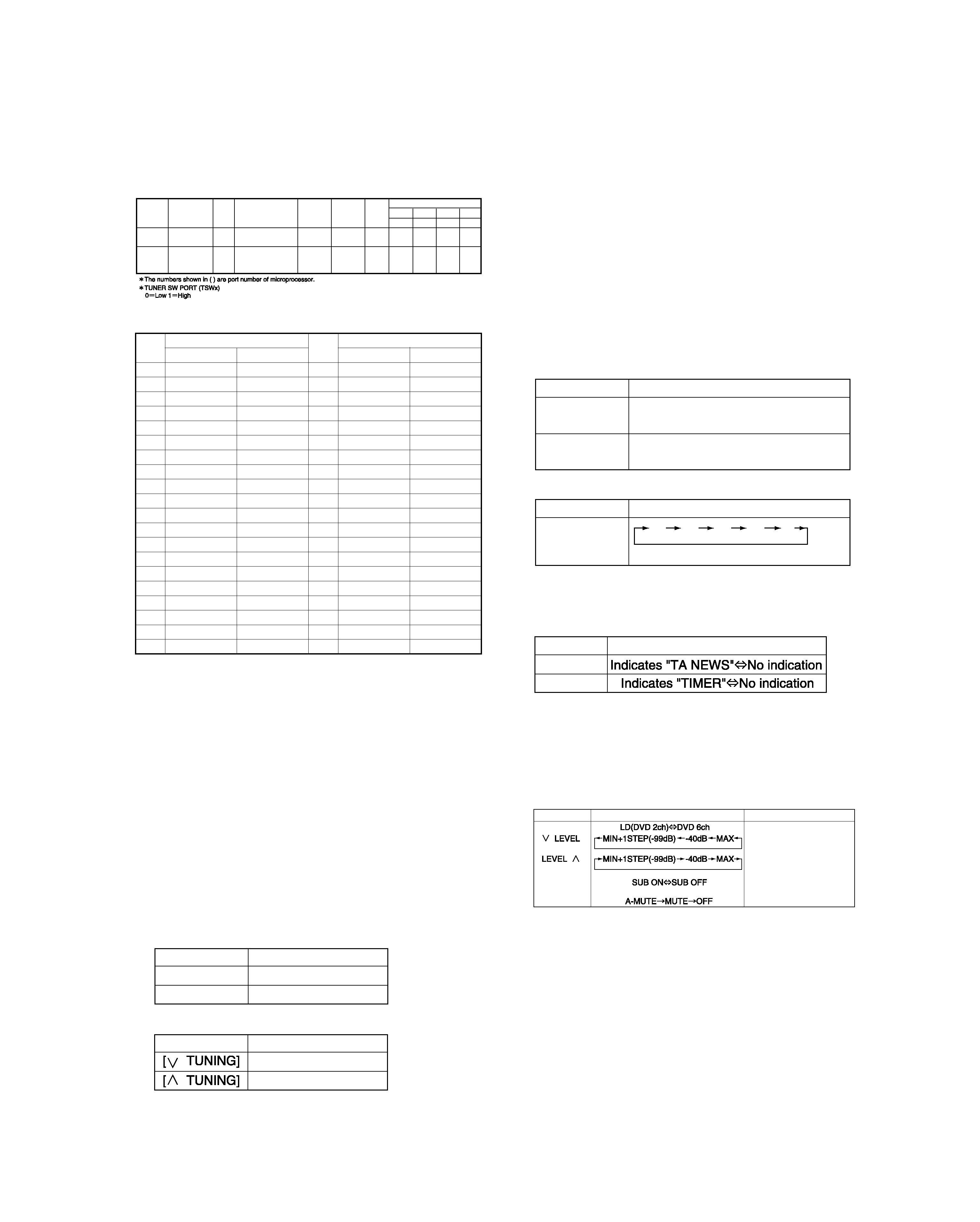
CIRCUIT DESCRIPTION
DESTIN-
ATION
u-COM
DESTINATION
BAND
RECEIVING
FREQUENCY
RANGE
CHANNEL
SPACE
IF
PLL
TUNER SW
TSW4
TSW3 TSW2
TSW1
(22)
(21)
(20)
(19)
E/X
E3
RDS
FM
AM
87.5MHz~108.0MHz
531kHz~1602kHz
50kHz
9kHz
+10.7MHz
+450kHz
25kHz
9kHz
010
1
T
E4
LW
RDS
FM
MW
LW
87.5MHz~108.0MHz
531kHz~1602kHz
153kHz~279kHz
50kHz
9kHz
9kHz
+10.7MHz
+450kHz
+450kHz
25kHz
9kHz
9kHz
011
0
FREQUENCY
FREQUENCY
M.ch
E/X
T
M.ch
E/X
T
1
FM
98.0MHz
FM
98.0MHz
21
AM
531kHz LW
270kHz
2
FM
87.5MHz
FM
87.5MHz
22
FM
87.5MHz LW
216kHz
3
FM
89.1MHz
FM
89.1MHz
23
FM
87.5MHz LW
162kHz
4
FM 108.0MHz
FM 108.0MHz
24
FM
87.5MHz
FM
87.5MHz
5
FM
90.0MHz
FM
90.0MHz
25
FM
87.5MHz
FM
87.5MHz
6
FM
87.5MHz
FM
87.5MHz
26
FM
87.5MHz LW
279kHz
7
FM
87.5MHz
FM
87.5MHz
27
FM
87.5MHz LW
270kHz
8
FM
87.5MHz AM 1602kHz
28
FM
87.5MHz LW
216kHz
9
AM 1602kHz
AM 1440kHz
29
FM
87.5MHz LW
162kHz
10
AM
999kHz
AM
999kHz
30
FM 106.0MHz
LW
153kHz
11
AM
630kHz LW
216kHz
31
FM
87.5MHz
FM
87.5MHz
12
AM 1440kHz
AM
630kHz
32
FM
87.5MHz
FM
87.5MHz
13
FM 106.0MHz
FM 106.0MHz
33
FM
87.5MHz
FM
87.5MHz
14
AM
531kHz
AM
531kHz
34
FM
87.5MHz LW
279kHz
15
FM
87.5MHz
FM
87.5MHz
35
FM
87.5MHz LW
270kHz
16
FM
98.0MHz
FM
98.0MHz
36
FM
87.5MHz LW
216kHz
17
FM
98.5MHz
FM
98.5MHz
37
FM
87.5MHz LW
162kHz
18
FM
87.5MHz AM
531kHz
38
FM
87.5MHz
FM 108.0MHz
19
AM
990kHz
AM
990kHz
39
FM 108.0MHz
AM
999kHz
20
FM
97.7MHz LW
279kHz
40
AM
999kHz LW
216kHz
1. Conditions according to the destination
TUNER destination table
2. Contents of tuner preset memory
· Sub-clock oscillation diagnosis function The oscillation
diagnosis(existence oscillation and measurement of peri-
od) of a sub-clock is performed before the test mode is
entered. If the diagnosis result is OK, the system is
entered the test mode.
If the diagnosis result is NG, the oscillation of the sub-
clock diagnosed again. If the result is OK, the system
enters the test mode. If the diagnosis result is continuous-
ly NG 5 times, the system stops with ERR1 and ERR2
displayed.
3-5 Tuner test mode
(When selector is set to TUNER.)
· P.CALL of preset channel.
· S level indication.
Set the TUNER ATT to ON/OFF and display the S level in
hexadecimal when the [PTY] key is pressed.
· Indication of FL for TA NEWS and TIMER.
3-6 AMP test mode
(When the selector is set to positions other then TUNER.)
During the test mode, it can be operated in a special
manner that is different from an ordinary operation by
using the keys on the remote control or the main body,
specifically as shown in the following table.
KEYS
FUNCTION or FL INDICATION
REMARKS
AUTO
One touch settings.
Volume value.
Volume value.
A.MEMO
Sub mute ON/OFF operation
and FL indication.(except for
stereo mode)
TIMER MODE
One touch settings.
KEY
FL INDICATION
[TA/NEWS]
[DISPLAY]
KEYS
OPERATION
[TIMER SET]
Increments the P. CALL every time
this key is pressed.
[TIMER MODE]
Decrements the P. CALL every time
this key is pressed.
KEY
OPERATION
[DIGITAL REC]
Selects the P.CALL steps cyclically.
10
20
30
40
01
3. Test mode
3-1 Entering the test mode
· Turn on the power while pressing the [OPEN/CLOSE] key.
· The test mode gets started while the power is turned on
after that,all the FLs will light up and the panel opens.
· Sub-clock oscillation diagnosis function is entered by
pressing the [DIGITAL REC MODE] key in the all FL light-
ing mode.
3-2 Canceling the test mode
The system is initialized and the test mode is canceled
when the AC power is turned off.
3-3 Initializing
The system is initialized when the power is turned on
while pressing the [ON STANDBY] key.
3-4 Contents of the test mode
· Key operation in all FL lighting mode.
· All FL lighting off mode.
KEYS
OPERATION
All FL lighting off.
Normal indication.
KEYS
OPERATION
[AUTO]
Green LED lights on.
[A.MEMO]
Red LED lights on.
· Selection of P. CALL steps.

C-V751
4
CIRCUIT DESCRIPTION
Pin No.
Pin Name
I/O Description
ACTIVE
HL
1
AMUTE
O
Audio muting control.
Mute:ON
Mute:OFF
2
POWER
O
Power ON/OFF relay control.
Power:ON
Power:OFF
3
POWER
O
Power amplifier relay control.
Power:ON
Power:OFF
4
F RLY
O
Front speaker relay control.
Relay:ON
Relay:OFF
5
C RLY
O
Relay control of center,surround and SW woofer.
Relay:ON
Relay:OFF
6
S RLY
O
Rear speaker relay control.
Mute:ON
Mute:OFF
7
+3dB
O
+3dB attenuation control for super woofer.
ATT:ON
ATT:OFF
8
20dB
O
+20dB attenuation control for volume control.
20dB gain
9
PROTECTION
I
Detection terminal of protection signal.
PRT:ON
10
S DATA
I/O Serial communication data signal.
11
S BUSY
I/O Serial communication busy signal.
12
T MUTE
O
Muting control of audio signal for tuner.
Mute:ON
Mute:OFF
13
PLL CLK
O
Clock output of PLL IC for tuner.
14
PLL DATA
O
Data output of PLL IC for tuner.
15
PLL CE
O
Chip enable of PLL IC for tuner.
16
PLL DO
I
Data input from PLL IC.
17
SD
I
Syntony signal input of tuner.
18
STEREO
I
Stereo signal input.
19~22
T SW1~4
I
Discrimination of the tuner destination.
23
M OPEN
O
Control terminal of motor driver.(Motor CW î Door open)
24
M CLOSE
O
Control terminal of motor driver.(Motor CCW î Door close)
25
OPEN SW
I
Detection port of door open/close switch.
Open
26
CLOSE SW
I
Detection port of door open/close switch.
Close
27
DIG. H
O
Port for digital input.
28
RWR
I
Reading of interactive remote control data.
H:End of reading data.
29
ENB
I
Permission of transmission .
Permission
30
REQ
O
Request of transmission.
No Request
31~38
R DATA1~8
O
Data output to remote control microprocessor.
39
CE
I
Chip enable.
40
RST
I
Reset signal input.
41
VSS
-
Ground.
42
XTAL
-
16MHz main oscillator.
43
EXTAL
I
16MHz main oscillator.
44
SEL STB2
O
Unused.
45
SEL STB1
O
Strobe output to selector IC.
46
SELCLK
O
Clock output to selector IC.
47
SEL DT
O
Data output to selector IC.
48~50
VIDEO1~3
O
Control port for video selector.
51
DSP RST2
O
Reset signal output to DSP.
52
AVSS
-
Ground.
53
AVREF
-
Connected to VCC.
54
AVDD
-
Power supply(+5.0V).
55
VOL CLK
O
Clock output to electric volume(IC28).
56
VOL DATA
O
Data output to electric volume(IC28).
57
VOL LATCH
O
Latch output to electric volume(IC28).
58
CODEC RST
O
Reset port to A/D,D/A converter.
59
-
-
Unused.
60
RDS SLEVEL
I
Signal level input from RDS decoder.
61
DOOR KEY
I
Detection port of door key(S16) .
62
POW KEY
I
Detection port of power key(S3).
63
OESL
O
Switching the output enable.
64
AUDIO
I
Detection port of audio.
4. Microprocessor: CXP740010-107Q(X08,IC16)
4-1 Port description of microprocessor
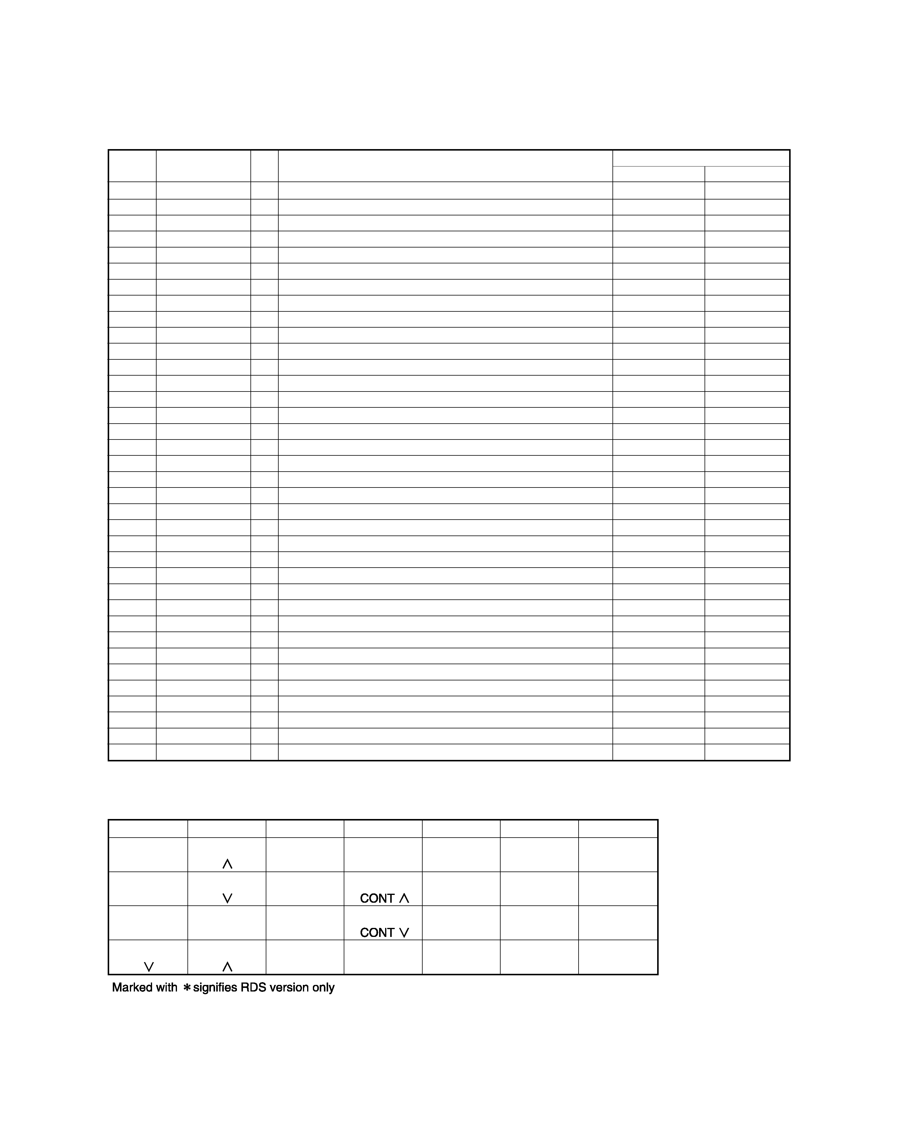
5
C-V751
CIRCUIT DESCRIPTION
KS1(15pin)
KS2(16pin)
KS3(17pin)
KS4(18pin)
KS5(19pin)
KS6(20pin)
KS7(21pin)
TAPE2
MONITOR
INPUT
AUTO
-
*TA/NEWS/
INFO.
SRS
-
-
INPUT
BAND
LEVEL
*PTY
DTS
-
TIMER
MODE
TIMER
SET
AUTO
MEMORY
LEVEL
*DISPLAY
DOLBY.D
INPUT
MODE
TUNING
TUNING
D.REC
MODE
SET UP
TIMER
CLOCK
SOUND
Pin No.
Pin Name
I/O Description
ACTIVE
HL
65
ERR
I
Detection port of error.
ERROR
66
AC3
I
Detection port of dolby digital.
67
FREQ1
I
Detection port 1 of sampling frequency.
68
FREQ0
I
Detection port 0 of sampling frequency.
69
CODEC DIN
I
Data input.
70
ABQOT2
I/O ABOOT output/INTREQ input port.
71
ABQOT SEL1
O
Switching the power supply of ABOOT/INTREQ(IC6).
72
ABQOT SEL2
O
Switching the power supply of ABOOT/INTREQ(IC5).
73
DSP CS
O
CS output to IC33.
74
ADD1
O
External ROM(IC2) address1.
75
CODEC CS
O
CS output to IC15.
76
DSP RST1
O
Reset output to DSP(IC6).
77
RDS DATA
I
Data input from RDS decoder.
78
RDS CLK
I
Clock input from RDS decoder.
79
DSP D1
I
Data input from IC15.
80
DSP DO
O
Data output to IC6.
81
DSP/CO CLK
O
Clock output to IC15 and IC6.
82
ABOOT1
I/O ABOOT output/INTREQ input port.
83
HP. DETECT
I
Detection port of headphones.
H/P ON
84
HP. MUTE
O
Muting control of audio signal for headphones.
Mute OFF
Mute ON
85
REMOCON
I
Input port of remote control signal.
86
TEX
I
Sub clock(32.768kHz) input.
87
TX
I
Sub clock(32.768kHz) input.
88
VSS
-
Ground.
89
VDD
-
Power supply(+5.0V).
90
NC
-
Unused.
91
ADD2
O
External ROM(IC2) address2.
92
ADD3
O
External ROM(IC2) address3.
93
LED R
O
Standby LED (red) control.
94
LED G
O
Standby LED (green) control.
95
ENC CCW
I
Pulse input from volume encoder.
96
ENC CW
I
Pulse input from volume encoder.
97
FL DI
O
Data output to FL driver.
98
FL DO
I
Data input from FL driver.
99
FL CLK
O
Clock output to FL driver.
100
FL STB
O
Strobe output to FL driver.
4-2 Key matrix
The numbers shown in ( ) are port number of FL driver(X14,IC1).
W&g
?W&@g
W&@@g
.Y@@g
@@g
@@g
@@g
@@g
@@g
@@g
@@g
@@g
@@g
@@g
@@g
@@@@@@f
?
?
?
?
?
?
?
?
?@@@@@@@@6K?e?
?@@?eI'@@e?
?@@?e?N@@L??
?@@?f@@1??
?@@?f@@@??
?@@?f@@5??
?@@?e?J@@H??
?@@?eO&@@e?
?@@@@@@0M?e?
?@@?h?
?@@?h?
?@@?h?
?@@?h?
?@@?h?
?@@?h?
?@@@@@@?g?
?
?
?
?
?
?
?
O2@@6Kf
?@@(MI'@@?e
J@(YeV'@Le
7@H?e?N@1e
@@g@@e
@@g@@e
3@L?e?J@@e
N@)XeW&@@e
?@@)KO&@@@e
I4@@0Y@5e
?J@He
W&5?e
?W&(Y?e
O&(Yf
O2@0Y?f
?@@0M?g
O2@@6Kf
?@@(MI'@@?e
J@(YeV'@Le
7@H?e?N@1e
@@g@@e
@@g@@e
3@L?e?J@@e
N@)XeW&@@e
?@@)KO&@@@e
I4@@0Y@5e
?J@He
W&5?e
?W&(Y?e
O&(Yf
O2@0Y?f
?@@0M?g
?@@?e
?@@?e
W&g
?W&@g
W&@@g
.Y@@g
@@g
@@g
@@g
@@g
@@g
@@g
@@g
@@g
@@g
@@g
@@g
@@@@@@f
W&g
?W&@g
W&@@g
.Y@@g
@@g
@@g
@@g
@@g
@@g
@@g
@@g
@@g
@@g
@@g
@@g
@@@@@@f
?@@?e
?@@?e
W&g
?W&@g
W&@@g
.Y@@g
@@g
@@g
@@g
@@g
@@g
@@g
@@g
@@g
@@g
@@g
@@g
@@@@@@f
W&g
?W&@g
W&@@g
.Y@@g
@@g
@@g
@@g
@@g
@@g
@@g
@@g
@@g
@@g
@@g
@@g
@@@@@@f
W&g
?W&@g
W&@@g
.Y@@g
@@g
@@g
@@g
@@g
@@g
@@g
@@g
@@g
@@g
@@g
@@g
@@@@@@f
?
?
?
?
?
?
?
?
?
?
?
?
?
?@@?e?
?@@?e?
?
?
?
?
?
?
?
?@@?e?
?@@?e?
?
?
?
?
?
?
?
W&f
?W&@f
W&@@f
?W&@@@f
W&(Y@@f
?W&(Y?@@f
W&(Ye@@f
?W&(Y?e@@f
?7@Yf@@f
?@@@@@@@@@@@e
?@@@@@@@@@@@e
@@f
@@f
@@f
@@f
@@f
W&f
?W&@f
W&@@f
?W&@@@f
W&(Y@@f
?W&(Y?@@f
W&(Ye@@f
?W&(Y?e@@f
?7@Yf@@f
?@@@@@@@@@@@e
?@@@@@@@@@@@e
@@f
@@f
@@f
@@f
@@f
?
?
?
?
?
?
?
?
?@h?
?@L?g?
J@1?g?
7@@Lg?
?J(Y@1g?
?7H?3@L?f?
J5eN@1?f?
7He?3@Lf?
?J5?e?N@1f?
?7Y?f@@L?e?
J@@@@@@@@@1?e?
7<g?@@?e?
?J5?g?3@Le?
?7H?g?N@1e?
?@he@@e?
?@@@@@f?@@@@@@@?
?
?
?
?
?
?
?
?
?
?
?
?
?
?
?
@@@@he@@@@@??
@@L?g?J@@@?e?
@@1?g?7Y@@?e?
@@@Lg?@?@@?e?
@?@1gJ5?@@?e?
@?3@L?f7H?@@?e?
@?N@1?f@??@@?e?
@??3@Le?J5??@@?e?
@??N@1e?7H??@@?e?
@?e3@L??@e?@@?e?
@?eN@1?J5e?@@?e?
@?e?3@W&He?@@?e?
@?e?N@@@?e?@@?e?
@?f3@5?e?@@?e?
@?fN@H?e?@@?e?
@@@@@?e?@e?@@@@@@??
?
?
?
?
?
?
?
W26Xf
7<B1f
3=C5f
W2@@6XfV40Yf
?W&(MI')X?he
W&(YeV')Xhe
?W&(Y?e?V')X?h
W&(YgV')Xh
@?&@H?g?V')X?g
3@@5heV')Xg
V40Yhe?V')K?f
V'@6X?e
?V'@)Xe
V'@1e
?V4@e
?O26X?e
?@K?f?O2@@@@@@@@@1?e
?3@@@@@@@@0Mg?I@?e
?V40M?
@@6Khe'6X?e
?I'@@?f?'6XV'1?e
V4@?f?V'1?V'?e
V'g
?@@6K?
I'@@hfW.f
?V4@he?W&Hf
W&5?f
?W&(Y?f
W&(Yg
?W&(Y?g
O&(Yh
W2@(Y?h
?O&@0Yhe
?O2@(Mhf
?@KO2@@0Y?hf
?3@@@0M?hg
?V40M?
W&g
?W&@g
W&@@g
.Y@@g
@@g
@@g
@@g
@@g
@@g
@@g
@@g
@@g
@@g
@@g
@@g
@@@@@@f