STEREO INTEGRATED AMPLIFIER/TUNER
C-V100/V150/V300/V350
SERVICE MANUAL
© 1997-6/B51-5323--00 (K/K) 3676
ON/STANDBY
PHONES
INPUT
TAPE 2
(MONITOR)
CLOCK
TIMER
MODE
TIMER
SET
AUTO A.MEMO
BAND
TUNING
MODE
MULTI. CONTROL
LEVEL
VOLUME CONTROL
DOWN
UP
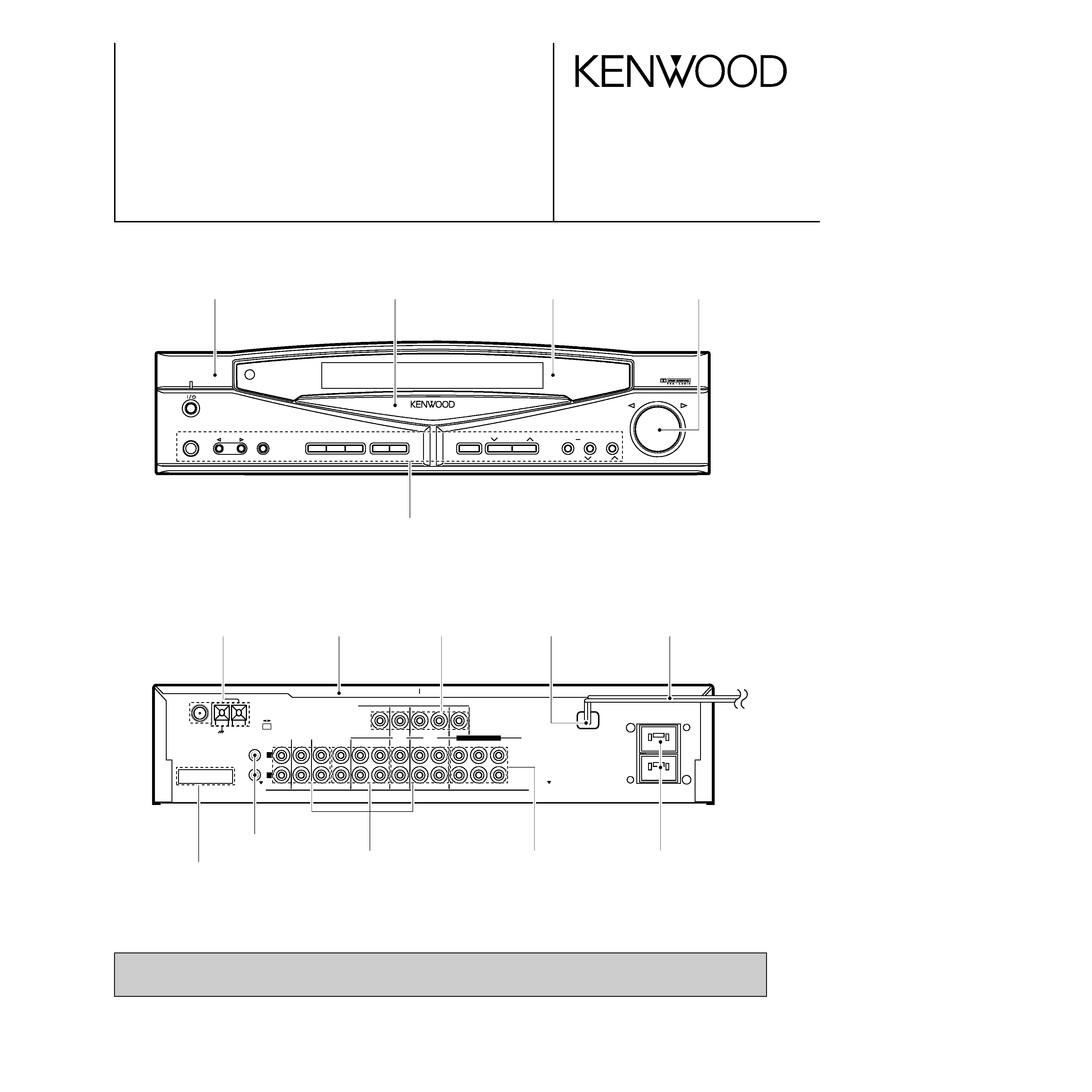
ANTENNA
AM
FM 75
GND
CONNECT WITH
POWER AMPLIFIER
SYSTEM
CONTROL
CD
AUX
TAPE 1/ MD
IN
IN
REC
PLAY
IN
TAPE 2
(MONITOR)
AUDIO
FRONT
REC
REC
PLAY
PLAY
MONITOR
OUT
SURROUND
VIDEO
CENTER
SUBWOOFER
UNSWITCHED
LD
/DVD
VCR
L
R
DVD 6CH.INPUT
DIGITAL IN DIGITAL IN
FM 50kHz
AM 9kHz
FM
100kHz
AM 10kHz
50
µs
75
µs
DE-
EMPHASIS
CHANNEL
SPACE
Dressing panel
(A21-1952-03)
Panel *
(A60-)
Lock terminal board
(E70-0052-05)
Phono jack
(E63-0163-05)
Metallic cabinet
(A01-3432-01)
Power cord busing
(J42-0083-05)
AC power cord *
(E30-)
Miniature phone jack (2P)
(E11-0293-05)
Phono jack
(E63-0139-15)x3
Phono jack *
(E63-0111-05)
C-V300/C-V350 only
AC outlet *
(E03-)
Knob *
(K29-)
Caution : No connection of ground line if disassemble the unit.
Please connect the ground line on rear panel, PCBs, Chassis and some others.
Front glass *
(B10-)
Knob
(K29-6660-04)
Rectangular receptacle
(E58-0018-05)
Illustration is C-V100.
* Refer to parts list on page 33.
CONTENTS / ACCESSORIES
C-V100/V150/V300/V350
2
Contents
CONTENTS / ACCESSORIES ....................................2
CONTROLS .................................................................3
DISASSEMBLY FOR REPAIR .....................................7
BLOCK DIAGRAM .......................................................8
CIRCUIT DESCRIPTION .............................................9
ADJUSTMENT ...........................................................14
PC BOARD ................................................................15
SCHEMATIC DIAGRAM ............................................23
EXPLODED VIEW .....................................................41
PARTS LIST...............................................................43
SPECIFICATIONS .....................................................54
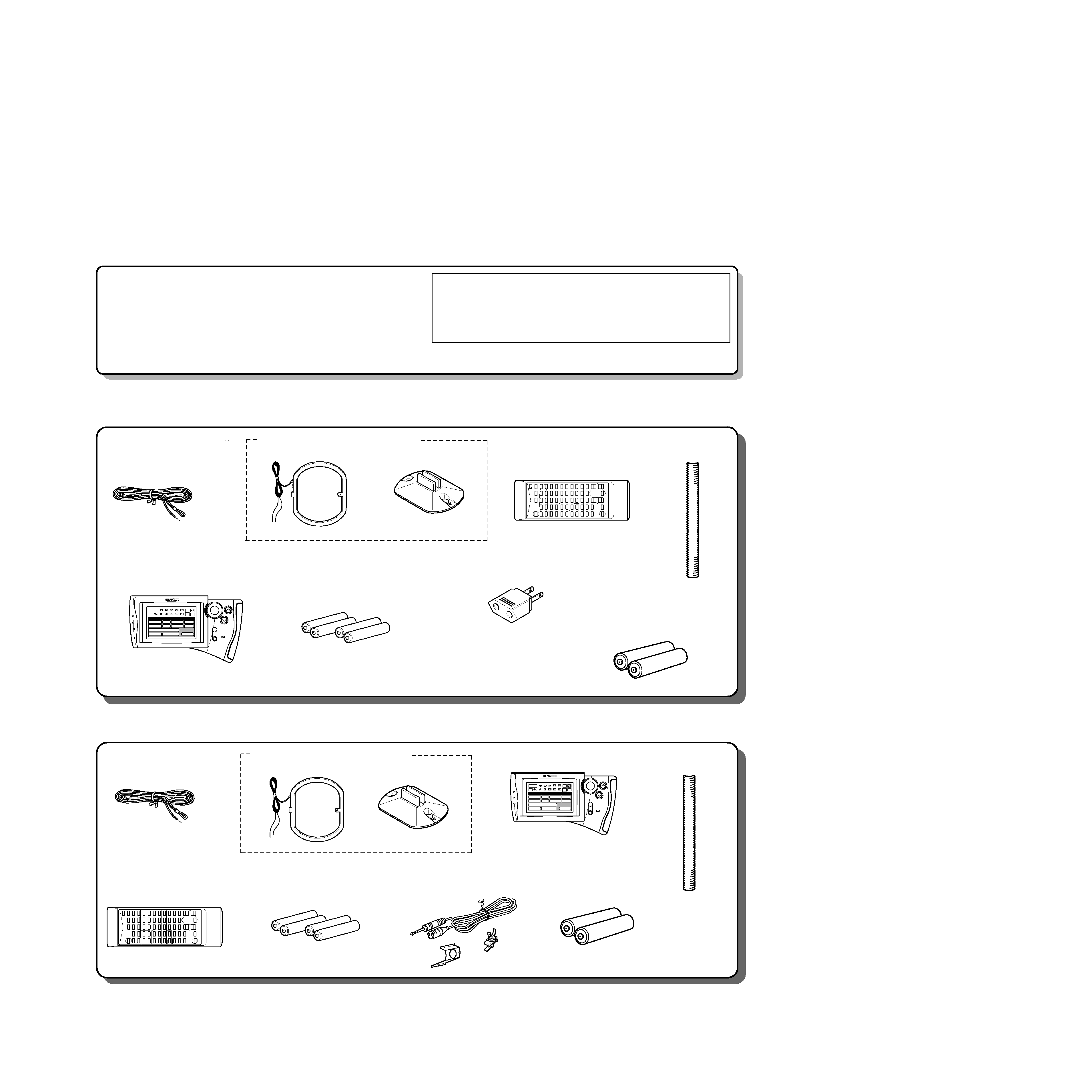
FM indoor antenna(1)
(T90-0809-05): MICX type
(T90-0810-05): KPY type
AM loop antenna(1) (T90-0820-05)
Loop antenna stand(1)
Remote control unit(1) *
(C-V100)
(Except U.S.A. and Canada)
Cable tidy(2)
(F07-0102-04)
Graphical Remote Control unit(1) *
(C-V300)
(C-V100,only U.S.A. and Canada) *
Batteries(R03/AAA) (4)
(C-V300)
(C-V100,only U.S.A. and Canada)
Batteries(R6/AA) (2)
(C-V100)
(Except U.S.A. and Cana-
* Use to adapt the plug on
the power cord to the shape
of the wall outlet.(Accessory
only for regions where use is
necessary)
ON/STANDBY
MUTE
VOLUME
ENTER
Setup
DVD/6ch Input
Sound Speaker
C D
Sat.
Tape1
Cable
Reset
VCR1
VCR2
L D
T V
Confirm
Set Up
Return
Input
Source
Main Menu
TapeA
TapeB
Tape1
LD
Tuner
CD
VCR2
VCR1
TV
Sat.
Cable
FM indoor antenna(1)
(T90-0809-05): MICX type
(T90-0810-05): ET type
AM loop antenna(1) (T90-0820-05)
Loop antenna stand(1)
Remote control unit(1) *
(C-V150)
Cable tidy(2)
(F07-0102-04)
Graphical Remote Control unit(1) *
(C-V350)
Batteries(R03/AAA) (4)
(C-V350)
Batteries(R6/AA) (2)
(C-V150)
ON/STANDBY
MUTE
VOLUME
ENTER
Setup
DVD/6ch Input
Sound Speaker
C D
Sat.
Tape1
Cable
Reset
VCR1
VCR2
L D
T V
Confirm
Set Up
Return
Input
Source
Main Menu
TapeA
TapeB
Tape1
LD
Tuner
CD
VCR2
VCR1
TV
Sat.
Cable
Microphone(1)
(W01-0935-05)
(Optional with the C-V150)
How to reset the microcomputer
The microcomputer may malfunction (impossibility operation,erro-
neous display,etc.) when the power cord is unplugged and plugged
in again while the unit is in ON mode with the Key pressed or due
to other external causes.In this case,execute the procedure on the
right to reset the microcomputer and return the unit to the normal
condition.
· Resetting the microcomputer clears the memory you entered and
returns in to the initial condition when the unit left the factory.
1 Unplug the power cord from the wall outlet.
2 While pressing and holding the POWER or
(ON/STANDBY)key,plug the AC cord into the wall out-
let again
*AC plug adapter (1)
(E03-0115-05)
Accessories (C-V100/300)
(C-V150/350)
* Refer to parts list on page 33.
CONTROLS
C-V100/V150/V300/V350
3
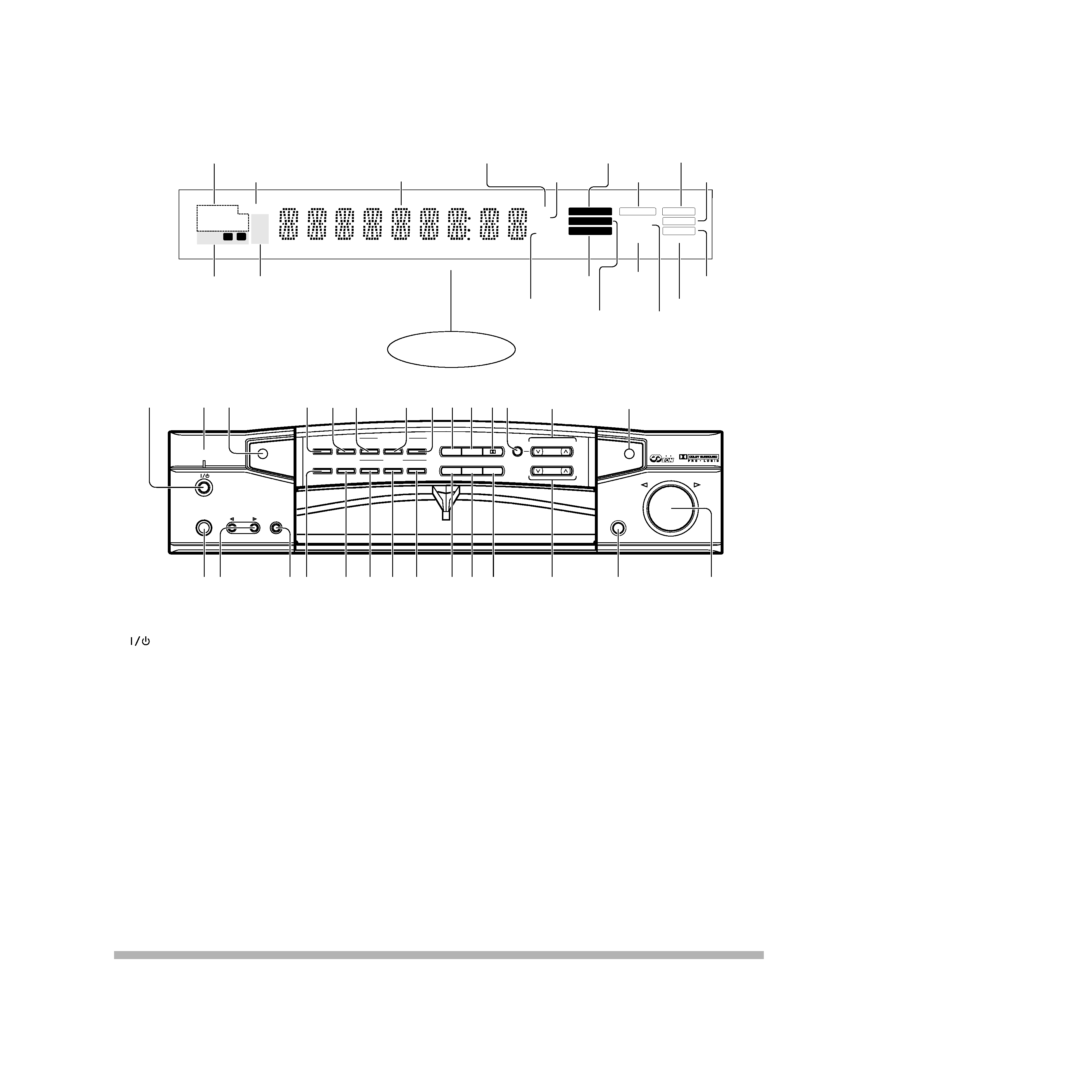
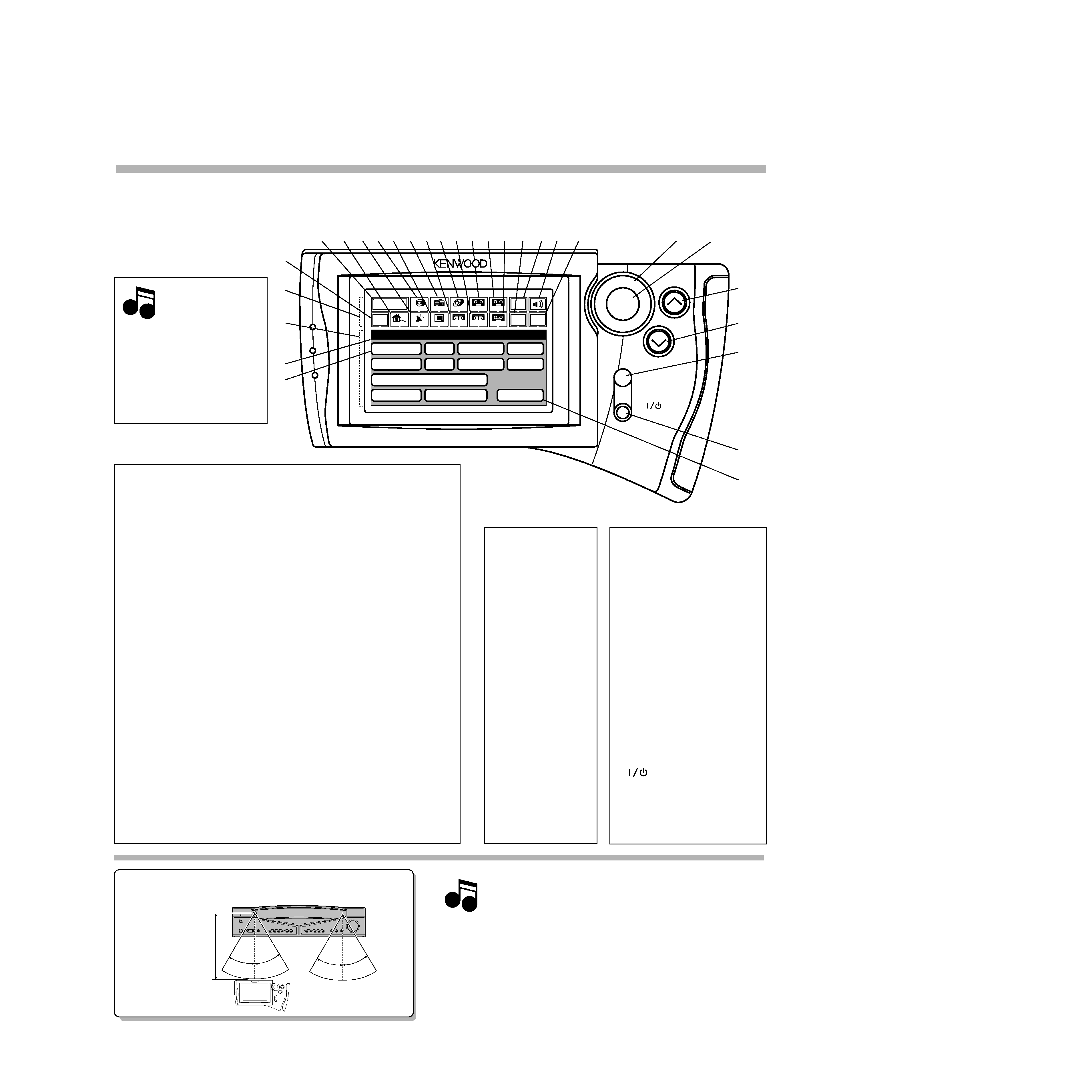
1
(ON/STANDBY) key
Press to switch between ON and STAND-
BY.
2VOICE ACTIVATE indicator
Lights to indicate an occurrence of voice
activation.
3Remote sensor
4TIMER SET key
Press to set the timer function.
5CLOCK key
Press to set the clock.
6VOICE ACTIVATE ON/OFF key
Press to switch the voice-activation opera-
tion ON and OFF.
7VOICE ACTIVATE SET 1 key
Press to record words for use in voice ac-
tivation.
8VOICE ACTIVATE SET 2 key
Press to record words for use in voice ac-
tivation.
9STEREO key
0DSP key
!DOLBY key
@MODE key
Press to switch various setting modes.
#MULTI.CONTROL key
Press to select various setting modes.
$GRC transmitter
Outputs the signals transmitted to the
Graphical Remote Control.
%PHONES jack
For use in headphones listening.
^INPUT SELECTOR key
Press to select the input.
&TAPE 2 (MONITOR) key
For use in monitoring of recording, etc.
*TIMER MODE key
Press to switch the timer modes.
(S.DIRECT key
Press to switch the Source Direct function
which allows to reproduce the source with
a better quality.
)RDS DISPLAY key
Press to switch the RDS display.
¡RDS PTY key
For use during reception of RDS broad-
casting.
TMRDS TA/NEWS/INFO. key
For use during reception of RDS broad-
casting.
£A.MEMO key
Press when using the auto memory func-
tion.
¢AUTO key
Press to select the tuning mode.
The auto tuning or manual tuning mode
can be selected.
The input selection display of a source
can be switched to another by pressing
and holding the AUTO key for more than
2 seconds.
BAND key
Press to switch the broadcasting band.
§TUNING keys (, )
Press to select the radio station to be re-
ceived.
These keys are also used in the clock ad-
justment and timer operations.
¶OPEN/CLOSE key
·VOLUME CONTROL knob
ON/STANDBY
PHONES
INPUT
TAPE 2
(MONITOR)
VOLUME CONTROL
DOWN
UP
AV CONTROL CERTER KC-2
^
2
CLOCK
TIMER
MODE
RDS
PTY
DISPLAY
TIMER
SET
S.DIRECT
ON/OFF
TA/NEWS/INFO.
SET 1
SET 2
VOICE
ACTIVATE
STEREO
DSP
A.MEMO
AUTO
BAND
TUNING
PTY SELECT
MODE
MULTI.CONTROL
LEVEL
·
OPEN/CLOSE
8
4
13
5 6
@
7
0 !
9
#
$
¶
VOICE
ACTIVATE
%
R D S
&*(
¡ TM
)£ ¢
§
AUTO
RDS
EON
PTY
TIMER
NEWS
INFO.
FM
LW
MW
TA
TP
PRO LOGIC
3 STEREO
DSP
TAPE 2
STEREO
TUNED
MUTE
SLEEP
dB
ms
MHz
kHz
1
2
SOURCE
DIRECT
MEMO
The keys which have the same names as the controls on the
remote control unit provide the same functions as them.
MEMORY indicator
RDS indicators
(RDS, TP, TA, EON, PTY, NEWS, INFO.)
Frequency display, input
selector display, preset
channel display, surround
mode display
Decibel indicator
Delay time indicator
DSP indicator
TAPE 2 indicator
AUTO tuning
mode/AUTO stereo
reception indicator
STEREO indicator
TUNED indicator
MUTE indicator
SOURCE DIRECT indicator
SLEEP
TIMER
indicator
PRO LOGIC
indicator
3 STEREO
indicator
Receiving frequency
unit indicators
Display
STANDBY mode indication
While standby mode is indicated, a small amount of power is supplied to the system to back up the memory. In this mode, the system can be
turned ON by remote control.
With this unit, standby mode is indicated by means of the display panel. The system is in standby mode while the clock display is shown.
TIMER
indicators
Broadcast band indi-
cators
CONTROLS
C-V100/V150/V300/V350
4
ON/STANDBY
PHONES
INPUT
TAPE 2
(MONITOR)
CLOCK
TIMER
MODE
TIMER
SET
AUTO A.MEMO
BAND
TUNING
MODE
MULTI. CONTROL
LEVEL
VOLUME CONTROL
DOWN
UP
AUTO
FM
AM
TAPE 2
STEREO
TUNED
MUTE
SLEEP
dB
ms
MHz
kHz
SOURCE
DIRECT
MEMO
ON/STANDBY
TIMER
1
2
DSP
3 STEREO
PRO LOGIC
POWER
5
$
^
8
7
9
!
@
6
0
#%
&
3 4
1 2
*
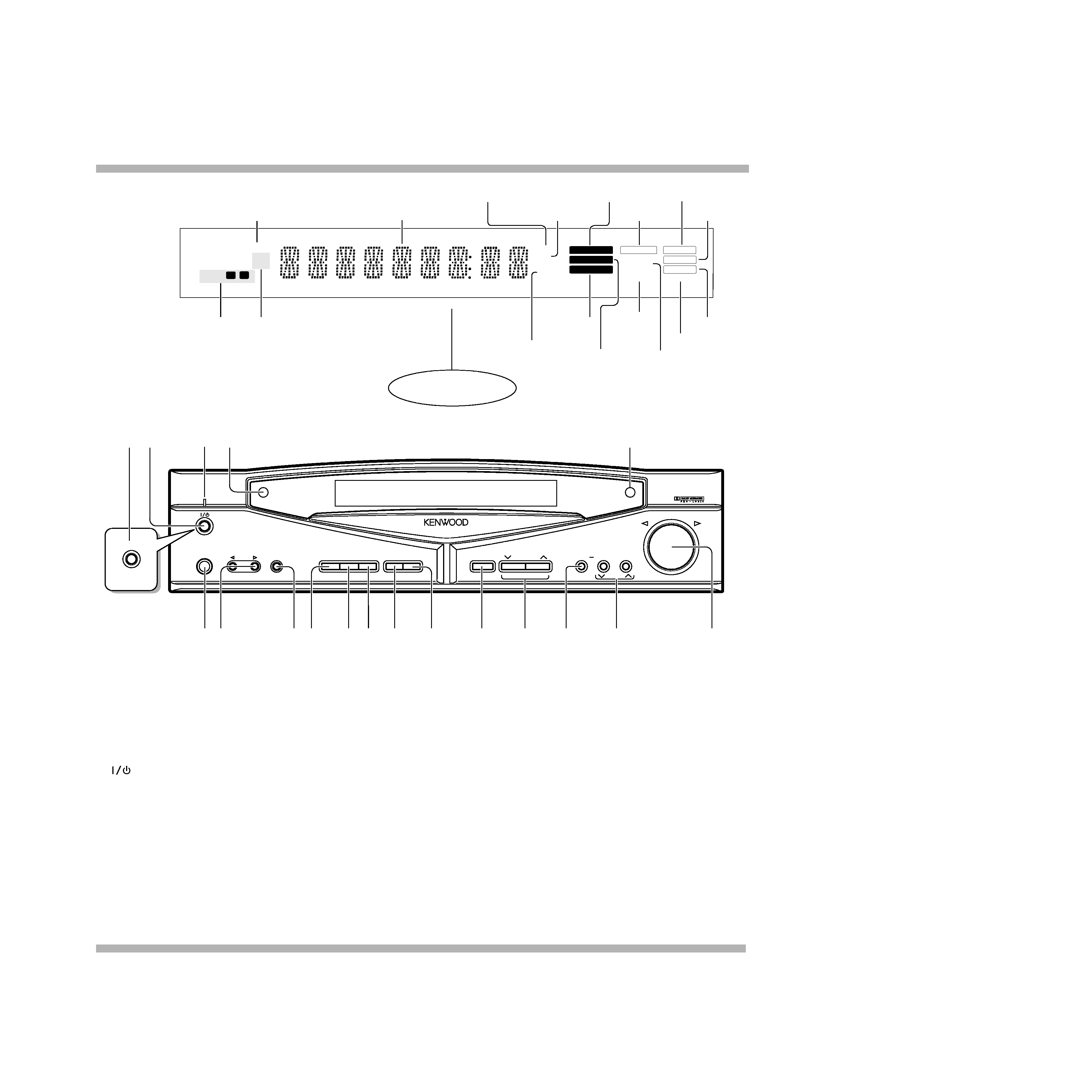
The keys which have the same names as the controls on the
remote control unit provide the same functions as them.
Memory indicator
Frequency display, input
selector display, preset
channel display, surround
mode display
Decibel indicator
Delay time indicator
DSP indicator
TAPE 2 indicator
AUTO tuning mode/AUTO
stereo reception indicator
STEREO indicator
TUNED indicator
MUTE indicator
SOURCE DIRECT indicator
PRO LOGIC
indicator
3 STEREO
indicator
Receiving
frequency unit
indicators
Display
STANDBY mode indication
While standby mode is indicated, a small amount of power is supplied to the system to back up the memory. In this mode, the system can be
turned ON by remote control.
TIMER
indicators
Broadcast band
indicators
SLEEP
TIMER
indicator
For C-V100
1POWER
(ON/STANDBY) key
(U.S.A. and Canada)
Press to switch between ON and STAND-
BY.
2
(ON/STANDBY) key
Press to switch between ON and STAND-
BY.
3STANDBY indicator
4Remote sensor
5PHONES jack
For use in headphones listening.
6INPUT SELECTOR key
Press to select the input.
7TAPE 2 (MONITOR) key
For use in monitoring of recording, etc.
8CLOCK key
Press to set the clock.
9TIMER MODE key
Press to switch the timer modes.
0TIMER SET key
Press to set the timer function.
!AUTO key
Press to select the tuning mode.
The auto tuning or manual tuning mode
can be selected.
The input selection display of a source can
be switched to another by pressing and
holding the AUTO key for more than 2
seconds.
@A.MEMO key
Press when using the auto memory func-
tion.
#BAND key
Press to switch the broadcasting band.
$TUNING keys (, )
Press to select the radio station to be re-
ceived.
These keys are also used in the clock ad-
justment and timer operations.
%MODE key
Press to switch various setting modes.
^MULTI. CONTROL key
Press to select various setting modes.
&VOLUME CONTROL knob
*GRC transmitter
Outputs the signals transmitted to the
Graphical Remote Control.
CONTROLS
C-V100/V150/V300/V350
5
2
3
§
¶
ª
·
)
¡
(
£
¢
1
6
5
4
7 8 9 0 ! @ # $ % ^ & *
Notes
30
°
5m
30
°
30
°
30
°
ON/STANDBY
MUTE
VOLUME
ENTER
Confirm
Set Up
Return
Input
Source
Main Menu
TapeA
TapeB
Tape1
LD
Tuner
CD
VCR2
VCR1
TV
Sat.
Cable
Setup
DVD/6ch Input
Sound Speaker
C D
Sat.
Tape1
Cable
Reset
VCR1
VCR2
L D
T V
Controls and indicators
The Graphical Remote Control (GRC) unit provided with the AV CONTROL CENTER can also control KENWOOD cas-
sette decks, CD player and LD player which are connected to it through system control cords. For details of the con-
trollable functions, refer to the instruction manuals of these components.
Model: GRC-100/150
Infrared system
Perform "Model Type
Setup" of the GRC before
using it.
Segment screen
Menu screen
Operation keys
Approximate operating range
Remote sensor
Infrared remote control
GRC or RC
Infrared ray system
(Menu screen
This area displays
the control key
icons and level
information.
)Mode display
The above illus-
tration indicates
the Setup mode.
¡CD icon
Select to set up
the CD player.
TMReset icon
Select to return to
the "Model Type
Setup"menu screen.
£Joystick key
For use in selecting icons.
The joystick moves in 8 direc-
tions.
¢ENTER key
Press to enter a selection.
VOLUME (UP) control
key
Press to increase the volume
level.
§VOLUME (DOWN) con-
trol key
Press to decrease the vol-
ume level.
¶MUTE key
Press to mute sound tempo-
rarily.
·
(ON/STANDBY) key
Press to switch the AV CON-
TROL CENTER and the
components connected to it
through system control cords
between ON and STANDBY.
1. The supplied batteries are intended for use in operation
check. Therefore, their lives may be shorter than ordinary
batteries.
2. When the remote-controllable distance gets shorter than
before, replace all four batteries with new ones.
3. Malfunction may occur if direct sunlight or the light of a high-
frequency lighting fluorescent lamp enters the remote sen-
sor. In such a case, change the system installation position
to prevent the malfunction.
4. The GRC display may show erroneous information when the
GRC unit is operated from outside the specified range.
Notes
1Segment screen
This area displays the fixed
icons.
2Return icon
Select to return to the previous
display.
3Main Menu icon
Select to change the input
source or select Main Menu 2.
4Cable TV icon
Select to control the cable TV.
5Satellite Tuner icon
Select to control the satellite
tuner.
6CD icon
Select to control the CD player.
7TV icon
Select to control the TV.
8Tuner icon
Select to control the tuner.
9VCR 1 icon
Select to control VCR 1.
0LD icon
Select to control the LD player.
!VCR 2 icon
Select to control VCR 2.
@Tape 1 icon
Select to control cassette deck 1.
#Tape A icon
Select to control cassette deck A.
$Tape B icon
Select to control cassette deck B.
%Set Up icon
Select to make setup opera-
tions.
^Input Source icon
Select to switch the input
source.
&Sound icon
Select to control the sound-relat-
ed functions.
*Confirm icon
Select to confirm a setting, etc.
· The input source can be select-
ed using icon
3 or ^.
· Icons
4 to $ are used to select
the component to be controlled.