SERVICE MANUAL
DVD VIDEO PLAYER
No.A0006B
Jul. 2001
COPYRIGHT
2001 VICTOR COMPANY OF JAPAN, LTD.
XV-S42SL / XV-S49BK
XV-S42SL/XV-S49BK
Area Suffix (XV-S42SL)
EE -- Russian Federation
E --- Continental Europe
Area Suffix (XV-S49BK)
This service manual is printed on 100% recycled paper.
Supplement
A new version was added to XV-S42SL. The added version is "EE".
XV-S49BK is a specification change to the derivatives model for
"INTERFUNK Co." as for XV-S40BK.
As for this service manual, only the difference point with the added
version and Parts list are published. therefore, please already refer
to the issued service manual (XV-S40BK/XV-S42SL/XV-E100SL issue
No.A0006 CD-ROM No.SML2000104) for other items.
40
REAR PANEL
LE20542-027A
LE20542-016A
XV-S42SL ver.E
XV-S42SL ver.EE
1
A
Item
Parts name
Parts number
Q'ty
Parts list (General assembly)
P3-4 Block No.M1MM
P2
PACKING CASE
LE30945-007A
LE30945-009A
XV-S42SL ver.E
XV-S42SL ver.EE
1
A
Item
Parts name
Parts number
Q'ty
Packing parts list
P3-18 Block No.M4MM
A1
A4
INST BOOK
WARRANTY CARD
LET0178-006B
BT-54008-2
LET0178-009A
BT-54012-1
XV-S42SL ver.E
XV-S42SL ver.EE
1
1
A
Item
Parts name
Parts number
Q'ty
Accessories parts list
P3-18 Block No.M5MM
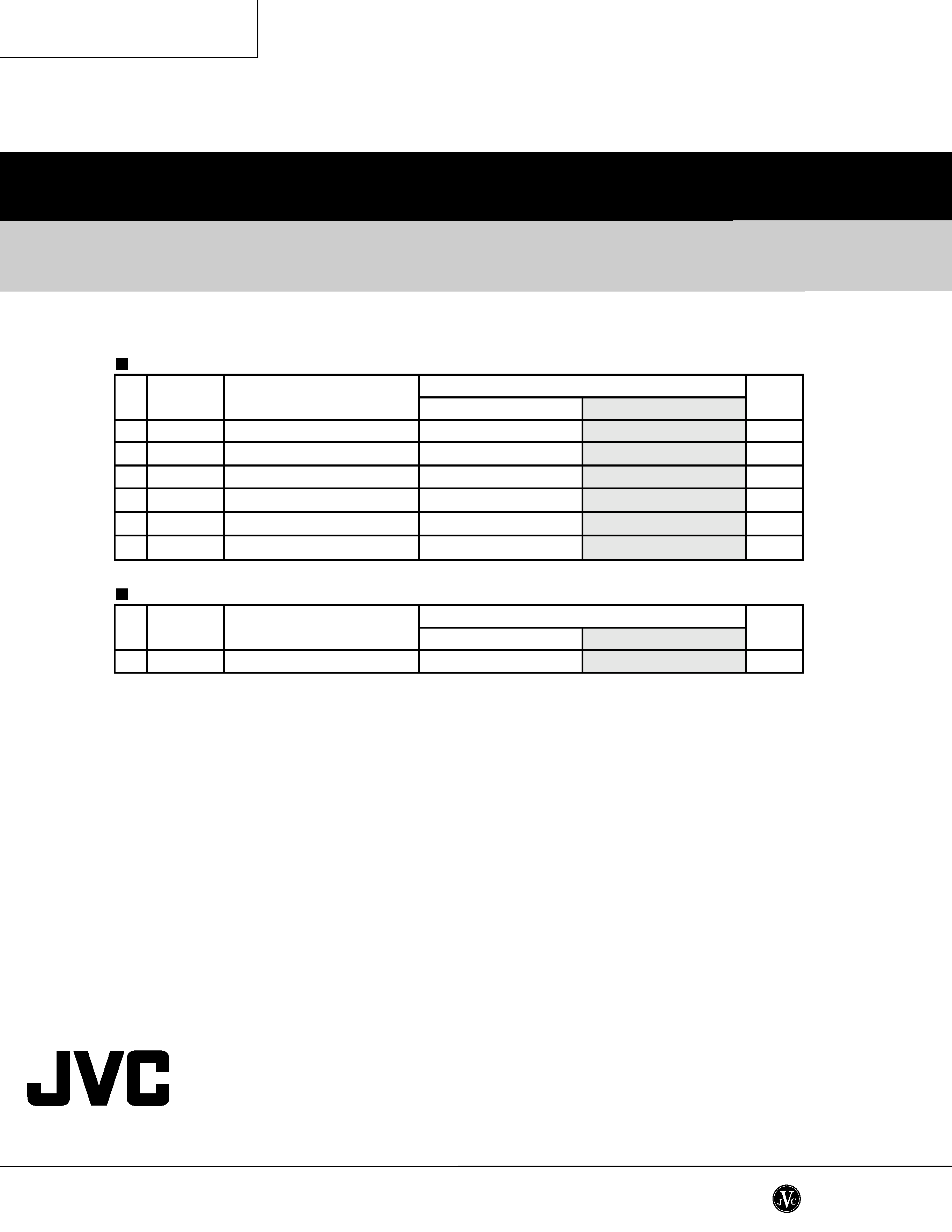
R421
R422
R423
MG RESISTOR
MG RESISTOR
MG RESISTOR
NRSA63J-0R0X
NRSA63J-0R0X
NRSA63J-0R0X
XV-S42SL ver.E
XV-S42SL ver.EE
A
Item
Parts name
Parts number
Electrical parts list (DVD servo control board)
P3-16 Block No.02
For XV-S42SL ver.EE
Printed in Japan
200107
No.A0006B
XV-S42SL/XV-S49BK
VICTOR COMPANY OF JAPAN, LIMITED
PERSONAL & MOBILE NETWORK BUSINESS UNIT
1644, Shimotsuruma, Yamato, Kanagawa 242-8514, Japan
1
4
6
10
25
40
FRONT PANEL
WINDOW SCREEN
PUSH BUTTON
PUSH BUTTON
FITTING
REAR PANEL
LE10251-026A
LE20535-006A
LE20537-001A
LE20538-001A
LE20536-001A
LE20542-024A
LE10251-036A
LE20535-016A
LE20537-006A
LE20538-005A
LE20536-008A
LE20542-072A
XV-S40BK ver.E
XV-S49BK ver.E
1
1
1
1
1
1
A
Item
Parts name
Parts number
Q'ty
Parts list (General assembly)
P3-3~4 Block No.M1MM
P2
PACKING CASE
LE30945-005A
GN10007-001A
XV-S40BK ver.E
XV-S49BK ver.E
1
A
Item
Parts name
Parts number
Q'ty
Packing parts list
P3-18 Block No.M4MM
For XV-S49BK ver.E
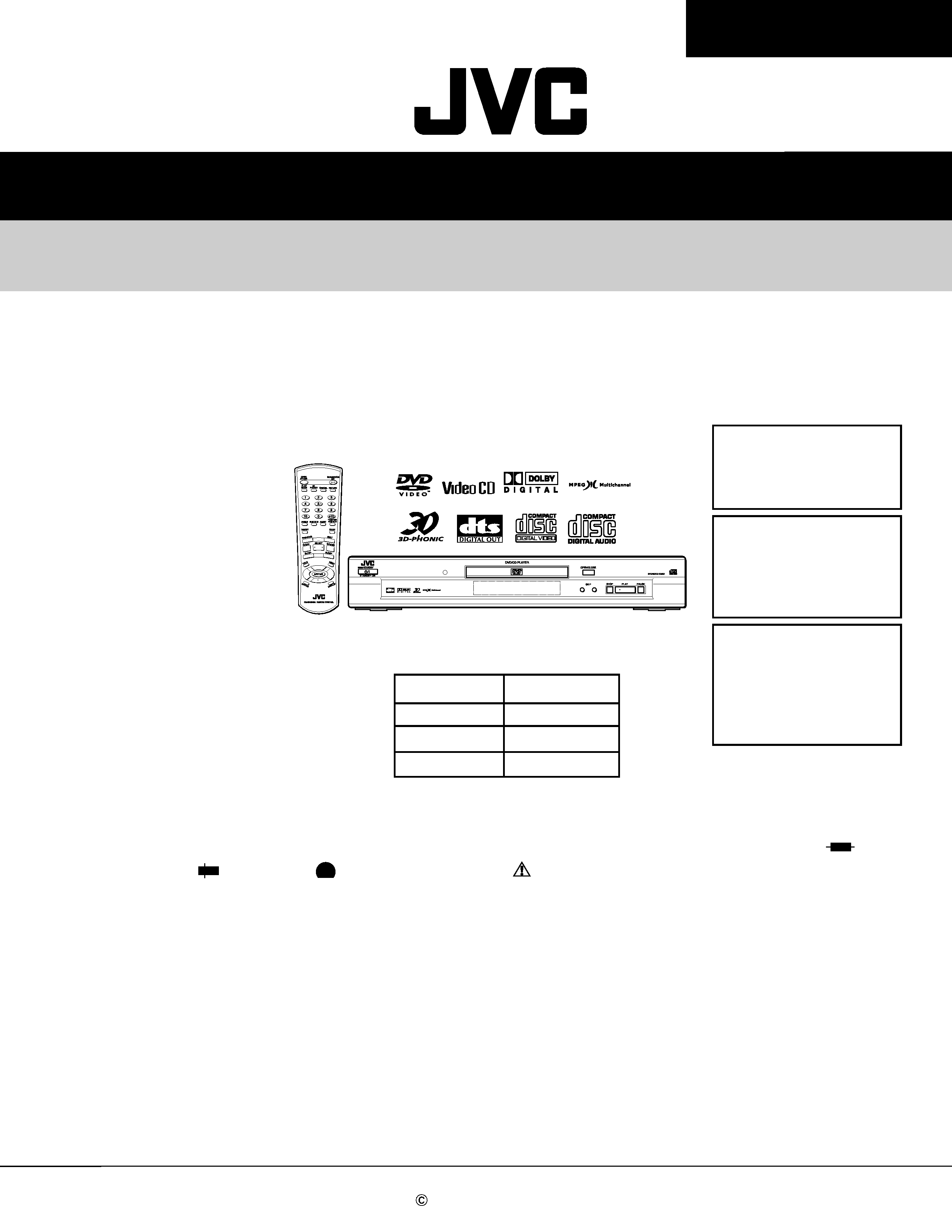
SERVICE MANUAL
DVD VIDEO PLAYER
No.A0006
Apr. 2001
COPYRIGHT
2001 VICTOR COMPANY OF JAPAN, LTD.
XV-S40BK / XV-S42SL
XV-E100SL
XV-S40BK/XV-S42SL
XV-E100SL
Area Suffix (XV-S42SL)
B ------------------------- U.K.
E --- Continental Europe
EN ---- Northern Europe
EV ------ Eastern Europe
Area Suffix(XV-E100SL)
B ------------------------- U.K.
E --- Continental Europe
EN ---- Northern Europe
EV ------ Eastern Europe
EE -- Russian Federation
B ------------------------- U.K.
E --- Continental Europe
EN ---- Northern Europe
Area Suffix (XV-S40BK)
This service manual is printed on 100% recycled paper.
Contents
Safety precautions ------------------------ 1-2
Preventing static electricity ------------- 1-3
Precautions for service ------------------ 1-4
Important for laser products ----------- 1-5
Disassembly method -------------------- 1-6
Adjustment method ---------------------- 1-15
Description of major ICs ---------------- 1-21
Model
XV-S40BK
XV-S42SL
XV-E100SL
Body color
Black
Silver
Silver
Each difference point
In regard with component parts appearing on the silk-screen printed side (parts side) of
the PWB diagrams, the parts that are printed over with black such as the resistor (
),
diode (
) and ICP (
) or identified by the "
" mark nearby are critical for safety.
When replacing them, be sure to use the parts of the same type and rating as specified
by the manufacturer. (Except the JC version)
XV-S40BK/XV-S42SL/XV-E100SL
1-2
1. This design of this product contains special hardware and many circuits and components specially
for safety purposes.
For continued protection, no changes should be made to the original design
unless authorized in writing by the manufacturer.
Replacement parts must be identical to those
used in the original circuits.
Services should be performed by qualified personnel only.
2. Alterations of the design or circuitry of the product should not be made.
Any design alterations of
the product should not be made.
Any design alterations or additions will
void the
warranty
and will further relieve the manufacture of responsibility for personal injury or property damage
resulting therefrom.
3. Many electrical and mechanical parts in the products have special safety-related characteristics.
These characteristics are often not evident from visual inspection nor can the protection afforded
by them necessarily be obtained by using replacement components rated for higher voltage,
wattage, etc.
Replacement parts which have these special safety characteristics are identified in
the Parts List of Service Manual.
Electrical components having such features are identified by
shading on the schematics and by (
) on the Parts List in the Service Manual.
The use of a
substitute replacement which does not have the same safety characteristics as the recommended
replacement parts shown in the Parts List of Service Manual may create shock, fire, or other
hazards.
4. The leads in the products are routed and dressed with ties, clamps, tubings, barriers and the
like to be separated from live parts, high temperature parts, moving parts and/or sharp edges
for the prevention of electric shock and fire hazard.
When service is required, the original lead
routing and dress should be observed, and it should be confirmed that they have been returned
to normal, after reassembling.
5. Leakage current check (Electrical shock hazard testing)
After reassembling the product, always perform an isolation check on the exposed metal parts of
the product (antenna terminals, knobs, metal cabinet, screw heads, headphone jack, control
shafts, etc.) to be sure the product is safe to operate without danger of electrical shock.
Do not use a line isolation transformer during this check.
Plug the AC line cord directly into the AC outlet.
Using a "Leakage Current Tester", measure
the leakage
current from each exposed metal parts of the cabinet , particularly any exposed
metal part having a return path to the chassis, to a known good earth ground. Any leakage
current must not exceed 0.5mA AC (r.m.s.)
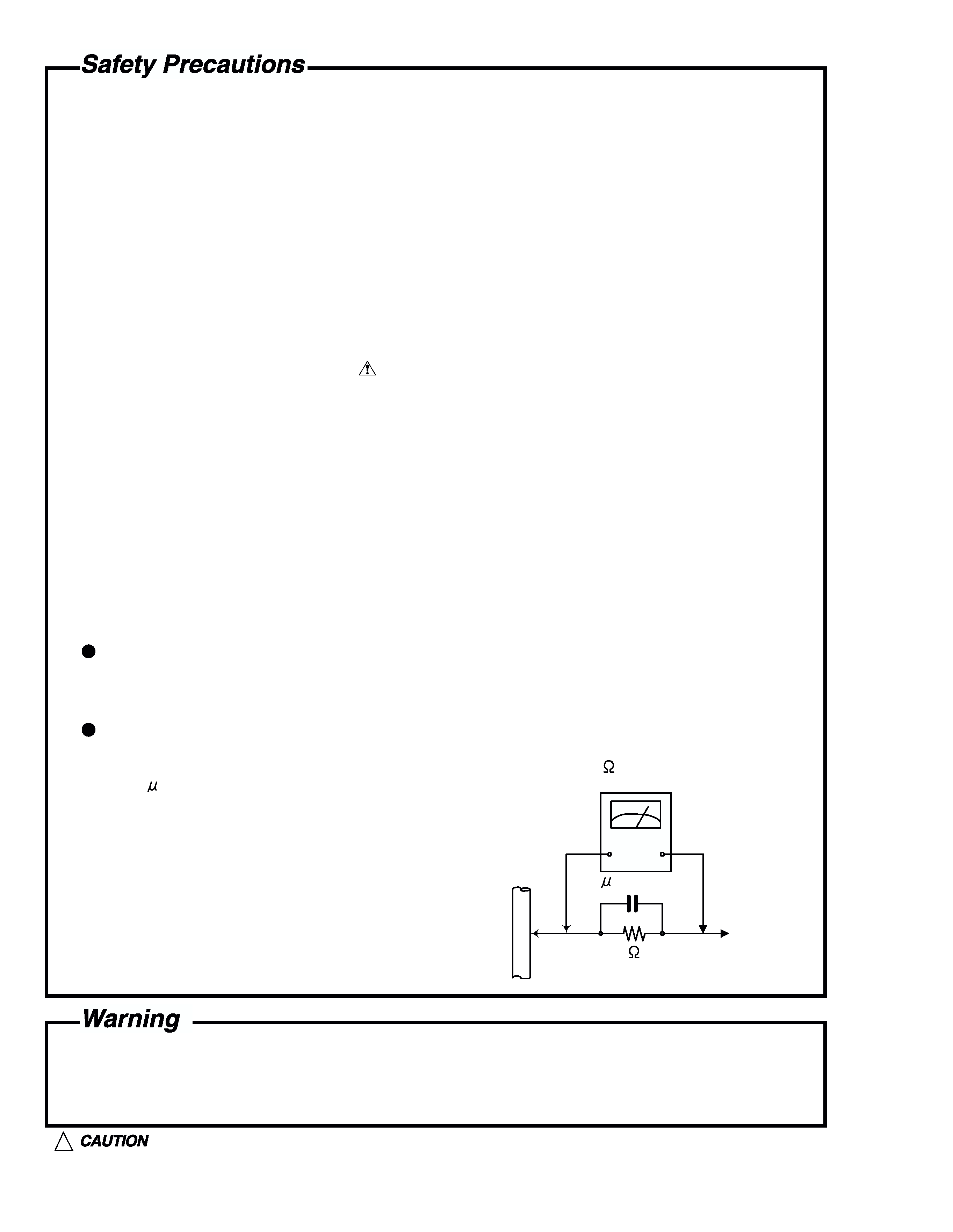
Alternate check method
Plug the AC line cord directly into the AC outlet.
Use an AC voltmeter having, 1,000 ohms
per volt or more sensitivity in the following manner. Connect a 1,500
10W resistor paralleled by
a 0.15 F AC-type capacitor between an exposed
metal part and a known good earth ground.
Measure the AC voltage across the resistor with the
AC voltmeter.
Move the
resistor
connection
to each exposed
metal part, particularly any exposed metal part
having a return path to the chassis, and measure
the AC voltage across the resistor. Now, reverse
the plug in the AC outlet and repeat each
measurement. voltage measured Any must
not
exceed 0.75 V AC (r.m.s.). This corresponds to 0.5
1. This equipment has been designed and manufactured to meet international safety standards.
2. It is the legal responsibility of the repairer to ensure that these safety standards are maintained.
3. Repairs must be made in accordance with the relevant safety standards.
4. It is essential that safety critical components are replaced by approved parts.
5. If mains voltage selector is provided, check setting for local voltage.
Good earth ground
Place this
probe on
each exposed
metal part.
AC VOLTMETER
(Having 1000
ohms/volts,
or more sensitivity)
1500
10W
0.15 F AC TYPE
!
Burrs formed during molding may be left over on some parts of the chassis. Therefore,
pay attention to such burrs in the case of preforming repair of this system.
XV-S40BK/XV-S42SL/XV-E100SL
1-3
Preventing static electricity
Electrostatic discharge (ESD), which occurs when static electricity stored in the body, fabric, etc. is discharged,
can destroy the laser diode in the traverse unit (optical pickup). Take care to prevent this when performing repairs.
1.1. Grounding to prevent damage by static electricity
Static electricity in the work area can destroy the optical pickup (laser diode) in devices such as DVD players.
Be careful to use proper grounding in the area where repairs are being performed.
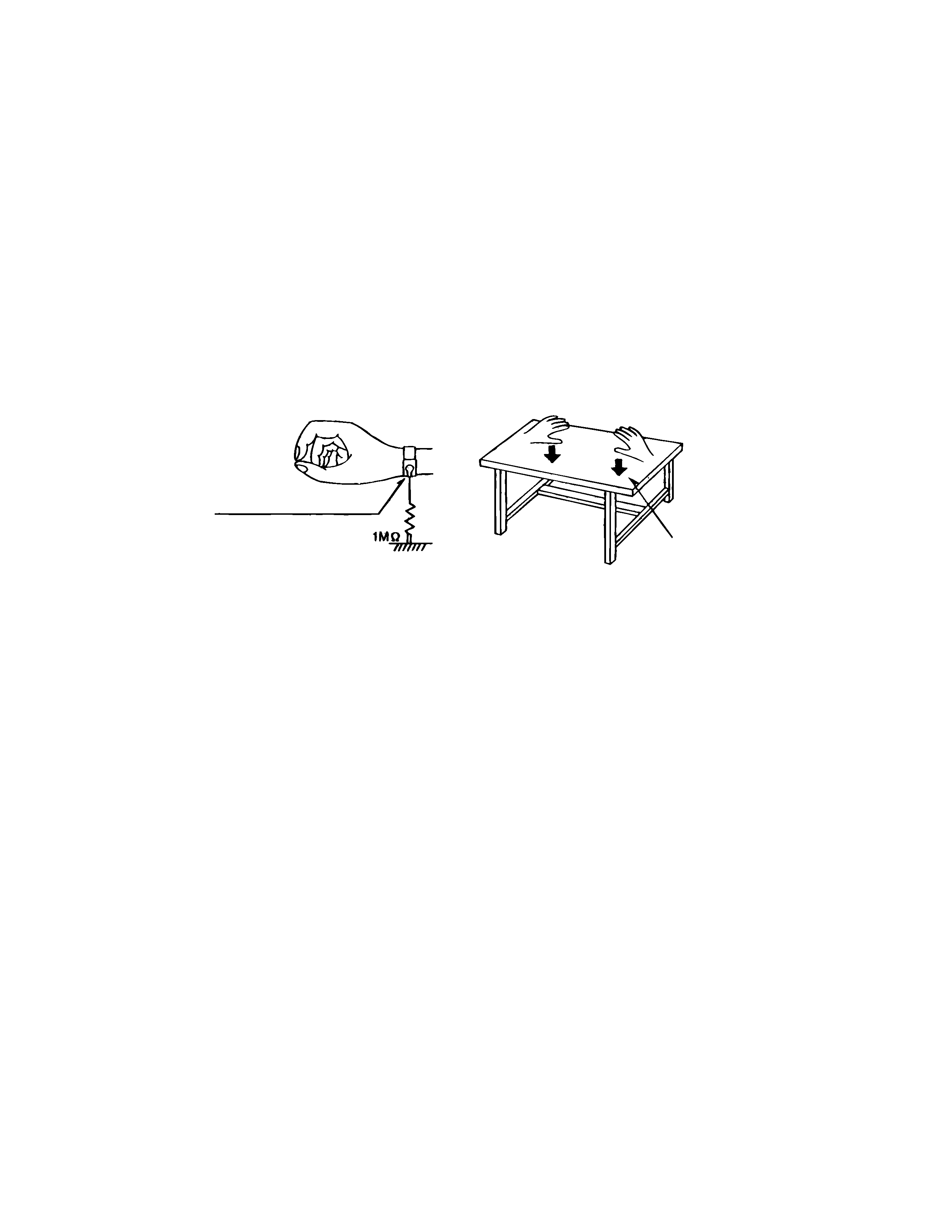
1.1.1. Ground the workbench
1. Ground the workbench by laying conductive material (such as a conductive sheet) or an iron plate over
it before placing the traverse unit (optical pickup) on it.
1.1.2. Ground yourself
1. Use an anti-static wrist strap to release any static electricity built up in your body.
1.1.3. Handling the optical pickup
1. In order to maintain quality during transport and before installation, both sides of the laser diode on the
replacement optical pickup are shorted. After replacement, return the shorted parts to their original condition.
(Refer to the text.)
2. Do not use a tester to check the condition of the laser diode in the optical pickup. The tester's internal power
source can easily destroy the laser diode.
1.2. Handling the traverse unit (optical pickup)
1. Do not subject the traverse unit (optical pickup) to strong shocks, as it is a sensitive, complex unit.
2. For specific details, refer to the replacement procedure in the text. Be careful not to take too long a time
when attaching it to the connector.
3. Handle the flexible cable carefully as it may break when subjected to strong force.
4. It is not possible to adjust the semi-fixed resistor that adjusts the laser power. Do not turn it
Conductive material
(conductive sheet) or iron plate
(caption)
Anti-static wrist strap