SERVICE MANUAL
COPYRIGHT © 2003 VICTOR COMPANY OF JAPAN, LIMITED.
No.XA003
2003/5
DVD VIDEO PLAYER
XA003
2003
5
XV-N40BK[MK2],
XV-N44SL[MK2],
XV-N4SL[MK2]
TABLE OF CONTENTS
1
Important Safety Precautions . . . . . . . . . . . . . . . . . . . . . . . . . . . . . . . . . . . . . . . . . . . . . . . . . . . . . . . . . . . 1-4
2
Disassembly method . . . . . . . . . . . . . . . . . . . . . . . . . . . . . . . . . . . . . . . . . . . . . . . . . . . . . . . . . . . . . . . . . . 1-8
3
Adjustment. . . . . . . . . . . . . . . . . . . . . . . . . . . . . . . . . . . . . . . . . . . . . . . . . . . . . . . . . . . . . . . . . . . . . . . . . . 1-15
4
Description of major ICs. . . . . . . . . . . . . . . . . . . . . . . . . . . . . . . . . . . . . . . . . . . . . . . . . . . . . . . . . . . . . . . 1-24
Area Suffix
(XV-N40BK,XV-N44SL)
J -------------------------- U.S.A.
C --------------------- Canada
Area Suffix (XV-N4SL)
C --------------------- Canada
2
5
8
1
4
7
3
6
9
0
10
+10
CANCEL
TITLE/
GROUP
RETURN
VFP
PROGRESSIVE
SCAN
REPEAT
ZOOM
DIMMER
AUDIO
3D
PHONIC
SUB TITLE
ANGLE
OPEN/
CLOSE
DISPLAY
NEXT
PREVIOUS
SELECT
CLEAR
SLOW-
SLOW+
TO
P
ME
NU
ME
NU
ON
SC
RE
EN
CH
OIC
E
ENTER
STANDBY/ON
VIDEO
This service manual is a service manual of the model which
changes a part of specification of the above-mentioned model
which has already been put on the market.
Please refer to the following page for details.
This illustration is XV-N40BK for U.S.A
1-2 (No.XA003)
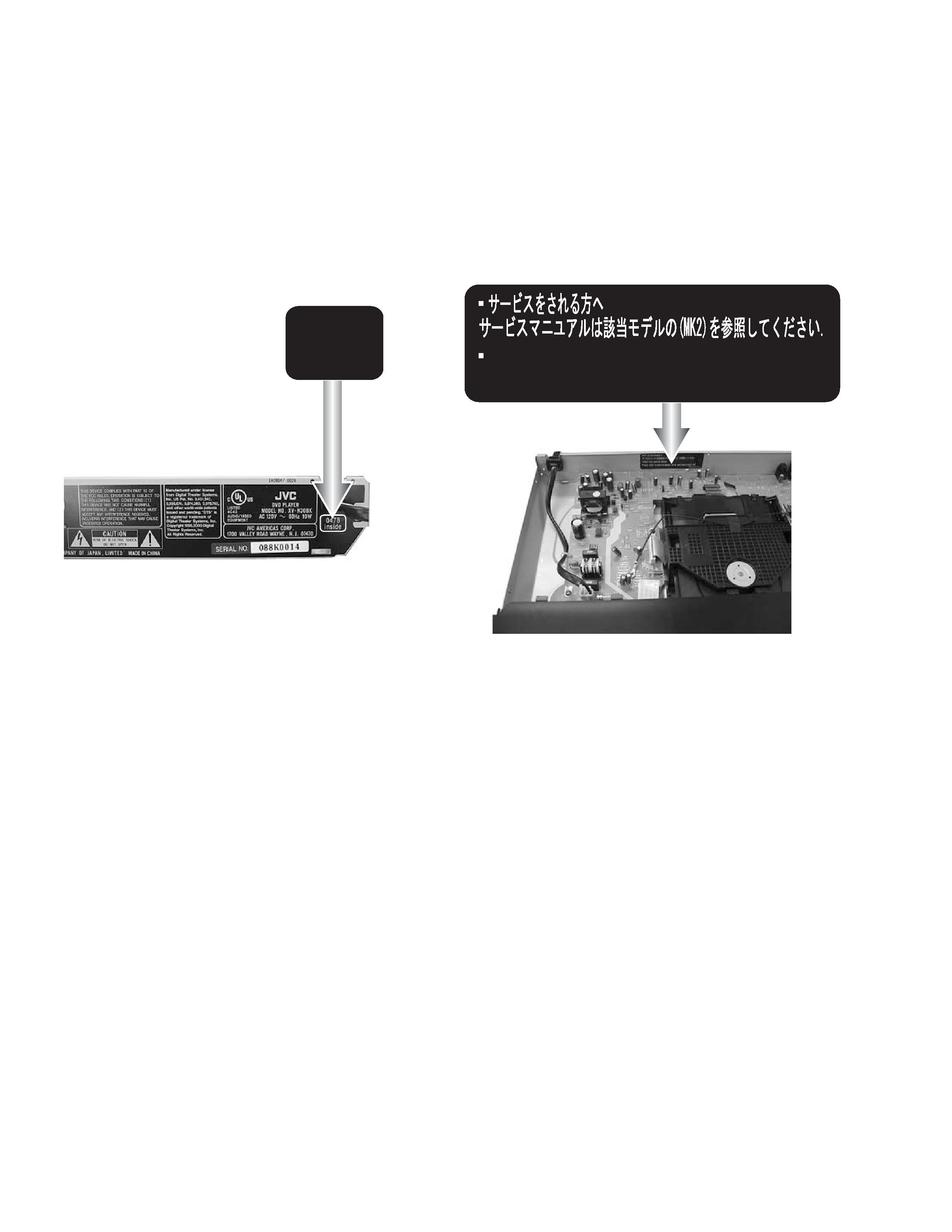
For this service manual
This service manual is a service manual of the model which changes a part of specification of the above-mentioned model
which has already been put on the market.
<When the label in figure is pasted in the main body>
The specification is different from what the label of the same model does not paste because of the specification improvement,
and refer to this service manual, please. Please already refer to the issued service manual when the label is not pasted.
* Please refer to this service manual for the model to which this label is pasted.
* Please refer to the service manual which has already been issued for the
model to which this label is not pasted.
(one that there is no description named [MK2] in cover of service manual. )
0478
inside
Used only service dealer
Please refer to service manual of an applicable model [MK2]
GN30080-001A
The surface of a rear panel
or
(No.XA003)1-3
SPECIFICATION
General
Other
Video outputs
Audio outputs
Audio characteristics
· Specifications and appearance are subject to change without prior notice.
· Manufactured under license from Dolby Laboratories. "Dolby" and the double-D symbol are trademarkes of Dolby Laboratories.
· Manufactured under license from Digital Theater Systems, Inc. "DTS" and "DTS Digital Surround" are registered trademarks of Dig-
ital Theater Systems, Inc.
Digital output signal chart
Readable discs
DVD VIDEO, DVD-R (Video format), DVDRW (Video format), +RW (Video format), SVCD, Video CD,
Audio CD (CD-DA), MP3 format, JPEG, CD-R/RW (CD-DA, SVCD, Video CD, MP3 format, JPEG)
Video format
NTSC, 480i (Interlaced scan)/480p (Progressive scan) selectable
Power requirements
AC 120 V, 60 Hz
Power consumption
10 W (POWER ON) 0.7 W (STANDBY mode)
Mass
2.1 kg (4.7 lbs)
Dimensions (W x H x D)
435mm x 53mm x 248.4mm (17-3/16 inch x 2-1/8 inc x 9-13/16 inch)
COMPONENT (pin jacks)
Y Output: 1.0 Vp-p (75
)
Pb/Pr Output: 0.7Vp-p (75
)
VIDEO OUT (pin jack)
1.0 Vp-p (75
)
S-VIDEO OUT (S jack)
Y Output: 1.0 Vp-p (75
)
C Output: 286 mVp-p (75
)
Horizontal resolution
500 lines or more
ANALOG OUT (pin jack)
2.0 Vrms (10 k
)
DIGITAL OUT (COAXIAL) 0.5 Vp-p (75
termination)
DIGITAL OUT (OPTICAL) -21 dBm to -15 dBm (peak)
Frequency response
CD (sampling frequency 44.1 kHz):2 Hz to 20 kHz
DVD (sampling frequency 48 kHz):2 Hz to 22 kHz
(4 Hz to 20 kHz for DTS and Dolby Digital bitstream signals)
DVD (sampling frequency 96 kHz):2 Hz to 44 kHz
Dynamic range
16 bit: More than 98 dB
20 bit: More than 100 dB
24 bit: More than 100 dB
Wow and flutter
Unmeasurable (less than + 0.002%)
Total harmonic distortion
less than 0.006%
Disc type
Output
PCM ONLY
DOLBY DIGITAL/PCM
STREAM/PCM
DVD with 48/44.1 kHz,
16/20/24 bit linear PCM
48/44.1 kHz, 16 bit, stereo linear PCM
DVD with 96 kHz,
16/22/24 bit linear PCM
48kHz, 16 bit, stereo linear PCM (Down sampling)
DVD with DTS
No output
DTS bitstream
DVD with Dolby Digital
48 kHz, 16 bit, stereo linear PCM
Dolby Digital bitstream
DVD with MPEG
Multichannel
48 kHz, 16 bit, stereo linear PCM
MPEG bitstream
SVCD/Video CD/Audio CD
44.1 kHz, 16 bit, stereo linear PCM
Audio CD with DTS
No output
DTS bitstream
CD-R/RW with MP3
Linear PCM
1-4 (No.XA003)
SECTION 1
Important Safety Precautions
1.1
Safety Precautions
(1) This design of this product contains special hardware and
many circuits and components specially for safety purpos-
es. For continued protection, no changes should be made
to the original design unless authorized in writing by the
manufacturer. Replacement parts must be identical to
those used in the original circuits. Services should be per-
formed by qualified personnel only.
(2) Alterations of the design or circuitry of the product should
not be made. Any design alterations of the product should
not be made. Any design alterations or additions will void
the manufacturers warranty and will further relieve the
manufacture of responsibility for personal injury or property
damage resulting therefrom.
(3) Many electrical and mechanical parts in the products have
special safety-related characteristics. These characteris-
tics are often not evident from visual inspection nor can the
protection afforded by them necessarily be obtained by us-
ing replacement components rated for higher voltage, watt-
age, etc. Replacement parts which have these special
safety characteristics are identified in the Parts List of Ser-
vice Manual. Electrical components having such features
are identified by shading on the schematics and by (
) on
the Parts List in the Service Manual. The use of a substitute
replacement which does not have the same safety charac-
teristics as the recommended replacement parts shown in
the Parts List of Service Manual may create shock, fire, or
other hazards.
(4) The leads in the products are routed and dressed with ties,
clamps, tubings, barriers and the like to be separated from
live parts, high temperature parts, moving parts and/or
sharp edges for the prevention of electric shock and fire
hazard. When service is required, the original lead routing
and dress should be observed, and it should be confirmed
that they have been returned to normal, after reassem-
bling.
(5) Leakage shock hazard testing
After reassembling the product, always perform an isola-
tion check on the exposed metal parts of the product (an-
tenna terminals, knobs, metal cabinet, screw heads,
headphone jack, control shafts, etc.) to be sure the product
is safe to operate without danger of electrical shock.Do not
use a line isolation transformer during this check.
· Plug the AC line cord directly into the AC outlet. Using a
"Leakage Current Tester", measure the leakage current
from each exposed metal parts of the cabinet, particular-
ly any exposed metal part having a return path to the
chassis, to a known good earth ground. Any leakage cur-
rent must not exceed 0.5mA AC (r.m.s.).
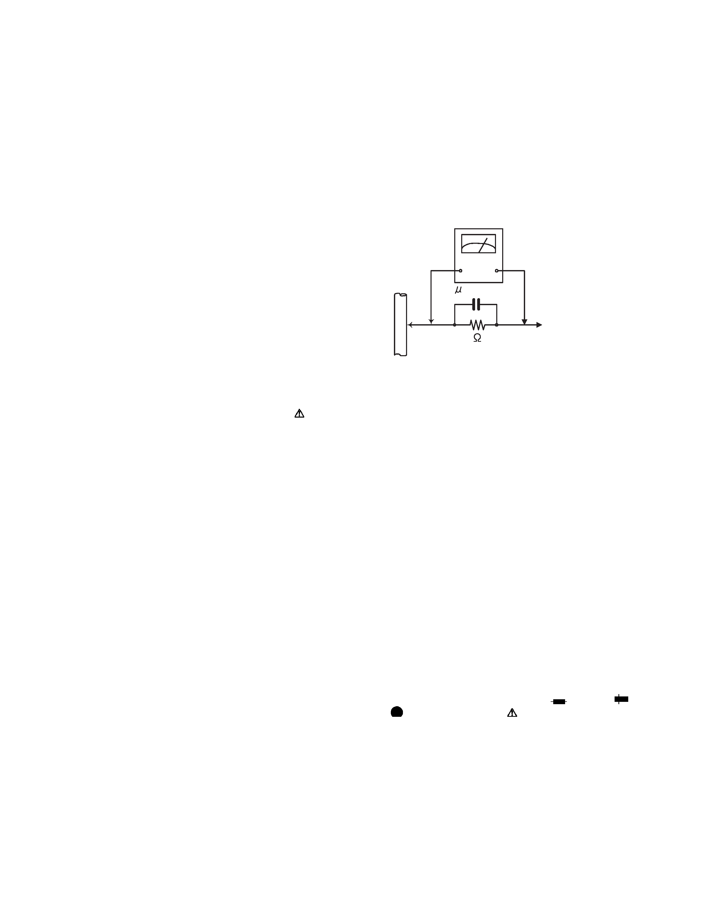
· Alternate check method
Plug the AC line cord directly into the AC outlet. Use an
AC voltmeter having, 1,000
per volt or more sensitivity
in the following manner. Connect a 1,500
10W resistor
paralleled by a 0.15
µF AC-type capacitor between an ex-
posed metal part and a known good earth ground.
Measure the AC voltage across the resistor with the AC
voltmeter.
Move the resistor connection to each exposed metal
part, particularly any exposed metal part having a return
path to the chassis, and measure the AC voltage across
the resistor. Now, reverse the plug in the AC outlet and
repeat each measurement. Voltage measured any must
not exceed 0.75 V AC (r.m.s.). This corresponds to 0.5
µ
mA AC (r.m.s.).
1.2
Warning
(1) This equipment has been designed and manufactured to
meet international safety standards.
(2) It is the legal responsibility of the repairer to ensure that
these safety standards are maintained.
(3) Repairs must be made in accordance with the relevant
safety standards.
(4) It is essential that safety critical components are replaced
by approved parts.
(5) If mains voltage selector is provided, check setting for local
voltage.
1.3
Caution
Burrs formed during molding may be left over on some parts
of the chassis.
Therefore, pay attention to such burrs in the case of pre-
forming repair of this system.
1.4
Critical parts for safety
In regard with component parts appearing on the silk-screen
printed side (parts side) of the PWB diagrams, the parts that are
printed over with black such as the resistor (
), diode (
)
and ICP (
) or identified by the "
" mark nearby are critical
for safety. When replacing them, be sure to use the parts of the
same type and rating as specified by the manufacturer.
(This regulation dose not Except the J and C version)
Good earth ground
Place this
probe on
each exposed
metal part.
AC VOLTMETER
(Having 1000
ohms/volts,
or more sensitivity)
1500
10W
0.15 F AC TYPE
(No.XA003)1-5
1.5
Preventing static electricity
Electrostatic discharge (ESD), which occurs when static electricity stored in the body, fabric, etc. is discharged, can destroy the laser
diode in the traverse unit (optical pickup). Take care to prevent this when performing repairs.
1.5.1
Grounding to prevent damage by static electricity
Static electricity in the work area can destroy the optical pickup (laser diode) in devices such as DVD players.
Be careful to use proper grounding in the area where repairs are being performed.
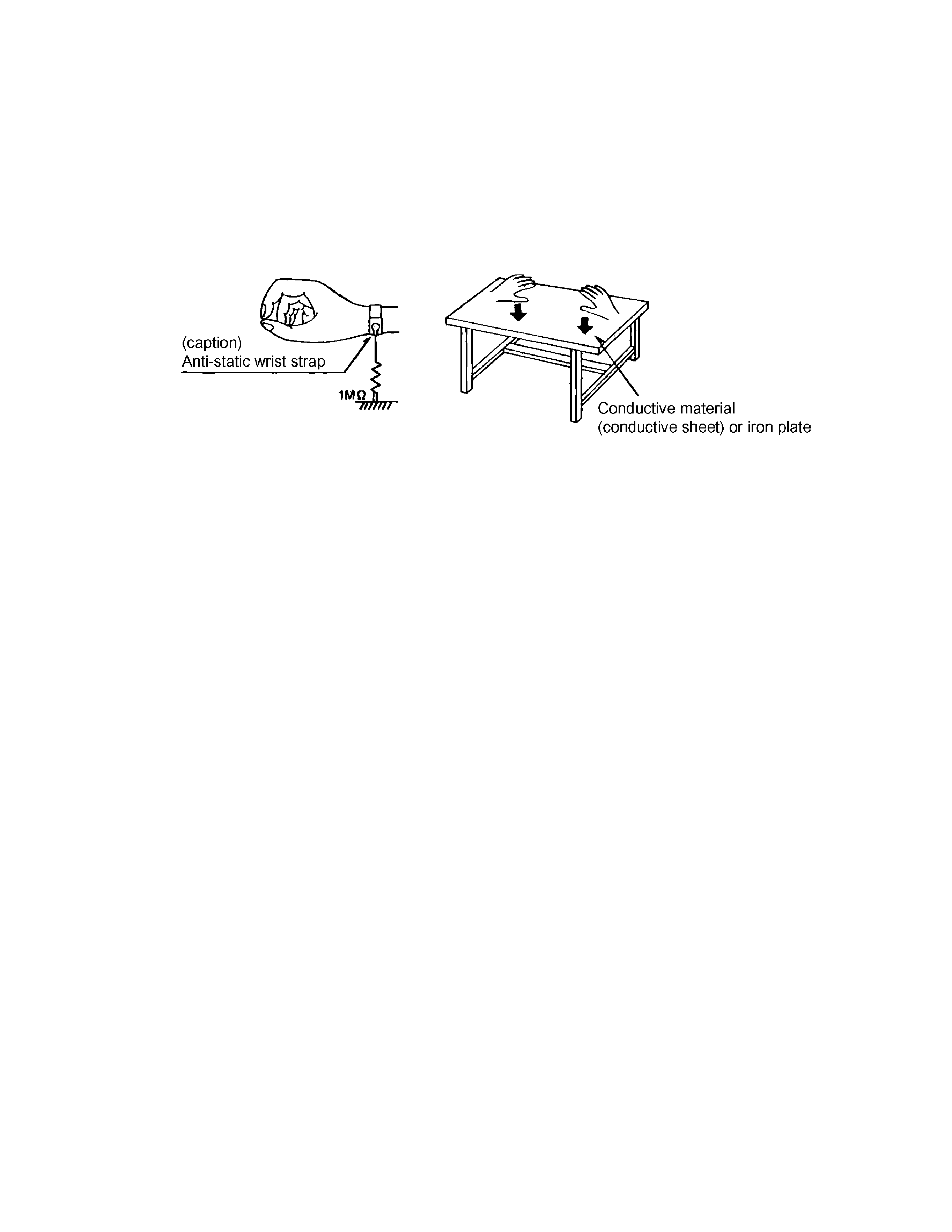
(1) Ground the workbench
Ground the workbench by laying conductive material (such as a conductive sheet) or an iron plate over it before placing the
traverse unit (optical pickup) on it.
(2) Ground yourself
Use an anti-static wrist strap to release any static electricity built up in your body.
(3) Handling the optical pickup
· In order to maintain quality during transport and before installation, both sides of the laser diode on the replacement optical
pickup are shorted. After replacement, return the shorted parts to their original condition.
(Refer to the text.)
· Do not use a tester to check the condition of the laser diode in the optical pickup. The tester's internal power source can easily
destroy the laser diode.
1.6
Handling the traverse unit (optical pickup)
(1) Do not subject the traverse unit (optical pickup) to strong shocks, as it is a sensitive, complex unit.
(2) Cut off the shorted part of the flexible cable using nippers, etc. after replacing the optical pickup. For specific details, refer to the
replacement procedure in the text. Remove the anti-static pin when replacing the traverse unit. Be careful not to take too long
a time when attaching it to the connector.
(3) Handle the flexible cable carefully as it may break when subjected to strong force.
(4) I t is not possible to adjust the semi-fixed resistor that adjusts the laser power. Do not turn it.
1.7
Precautions of the safe use of battery (Only XV-N4SL)
· Store the battery in a place where children cannot reach.If a child accidentally swallows the battery, consult a doctorimmediately.
· Do not recharge, short, disassemble or heat the battery or dispose of it in a fire.
Doing any of these things may cause the battery to give off heat, crack, or start a fire.
· Do not leave the battery with other metallic materials.Doing this may cause the battery to give off heat, crack, or start a fire.
· When throwing away or saving the battery, wrap it in tape and insulate; otherwise, the battery may start to give off heat, crack, or
start a fire.
· Do not poke the battery with tweezers or similar tools.Doing this may cause the battery to give off heat, crack, or start a fire.
· Dispose of batteries in the proper manner, according to federal, state, and local regulations.