SERVICE MANUAL
COPYRIGHT © 2003 VICTOR COMPANY OF JAPAN, LIMITED.
No.A0039
2003/03
XV-N30BK,XV-N33SL
DVD VIDEO PLAYER
A0039
2003
03
XV-N30BK,XV-N33SL
TABLE OF CONTENTS
1
Important Safety Precautions . . . . . . . . . . . . . . . . . . . . . . . . . . . . . . . . . . . . . . . . . . . . . . . . . . . . . . . . . . . 1-3
2
Disassembly method . . . . . . . . . . . . . . . . . . . . . . . . . . . . . . . . . . . . . . . . . . . . . . . . . . . . . . . . . . . . . . . . . . 1-8
3
Adjustment. . . . . . . . . . . . . . . . . . . . . . . . . . . . . . . . . . . . . . . . . . . . . . . . . . . . . . . . . . . . . . . . . . . . . . . . . . 1-15
4
Description of major ICs. . . . . . . . . . . . . . . . . . . . . . . . . . . . . . . . . . . . . . . . . . . . . . . . . . . . . . . . . . . . . . . 1-24
2
13
5
8
4
7
6
9
0
10
+10
DISPLAY
3D PHONIC
ANGLE
TOP MENU
MENU
CHOICE
PREVIOUS
SELECT
CLEAR
NEXT
VFP
ON SCREEN
ENTER
SUB TITLE AUDIO
ZOOM
TITLE/
GROUP
RETURN
CANCEL
STANDBY/ON
SLOW
Area Suffix (XV-N30BK)
J -------------------------- U.S.A.
C --------------------- Canada
UJ ------------ U.S.A Militaly
B -------------------------- U.K.
E ------ Continental Europe
EN ------- Northern Europe
EV --------- Eastern Europe
EE ---- Russian Federation
Area Suffix (XV-N33SL)
J -------------------------- U.S.A.
C --------------------- Canada
UJ ------------ U.S.A Militaly
B -------------------------- U.K.
E ------ Continental Europe
EN ------- Northern Europe
EV --------- Eastern Europe
EE ---- Russian Federation
US ---------------- Singapore
UG - Turkey,South Africa,Egypt
UX ------------- Saudi Arabia
UP ---------------------- Korea
UF ---------------------- China
UB --------------- Hong Kong
A --------------------- Australia
UW ----- Brazil,Mexico,Peru
UY ----------------- Argentina
This illustration is XV-N30BK for U.S.A.
For only Europe
XV-N30BK,XV-N33SL
1-2 (No.A0039)
SPECIFICATION
(For U.S.A.)
General
Other
Video outputs
Audio outputs
Audio characteristics
· Specifications and appearance are subject to change without prior notice.
· Manufactured under license from Dolby Laboratories. "Dolby" and the double-D symbol are trademarkes of Dolby Laboratories.
· Manufactured under license from Digital Theater Systems, Inc. "DTS" and "DTS Digital Surround" are registered trademarks of Dig-
ital Theater Systems, Inc.
Readable discs
DVD VIDEO, DVD-R (Video format), DVD-RW (Video format), +RW (Video format), SVCD, Video CD,
Audio CD (CD-DA), MP3 format, CD-R/RW (CD-DA, SVCD, Video CD, MP3 format)
Video format
NTSC
Power requirements
AC 120 V, 60 Hz
Power consumption
10.4 W (POWER ON) 0.7 W (STANDBY mode)
Mass
2.1 kg (4.7 lbs)
Dimensions (W x H x D)
435mm x 53mm x 248.4mm (17-3/16 inch x 2-1/8 inc x 9-13/16 inch)
COMPONENT (pin jacks)
Y Output: 1.0 Vp-p (75 ohm)
Pb/Pr Output: 0.7Vp-p (75 ohm)
VIDEO OUT (pin jack)
1.0 Vp-p (75 ohm)
S-VIDEO OUT (S jack)
Y Output: 1.0 Vp-p (75 ohm)
C Output: 286 mVp-p (75 ohm)
Horizontal resolution
500 lines or more
ANALOG OUT (pin jack)
2.0 Vrms (10 kohm)
DIGITAL OUT (COAXIAL) 0.5 Vp-p (75 ohm termination)
DIGITAL OUT (OPTICAL) -21 dBm to -15 dBm (peak)
Frequency response
CD (sampling frequency 44.1 kHz):2 Hz to 20 kHz
DVD (sampling frequency 48 kHz):2 Hz to 22 kHz
(4 Hz to 20 kHz for DTS and Dolby Digital bitstream signals)
DVD (sampling frequency 96 kHz):2 Hz to 44 kHz
Dynamic range
16 bit: More than 98 dB
20 bit: More than 100 dB
24 bit: More than 100 dB
Wow and flutter
Unmeasurable (less than + 0.002%)
Total harmonic distortion
less than 0.006%
XV-N30BK,XV-N33SL
(No.A0039)1-3
SECTION 1
Important Safety Precautions
1.1 Safety Precautions
(1) This design of this product contains special hardware and
many circuits and components specially for safety purposes.
For continued protection, no changes should be made to the
original design unless authorized in writing by the man-
ufacturer. Replacement parts must be identical to those
used in the original circuits. Services should be per-
formed by qualified personnel only.
(2) Alterations of the design or circuitry of the product should
not be made. Any design alterations of the product should
not be made. Any design alterations or additions will void
the manufacturers warranty and will further relieve the
manufacture of responsibility for personal injury or property
damage resulting therefrom.
(3) Many electrical and mechanical parts in the products have
special safety-related characteristics. These characteris-
tics are often not evident from visual inspection nor can the
protection afforded by them necessarily be obtained by us-
ing replacement components rated for higher voltage, watt-
age, etc. Replacement parts which have these special safety
characteristics are identified in the Parts List of Service Manu-
al. Electrical components having such features are iden-
tified by shading on the schematics and by (
) on the
Parts List in the Service Manual. The use of a substitute re-
placement which does not have the same safety character-
istics as the recommended replacement parts shown in the
Parts List of Service Manual may create shock, fire, or oth-
er hazards.
(4) The leads in the products are routed and dressed with ties,
clamps, tubings, barriers and the like to be separated from
live parts, high temperature parts, moving parts and/or
sharp edges for the prevention of electric shock and fire
hazard. When service is required, the original lead routing
and dress should be observed, and it should be confirmed
that they have been returned to normal, after reassembling.
(5) Leakage shock hazard testing)
After reassembling the product, always perform an isolation
check on the exposed metal parts of the product (antenna
terminals, knobs, metal cabinet, screw heads, headphone
jack, control shafts, etc.) to be sure the product is safe to
operate without danger of electrical shock.
Do not use a line isolation transformer during this check.
· Plug the AC line cord directly into the AC outlet. Using a
"Leakage Current Tester", measure the leakage current
from each exposed metal parts of the cabinet, particular-
ly any exposed metal part having a return path to the
chassis, to a known good earth ground. Any leakage cur-
rent must not exceed 0.5mA AC (r.m.s.).
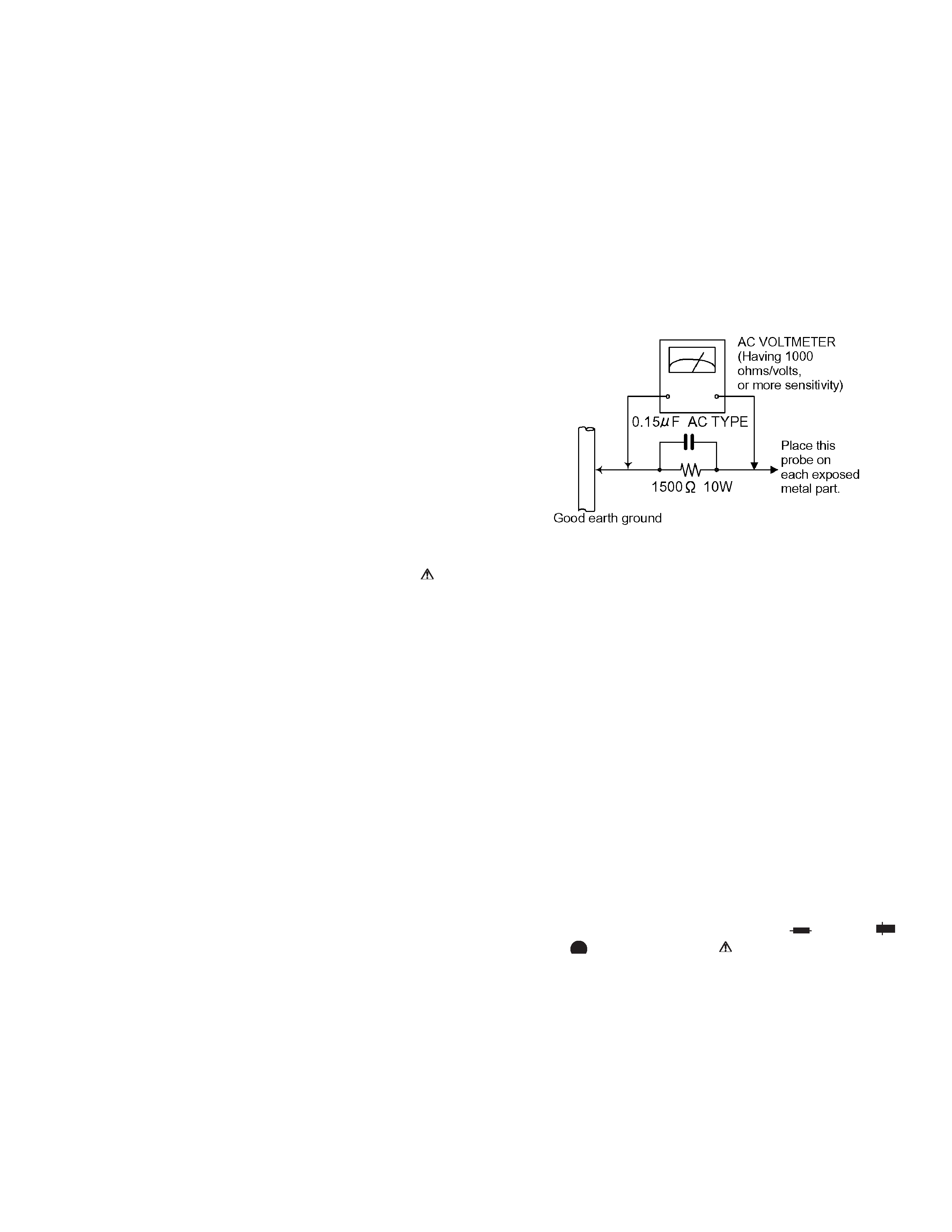
· Alternate check method
Plug the AC line cord directly into the AC outlet. Use an AC
voltmeter having, 1,000 ohms per volt or more sensitivity in
the following manner. Connect a 1,500 ohm 10W resistor
paralleled by a 0.15 µF AC-type capacitor between an
exposed metal part and a known good earth ground.
Measure the AC voltage across the resistor with the AC
voltmeter.
Move the resistor connection to each exposed metal part,
particularly any exposed metal part having a return path to
the chassis, and measure the AC voltage across the resistor.
Now, reverse the plug in the AC outlet and repeat each
measurement. Voltage measured any must not exceed 0.75
V AC (r.m.s.). This corresponds to 0.5 mA AC (r.m.s.).
1.2 Warning
(1) This equipment has been designed and manufactured to
meet international safety standards.
(2) It is the legal responsibility of the repairer to ensure that
these safety standards are maintained.
(3) Repairs must be made in accordance with the relevant
safety standards.
(4) It is essential that safety critical components are replaced
by approved parts.
(5) If mains voltage selector is provided, check setting for local
voltage.
1.3 Caution
Burrs formed during molding may be left over on some parts
of the chassis.
Therefore, pay attention to such burrs in the case of pre-
forming repair of this system.
1.4 Critical parts for safety
In regard with component parts appearing on the silk-screen
printed side (parts side) of the PWB diagrams, the parts that are
printed over with black such as the resistor (
), diode (
)
and ICP (
) or identified by the " " mark nearby are critical for
safety.
When replacing them, be sure to use the parts of the same type
and rating as specified by the manufacturer. (Except the JC version)
XV-N30BK,XV-N33SL
1-4 (No.A0039)
1.5 Preventing static electricity
Electrostatic discharge (ESD), which occurs when static electricity stored in the body, fabric, etc. is discharged,
can destroy the laser diode in the traverse unit (optical pickup). Take care to prevent this when performing repairs.
1.5.1
Grounding to prevent damage by static electricity
Static electricity in the work area can destroy the optical pickup (laser diode) in devices such as DVD players.
Be careful to use proper grounding in the area where repairs are being performed.
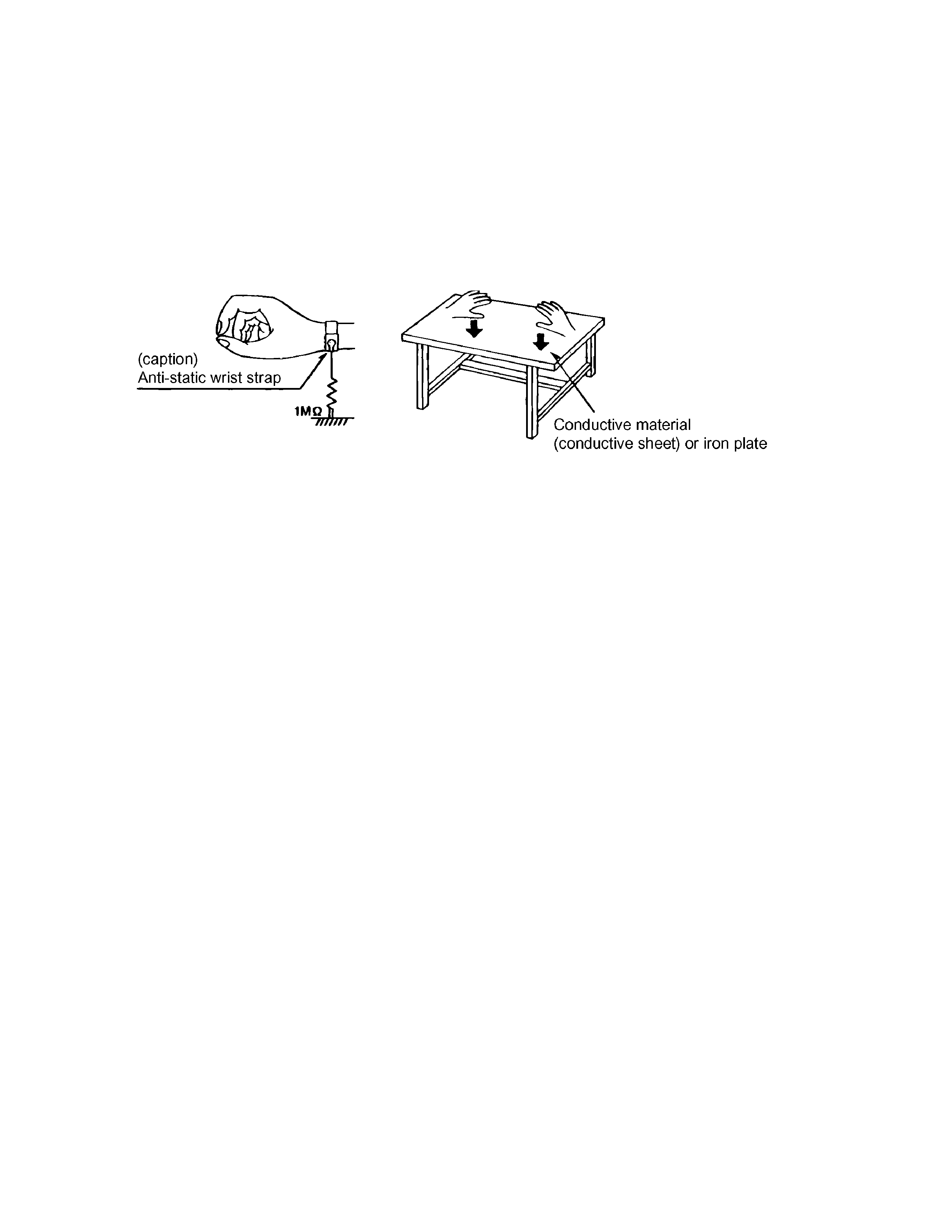
(1) Ground the workbench
Ground the workbench by laying conductive material (such as a conductive sheet) or an iron plate over it before placing the
traverse unit (optical pickup) on it.
(2) Ground yourself
Use an anti-static wrist strap to release any static electricity built up in your body.
(3) Handling the optical pickup
· In order to maintain quality during transport and before installation, both sides of the laser diode on the replacement optical
pickup are shorted. After replacement, return the shorted parts to their original condition.
(Refer to the text.)
· Do not use a tester to check the condition of the laser diode in the optical pickup. The tester's internal power source can easily
destroy the laser diode.
1.6 Handling the traverse unit (optical pickup)
(1) Do not subject the traverse unit (optical pickup) to strong shocks, as it is a sensitive, complex unit.
(2) Cut off the shorted part of the flexible cable using nippers, etc. after replacing the optical pickup. For specific details, refer to the
replacement procedure in the text. Remove the anti-static pin when replacing the traverse unit. Be careful not to take too long
a time when attaching it to the connector.
(3) Handle the flexible cable carefully as it may break when subjected to strong force.
(4) I t is not possible to adjust the semi-fixed resistor that adjusts the laser power. Do not turn it.
1.7 Precautions of the safe use of battery (Only XV-N30BK for U.S.A.)
· Store the battery in a place where children cannot reach.
If a child accidentally swallows the battery, consult a doctorimmediately.
· Do not recharge, short, disassemble or heat the battery or dispose of it in a fire.
Doing any of these things may cause the battery to give off heat, crack, or start a fire.
· Do not leave the battery with other metallic materials.
Doing this may cause the battery to give off heat, crack, or start a fire.
· When throwing away or saving the battery, wrap it in tape and insulate; otherwise, the battery may start to give off heat, crack, or
start a fire.
· Do not poke the battery with tweezers or similar tools.
Doing this may cause the battery to give off heat, crack, or start a fire.
· Dispose of batteries in the proper manner, according to federal, state, and local regulations.
XV-N30BK,XV-N33SL
(No.A0039)1-5
1.8 Importance admistering point on the safety
C701
C706
C902
C904
C905
C907
C908
C913
C914
C918
C950
C951
C953
C955
C957
B34
C959
B139
C965
C966
C967
B15
C973
C974
C975
B276
C977
B772
C988
B4
CN904
D901
CP951
D701
D953
CN901
D904
B873
B166
C906
EP951
FC901
FC902
IC901
IC952
J702
L709
L710
L901
L951
L952
L954
B116
L955
B532
C976
P704
P901
B304
PC901
Q953
B45
R901
R903
R906
R910
R912
R913
R953
R954
S901
T901
X701
S902
C952
B234
C970
B236
D956
B137
L956
L957
L959
B333
B533
B771
B32
B138
B852
B874
B872
B871
B140
B272
B332
B601
B141
B16
B331
B136
B403
B271
B38
B39
B36
B142
B143
B40
B133
B134
B132
B202
B231
B233
B105
B41
B201
B103
B101
B171
B44
D955
B303
B135
CN902
B273
B631
B37
L953
R966
R951
R915
C808
C802
B2
B237
Q951
B203
B102
C958
D957
D954
D952
D951
D903
D902
B347
EP952
C963
C964
B107
B205
EP953
R969
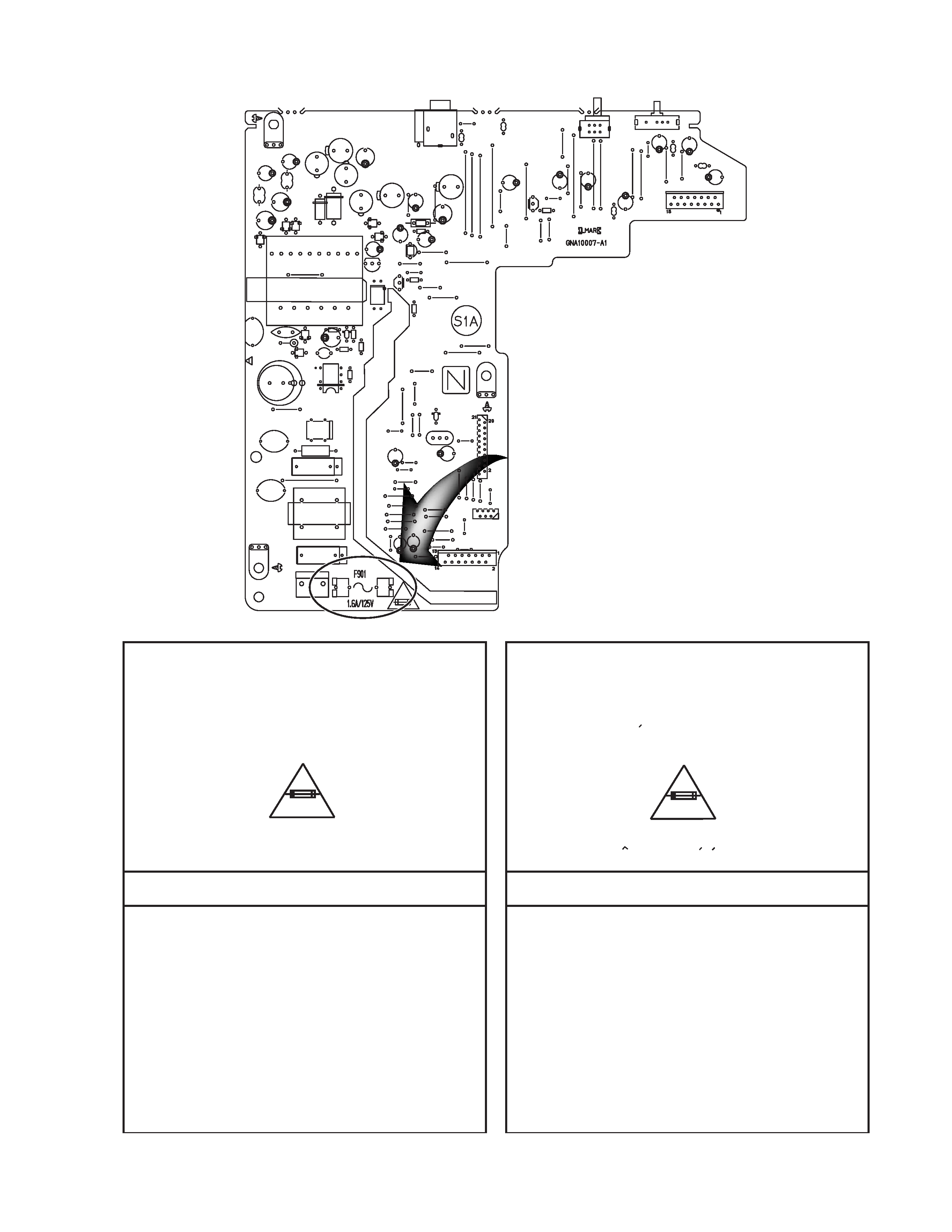
Full Fuse Replacement Marking
Graphic symbol mark
(This symbol means fast blow type fuse.)
should be read as follows ;
FUSE CAUTION
FOR CONTINUED PROTECTION AGAINST RISK
OF FIRE, REPLACE ONLY WITH SAME TYPE
AND RATING OF FUSES ;
F901 : 1.6 A / 125 V
F901 : 1.6 A / 125 V
Marquage Pour Le Remplacement
Complet De Fusible
PRECAUTIONS SUR LES FUSIBLES
POUR UNE PROTECTION CONTINUE CONTRE
DES RISQUES D'INCENDIE, REMPLACER
SEULEMENT PAR UN FUSIBLE DU MEME TYPE ;
Le symbole graphique (Ce symbole signifie
fusible de type a fusion rapide.)
doit etre interprete comme suit ;