SERVICE MANUAL
DVD VIDEO PLAYER
No.A0020
Nov. 2001
COPYRIGHT
2001 VICTOR COMPANY OF JAPAN, LTD.
XV-LTR1
XV-LTR1
Area Suffix
J --------- U.S.A.
This service manual is printed on 100% recycled paper.
Contents
Safety precautions ------------------------ 1-2
Preventing static electricity ------------- 1-3
Importance admistering
point on the safety ------------ 1-4
Precautions for service ----------------- 1-5
Disassembly method -------------------- 1-6
Adjustment method ---------------------- 1-15
Troubleshooting -------------------------- 1-19
Description of major ICs ---------------- 1-23
XV-LTR1
1-2
1. This design of this product contains special hardware and many circuits and components specially for safety
purposes. For continued protection, no changes should be made to the original design unless authorized in
writing by the manufacturer. Replacement parts must be identical to those used in the original circuits. Services
should be performed by qualified personnel only.
2. Alterations of the design or circuitry of the product should not be made. Any design alterations of the product
should not be made. Any design alterations or additions will void the manufacturers warranty and will further
relieve the manufacture of responsibility for personal injury or property damage resulting therefrom.
3. Many electrical and mechanical parts in the products have special safety-related characteristics. These
characteristics are often not evident from visual inspection nor can the protection afforded by them necessarily
be obtained by using replacement components rated for higher voltage, wattage, etc. Replacement parts which
have these special safety characteristics are identified in the Parts List of Service Manual. Electrical
components having such features are identified by shading on the schematics and by (
) on the Parts List in
the Service Manual. The use of a substitute replacement which does not have the same safety characteristics
as the recommended replacement parts shown in the Parts List of Service Manual may create shock, fire, or
other hazards.
4. The leads in the products are routed and dressed with ties, clamps, tubings, barriers and the like to be
separated from live parts, high temperature parts, moving parts and/or sharp edges for the prevention of
electric shock and fire hazard. When service is required, the original lead routing and dress should be
observed, and it should be confirmed that they have been returned to normal, after reassembling.
5. Leakage current check (Electrical shock hazard testing)
After reassembling the product, always perform an isolation check on the exposed metal parts of the product
(antenna terminals, knobs, metal cabinet, screw heads, headphone jack, control shafts, etc.) to be sure the
product is safe to operate without danger of electrical shock.
Do not use a line isolation transformer during this check.
Plug the AC line cord directly into the AC outlet. Using a "Leakage Current Tester", measure the leakage
current from each exposed metal parts of the cabinet, particularly any exposed metal part having a return
path to the chassis, to a known good earth ground. Any leakage current must not exceed 0.5mA AC (r.m.s.).
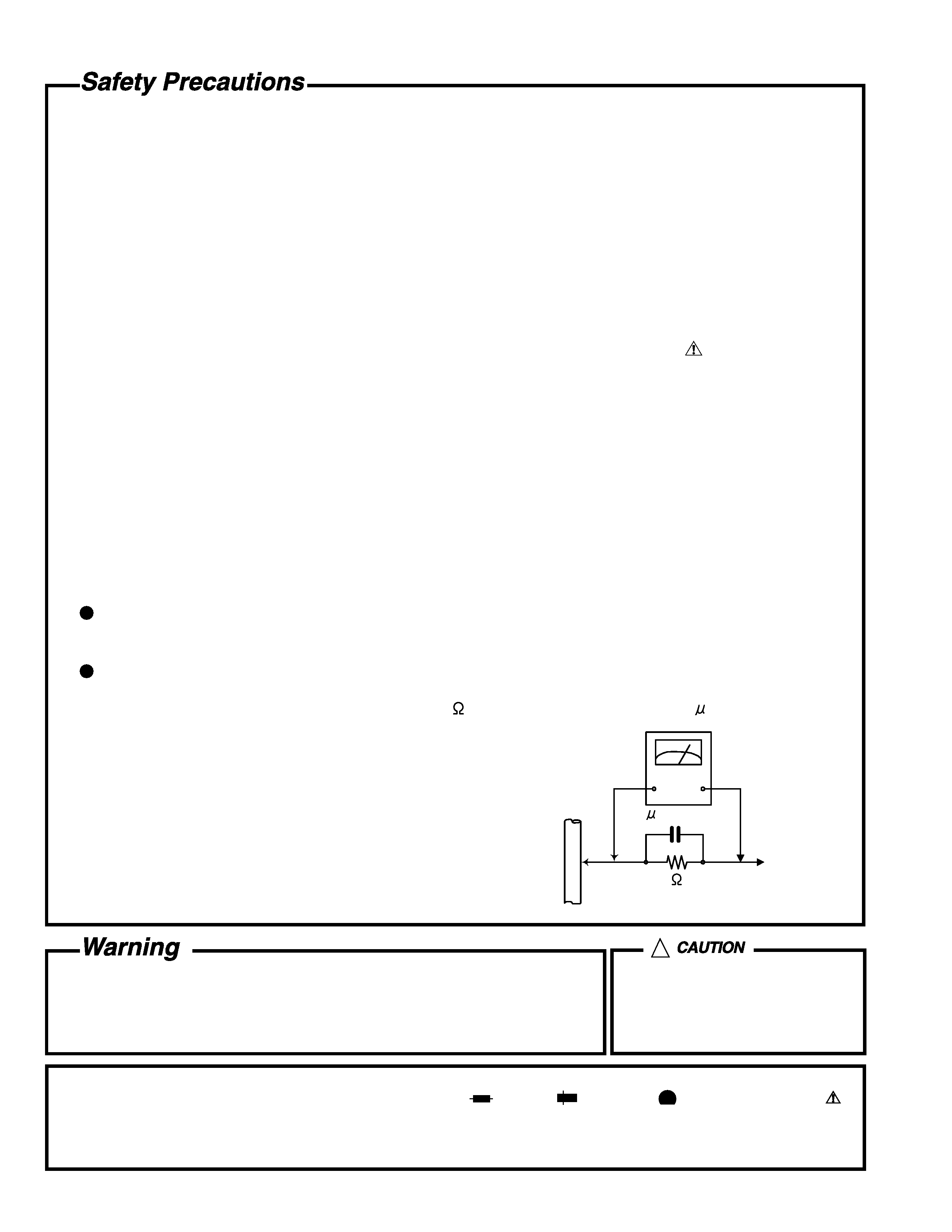
Alternate check method
Plug the AC line cord directly into the AC outlet. Use an AC voltmeter having, 1,000 ohms per volt or more
sensitivity in the following manner. Connect a 1,500
10W resistor paralleled by a 0.15 F AC-type capacitor
between an exposed metal part and a known good earth ground.
Measure the AC voltage across the resistor with the AC
voltmeter.
Move the resistor connection to each exposed metal part,
particularly any exposed metal part having a return path to
the chassis, and measure the AC voltage across the resistor.
Now, reverse the plug in the AC outlet and repeat each
measurement. Voltage measured any must not exceed 0.75 V
AC (r.m.s.). This corresponds to 0.5 mA AC (r.m.s.).
1. This equipment has been designed and manufactured to meet international safety standards.
2. It is the legal responsibility of the repairer to ensure that these safety standards are maintained.
3. Repairs must be made in accordance with the relevant safety standards.
4. It is essential that safety critical components are replaced by approved parts.
5. If mains voltage selector is provided, check setting for local voltage.
Good earth ground
Place this
probe on
each exposed
metal part.
AC VOLTMETER
(Having 1000
ohms/volts,
or more sensitivity)
1500
10W
0.15 F AC TYPE
!
Burrs formed during molding may
be left over on some parts of the
chassis. Therefore, pay attention to
such burrs in the case of
preforming repair of this system.
In regard with component parts appearing on the silk-screen printed side (parts side) of the PWB diagrams, the
parts that are printed over with black such as the resistor (
), diode (
) and ICP (
) or identified by the " "
mark nearby are critical for safety.
When replacing them, be sure to use the parts of the same type and rating as specified by the manufacturer.
(Except the J and C version)
XV-LTR1
1-3
Preventing static electricity
Electrostatic discharge (ESD), which occurs when static electricity stored in the body, fabric, etc. is discharged,
can destroy the laser diode in the traverse unit (optical pickup). Take care to prevent this when performing repairs.
1.1. Grounding to prevent damage by static electricity
Static electricity in the work area can destroy the optical pickup (laser diode) in devices such as DVD players.
Be careful to use proper grounding in the area where repairs are being performed.
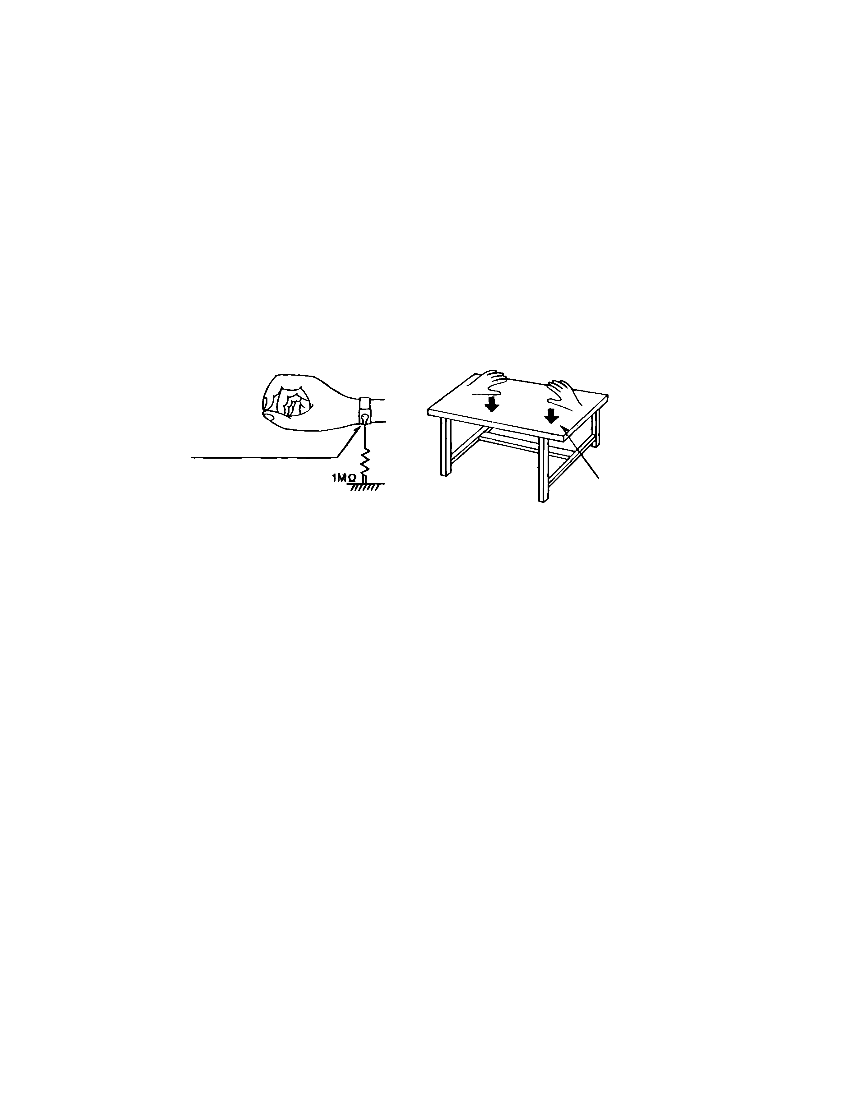
1.1.1. Ground the workbench
1. Ground the workbench by laying conductive material (such as a conductive sheet) or an iron plate over
it before placing the traverse unit (optical pickup) on it.
1.1.2. Ground yourself
1. Use an anti-static wrist strap to release any static electricity built up in your body.
1.1.3. Handling the optical pickup
1. In order to maintain quality during transport and before installation, both sides of the laser diode on the
replacement optical pickup are shorted. After replacement, return the shorted parts to their original condition.
(Refer to the text.)
2. Do not use a tester to check the condition of the laser diode in the optical pickup. The tester's internal power
source can easily destroy the laser diode.
1.2. Handling the traverse unit (optical pickup)
1. Do not subject the traverse unit (optical pickup) to strong shocks, as it is a sensitive, complex unit.
2. Cut off the shorted part of the flexible cable using nippers, etc. after replacing the optical pickup. For specific
details, refer to the replacement procedure in the text. Remove the anti-static pin when replacing the traverse
unit. Be careful not to take too long a time when attaching it to the connector.
3. Handle the flexible cable carefully as it may break when subjected to strong force.
4. It is not possible to adjust the semi-fixed resistor that adjusts the laser power. Do not turn it
Conductive material
(conductive sheet) or iron plate
(caption)
Anti-static wrist strap
XV-LTR1
1-4
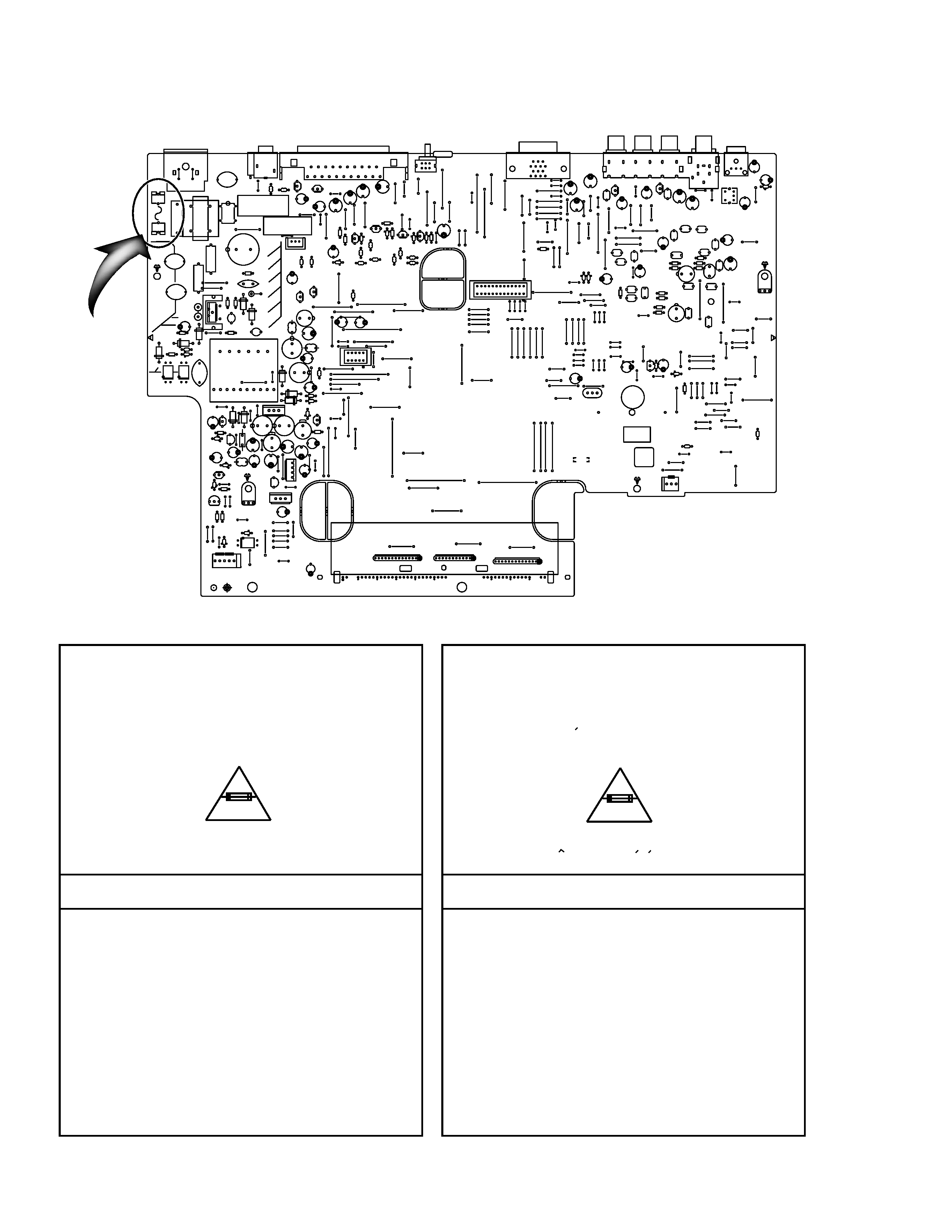
Full Fuse Replacement Marking
Graphic symbol mark
(This symbol means fast blow type fuse.)
should be read as follows ;
FUSE CAUTION
FOR CONTINUED PROTECTION AGAINST RISK
OF FIRE, REPLACE ONLY WITH SAME TYPE
AND RATING OF FUSES ;
F901 : 1.6 A / 125 V
F901 : 1.6 A / 125 V
Marquage Pour Le Remplacement
Complet De Fusible
PRECAUTIONS SUR LES FUSIBLES
POUR UNE PROTECTION CONTINUE CONTRE
DES RISQUES D'INCENDIE, REMPLACER
SEULEMENT PAR UN FUSIBLE DU MEME TYPE ;
Le symbole graphique (Ce symbole signifie
fusible de type a fusion rapide.)
doit etre interprete comme suit ;
Importance Admistering point on the Safety
F901
B7048
B7140
B7125
B7131
B7130
B7129
B7128
B7034
B7058
B7052
B7053
B7036
B7035
B7033
B7032
B7029
B7030
B7031
B7023
B7022
B7203
B7204
B7135
B7136
B7116
B7114
B7115
B7142
B7222
B7025
B7028
B7026
B7024
B7117
B7118
B7113
B7112
B7201
B7202
B7303
B7302
B7301
B7304
B7057
B7401
B7305
B7306
B7307
B7308
B7309
B7606
B7501
B7021
B7219
B7218
B7134
B7012
B7011
B7010
B7016
B7020
K709
B7608
B7605
B5503
B7411
B7412
B7413
B7414
B7415
B7416
B5715
B7325
B7326
B7327
B7328
B7056
B7003
B7002
B7001
B7004
B7005
B7006
B7007
B7008
B7009
B7013
B7014
B7141
B7015
B7107
B7324
B7321
B7322
B7330
B5708
B5707
B7111
B5702
B7104
B7103
B7105
B7102
B7106
B7019
B7017
B7101
B7018
B7137
B7133
B7132
B7409
B7808
B7809
B7810
B7807
B7213
B7317
B7316
B7315
B7408
B7407
B7212
B7806
B7602
B7050
B7803
B5302
B5301
B7406
B7601
B5201
B5202
B7802
CN555
B5102
B7405
B7210
B7209
B7208
B7311
B7122
B7139
B7123
B7502
B7607
B7207
C11
C12
C13
C14
C15
C16
C1701
C1702
C17
C421
C422
C609
C619
C629
C649
C659
C701
C707
C711
C714
C716
C717
C718
C728
C730
C731
C740
C741
C742
C744
C745
C746
C747
C750
C751
C752
C754
C755
C756
C757
C761
C762
C771
C772
C821
C902
C907
C914
C918
C960
C962
C963
C964
C965
C966
C969
C973
C978
C979
C982
C984
C985
C987
C989
C992
C995
C996
C997
CN701
CN702
CN703
CP951
CP952
D609
D619
D629
D639
D701
D702
D709
D791
D792
D901
D902
D903
D904
D908
D910
D911
D950
D951
D952
D953
D954
D956
D957
D960
D970
D972
D973
D974
D991
DI801
EP711
EP951
FC901
FC902
IC702
IC901
IC951
IC953
J601
J602
J603
J702
J703
K902
B7054
L1
L2
L601
L602
L611
L612
L621
L622
L631
L632
L709
L901
L951
L952
L955
L957
L959
P901
Q1
Q601
Q611
Q621
Q631
Q743
Q753
Q951
Q953
Q965
Q966
Q991
R1730
R1732
R606
R616
R636
R650
R740
R741
R742
R743
R745
R750
R751
R752
R753
R755
R901
R903
R904
R905
R906
R907
R908
R910
R911
R953
R954
R956
R960
R976
R980
T701
T901
X701
C906
C908
C909
C913
C916
PC901
PC902
C694
C695
C696
C697
C715
C721
C729
C737
C738
C739
C749
J604
J691
L710
Q744
Q754
R1731
RA701
RA702
RA703
S691
C905
B7206
B7120
,B7119
B7951
B7801
B7403
B7402
B7221
B7312
B7124
B7313
B7314
B7211
B7320
B7051
B7038
B7039
B7040
B7041
B7037
B7042
B7319
B7046
B7043
B7044
B7049
B7045
B7329
B7126
B7127
CN961
B5502
B5501
B5504
B5505
B5506
B5205
B5104
B5152
B7217
B5714
B5101
B5303
B5304
B5305
B5107
B5718
B5705
B5706
B5704
B5703
B5108
B5109
B5507
B5508
B5105
B5720
B5106
B5701
B5153
PC30
D31
D30
B5511
B5719
B5512
B5517
B5513
B5509
B5721
HS901
B7410
B5113
B5112
B5111
B5110
B7604
B5115
B5713
B5114
B7055
B5514
B5157
B5154
B5515
B5710
B5116
B5155
B5709
B5151
B5203
B5156
B7214
C904
XV-LTR1
1-5
Precautions for Service
Handling of Traverse Unit and Laser Pickup
1. Do not touch any peripheral element of the pickup or the actuator.
2. The traverse unit and the pickup are precision devices and therefore must not be subjected to
strong shock.
3. Do not use a tester to examine the laser diode. (The diode can easily be destroyed by the
internal power supply of the tester.)
4. To replace the traverse unit, pull out the metal short pin for protection from charging.
5. When replacing the pickup, after mounting a new pickup, remove the solder on the short land
which is provided at the center of the flexible wire to open the circuit.
6. Half-fixed resistors for laser power adjustment are adjusted in pairs at shipment to match the
characteristics of the optical block.
Do not change the setting of these half-fixed resistors for laser power adjustment.
Destruction of Traverse Unit and Laser Pickup by Static Electricity
Laser diodes are easily destroyed by static electricity charged on clothing
or the human body. Before repairing peripheral elements of the traverse
unit or pickup, be sure to take the following electrostatic protection:
1. Wear an antistatic wrist wrap.
2. With a conductive sheet or a steel plate on the workbench on which
the traverse unit or the pick up is to be repaired, ground the sheet
or the plate.
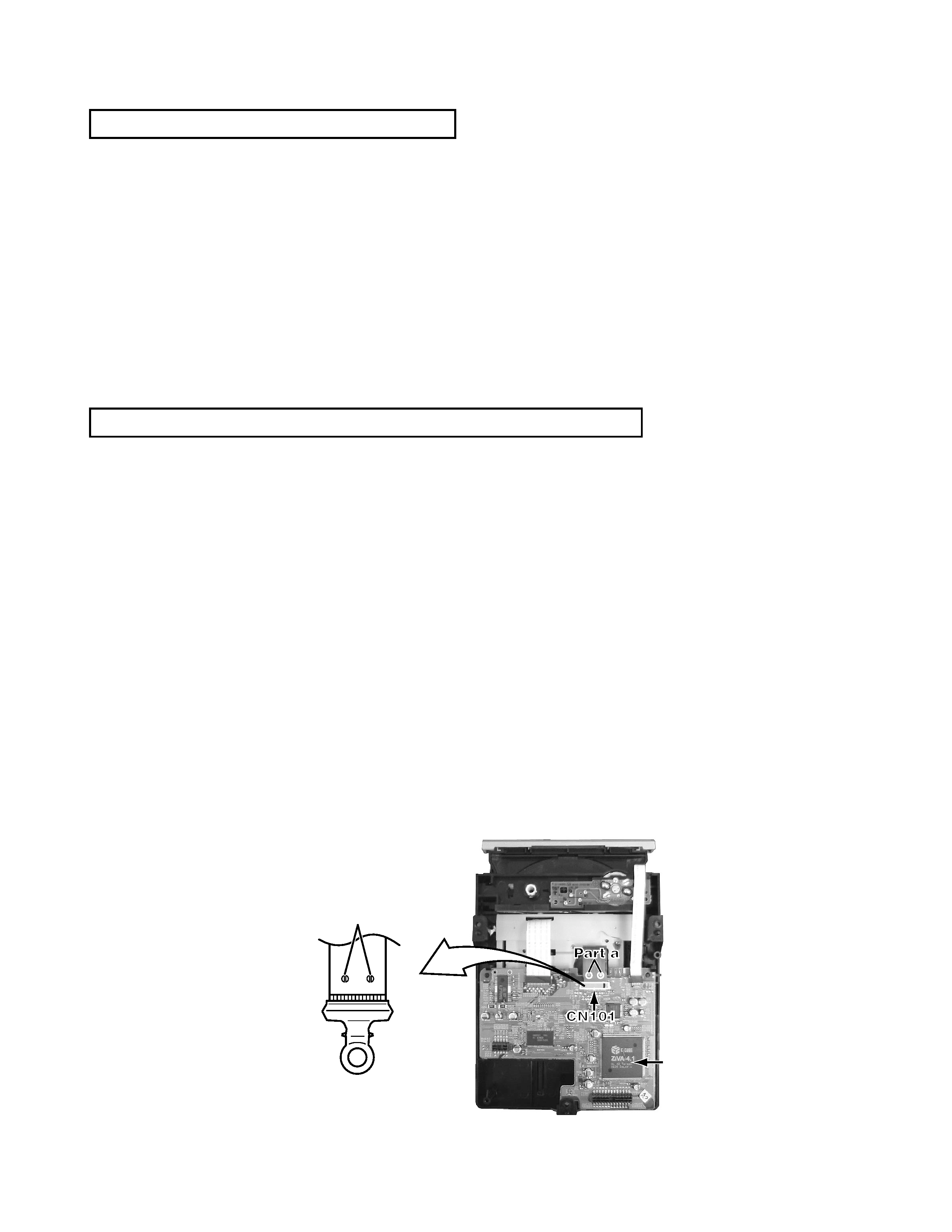
3. After removing the flexible wire from the connector (CN101),
short-circuit the flexible wire by the metal clip.
4. Short-circuit the laser diode by soldering the land which is provided
at the center of the flexible wire for the pickup.
After completing the repair, remove the solder to open the circuit.
Please refer to "Fig.4" of "Disassembly
method" for details.
Short circuit
Servo control
board