SERVICE MANUAL
PORTABLE MINIDISC PLAYER
No.20897
Jan. 2001
COPYRIGHT
2001 VICTOR COMPANY OF JAPAN, LTD.
XM-PX70WT/BU/PN
XM-PX70WT/BU/PN
Area Suffix
UB
Hong Kong
Contents
Safety Precautions
Attention when
MD pick up is exchanged
Disassembly method
Adjustment method
Maintenance of laser pickup
Replacement of laser pickup
Description of major ICs
Attention when parts
are exchanged
1-2
1-3
1-4
1-9
1-10
1-10
1-11
1-24
XM-PX70WT/BU/PN
1-2
1. This design of this product contains special hardware and many circuits and components specially
for safety purposes.
For continued protection, no changes should be made to the original design
unless authorized in writing by the manufacturer.
Replacement parts must be identical to those
used in the original circuits.
Services should be performed by qualified personnel only.
2. Alterations of the design or circuitry of the product should not be made.
Any design alterations of
the product should not be made.
Any design alterations or additions will
void the manufacturer`s
warranty and will further relieve the manufacture of responsibility for personal injury or property
damage resulting therefrom.
3. Many electrical and mechanical parts in the products have special safety-related characteristics.
These characteristics are often not evident from visual inspection nor can the protection afforded
by them necessarily be obtained by using replacement components rated for higher voltage,
wattage, etc.
Replacement parts which have these special safety characteristics are identified in
the Parts List of Service Manual.
Electrical components having such features are identified by
shading on the schematics and by (
) on the Parts List in the Service Manual.
The use of a
substitute replacement which does not have the same safety characteristics as the recommended
replacement parts shown in the Parts List of Service Manual may create shock, fire, or other
hazards.
4. The leads in the products are routed and dressed with ties, clamps, tubings, barriers and the
like to be separated from live parts, high temperature parts, moving parts and/or sharp edges
for the prevention of electric shock and fire hazard.
When service is required, the original lead
routing and dress should be observed, and it should be confirmed that they have been returned
to normal, after re-assembling.
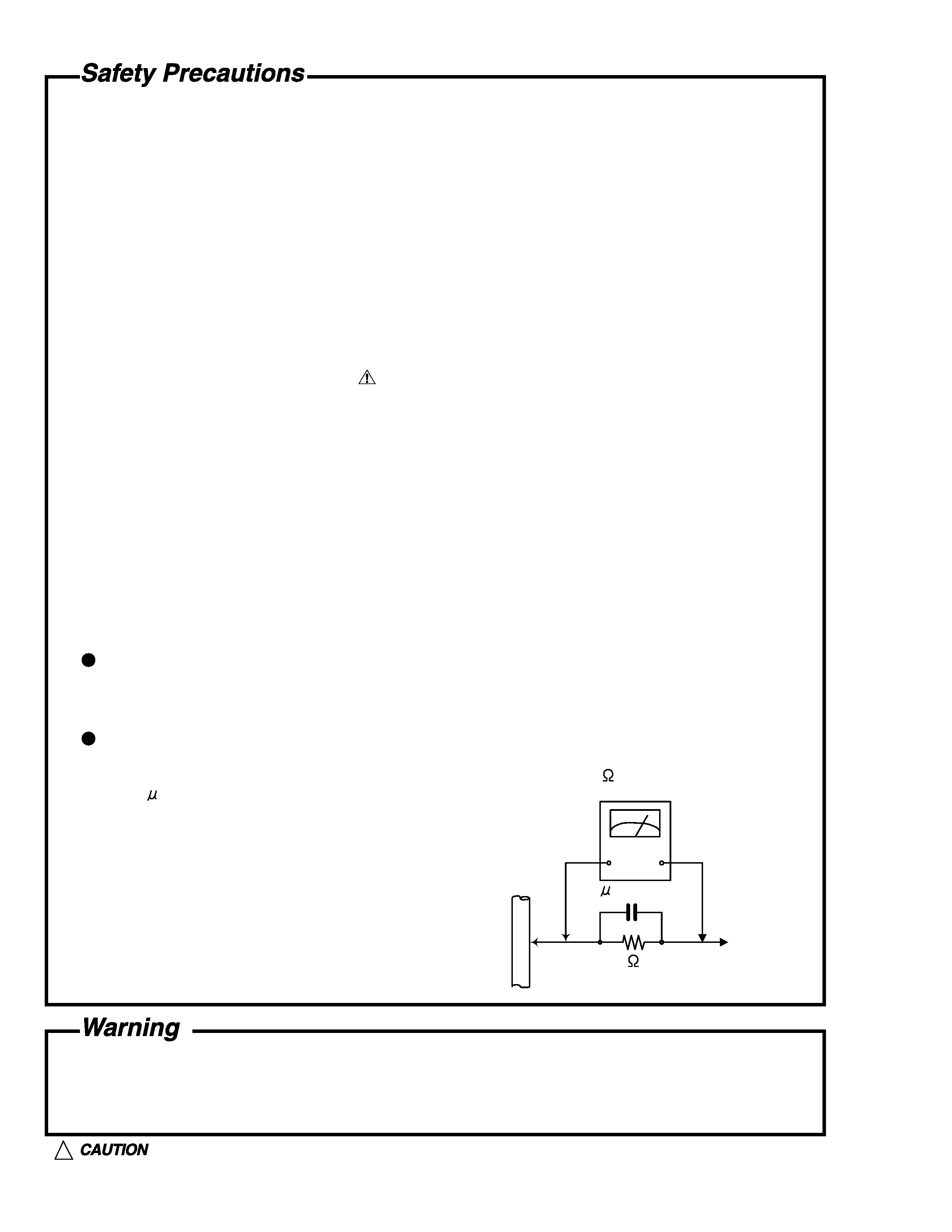
5. Leakage currnet check (Electrical shock hazard testing)
After re-assembling the product, always perform an isolation check on the exposed metal parts
of the product (antenna terminals, knobs, metal cabinet, screw heads, headphone jack, control
shafts, etc.) to be sure the product is safe to operate without danger of electrical shock.
Do not use a line isolation transformer during this check.
Plug the AC line cord directly into the AC outlet.
Using a "Leakage Current Tester", measure
the leakage
current from each exposed metal parts of the cabinet , particularly any exposed
metal part having a return path to the chassis, to a known good earth ground. Any leakage
current must not exceed 0.5mA AC (r.m.s.)
Alternate check method
Plug the AC line cord directly into the AC outlet.
Use an AC voltmeter having, 1,000 ohms
per volt or more sensitivity in the following manner. Connect a 1,500
10W resistor paralleled by
a 0.15 F AC-type capacitor between an exposed
metal part and a known good earth ground.
Measure the AC voltage across the resistor with the
AC voltmeter.
Move the resistor connection to eachexposed metal
part, particularly any exposed metal part having a
return path to the chassis, and meausre the AC
voltage across the resistor. Now, reverse the plug in
the AC outlet and repeat each measurement. voltage
measured Any must not exceed 0.75 V AC (r.m.s.).
This corresponds to 0.5 mA AC (r.m.s.).
1. This equipment has been designed and manufactured to meet international safety standards.
2. It is the legal responsibility of the repairer to ensure that these safety standards are maintained.
3. Repairs must be made in accordance with the relevant safety standards.
4. It is essential that safety critical components are replaced by approved parts.
5. If mains voltage selector is provided, check setting for local voltage.
Good earth ground
Place this
probe on
each exposed
metal part.
AC VOLTMETER
(Having 1000
ohms/volts,
or more sensitivity)
1500
10W
0.15 F AC TYPE
!
Burrs formed during molding may be left over on some parts of the chassis. Therefore,
pay attention to such burrs in the case of preforming repair of this system.
XM-PX70WT/BU/PN
1-3
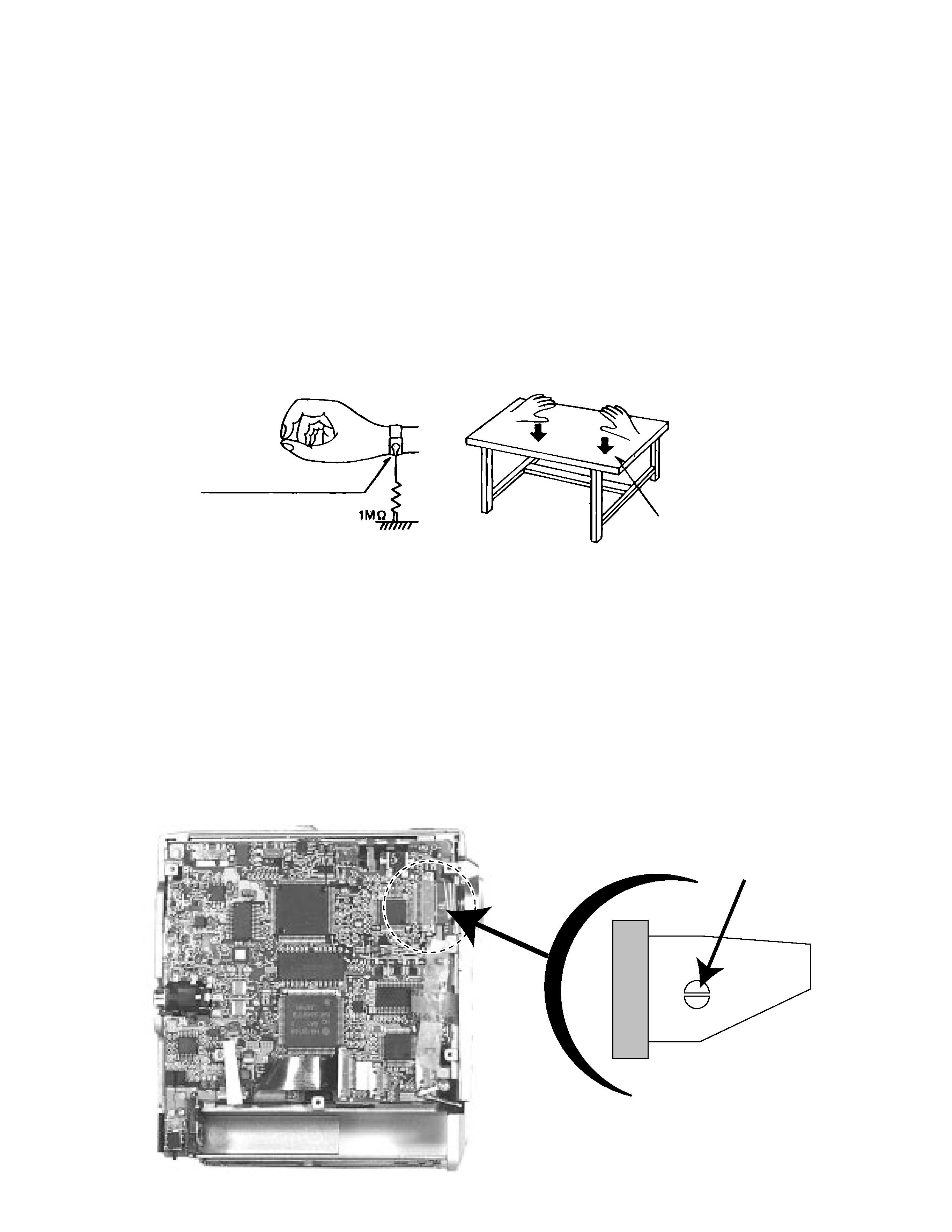
The laser diode in the traverse unit (optical pick up) is easy to be destroyed by clothes and the human body
to the electrified static electricity.
Please note the explosion by static electricity when repairing.
In the equipment which uses an optical pick up (laser diode), an optical pick up is destroyed by the static
electricity of the work environment.
Please do the earth processing and work.
2. About the earth processing for the electrostatic destruction prevention
1) Earth of work stand
Please pull the conductive material (conductive sheet) or the iron plate to the depository
place of the traverse unit (optical pick up), and take the earth to ground.
2) Human body earth
Please use the anti-static wrist strap to exhaust the electrified static electricity to the human body.
3.
Handling the optical pick up
1) Please return according to a correct procedure based on short processing after exchanging
parts.
2) Do not use a tester to check the condition of the laser diode in the optical pick up .The tester 's internal
power source can easily destroy the laser diode.
4. Attention when unit is disassembled
Please refer to "Disassembling method" for how to detach .
Conductive material (conductive
sheet) or the iron plate
anti-static wrist strap
Attention when MD pickup is exchanged
1. About the static electricity protection measures
Solder short
1) Please be sure to solder before a flexible wire is removed from connector on a main printed
circuit board as shown.
if you removes without soldering.the MD picking up assembly might destroy
2) When installing , solder in the part of short round should be removed after a flexible wire is connected with
connector.
XM-PX70WT/BU/PN
1-4
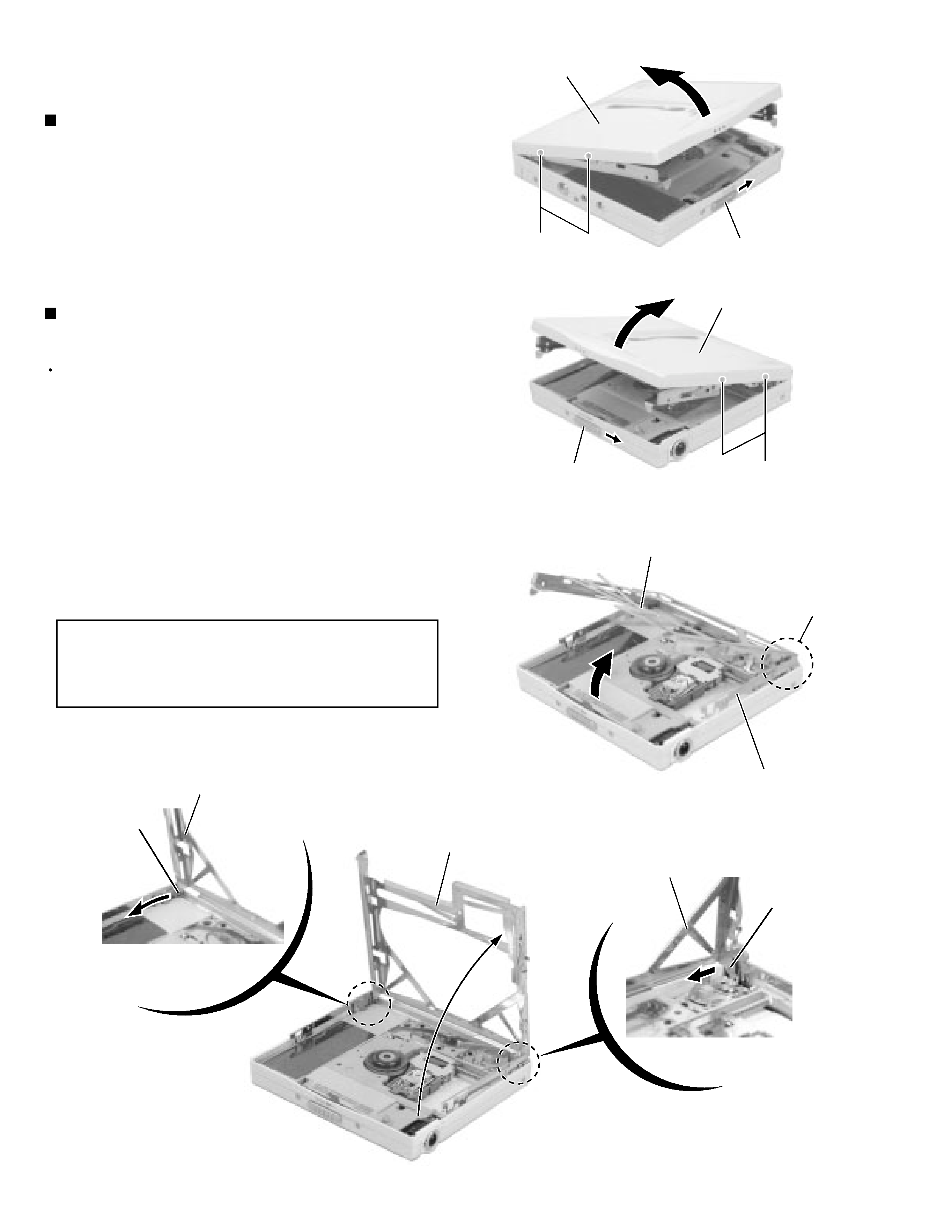
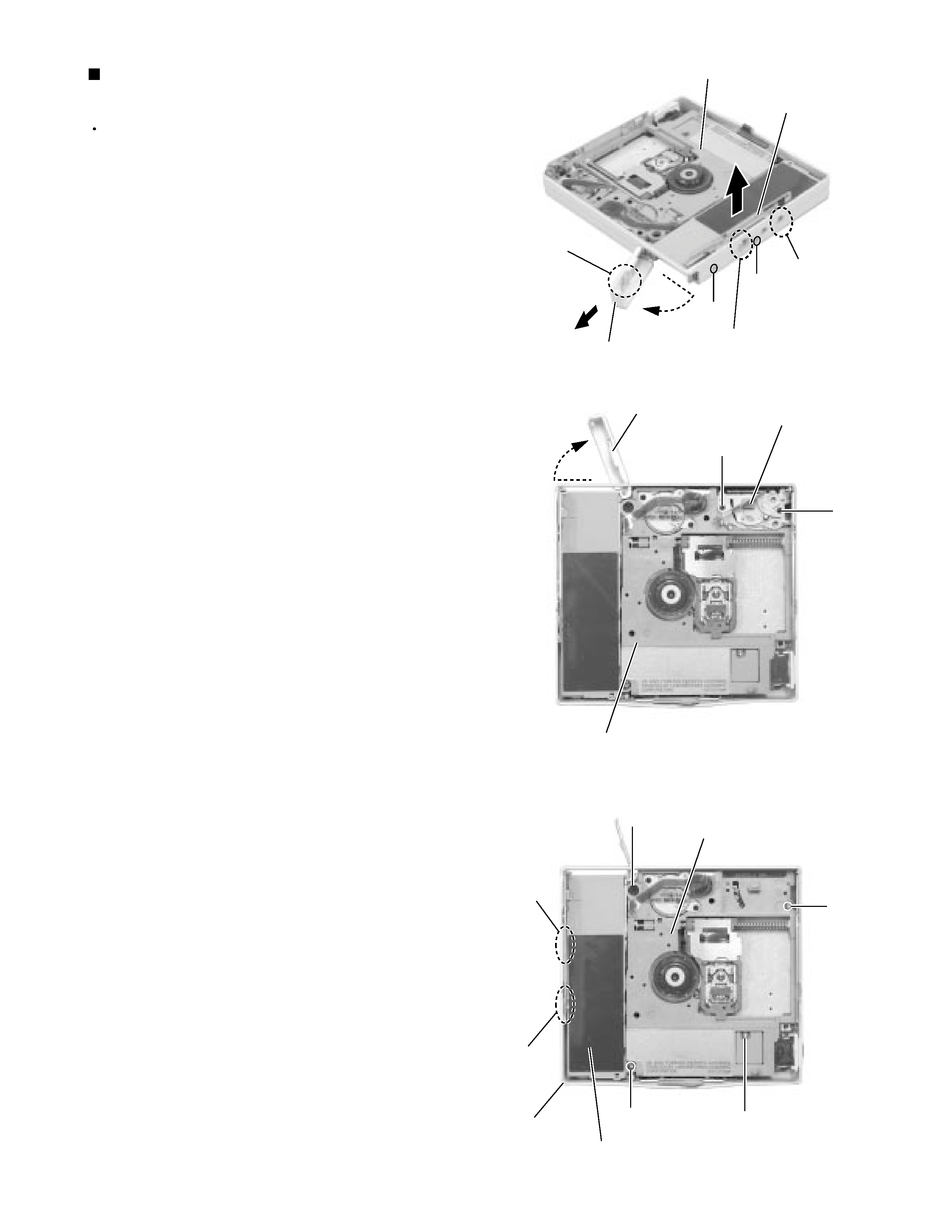
Shift the door lever to open the door.
Remove the four screws A and detach the MD door
assembly from the main body.
1.
2.
Disassembly method
Removing the MD door assembly
(See Fig.1 and 2)
Prior to performing the following procedure, remove
the MD door assembly.
Turn the holder assembly as shown in Fig.3.
Pull the side arm (L) marked a and remove outward.
Open the holder assembly as
shown in Fig.4.
Move the marked b in the direction of the arrow and
release it from the shaft.
Move the part c inward and pull out the holder
assembly from the shaft.
1.
2.
3.
4.
Removing the holder assembly
(See Fig.3 and 4)
When reassembling, first reattach the
part c to the shaft of the chassis
assembly. And next, fit the "U-shaped"
notch to the shaft.
ATTENTION:
MD door assembly
MD door assembly
Door lever
Door lever
A
A
Fig.1
Fig.2
Fig.3
Fig.4
Holder assembly
Part a
Part b
"U-shaped" notch
Part c shaft
Side arm (L)
Holder assembly
Holder assembly
Holder assembly
Part c
XM-PX70WT/BU/PN
1-5
Prior to performing the following procedure, remove
the MD door assembly and the holder assembly.
Open the battery lid. Release the tab d and pull out
the battery lid.
Remove the screw B and pull out the side arm (R)
upward.
Remove the two screws C and pull out the eject unit.
Remove the screw D, E, F, G and H attaching the
chassis assembly respectively.
Disengage the three joints e of the bottom case and
the battery holder. Remove the chassis assembly
and the jack cover at once.
1.
2.
3.
4.
5.
Removing the chassis assembly
(See Fig.5 to 7)
Fig.5
Fig.6
Fig.7
Chassis assembly
Side arm (R)
Battery lid
Tab d
Joint e
Joint e
D
B
Battery lid
Chassis assembly
C
Eject unit
C
Chassis assembly
Joint e
Joint e
H
E
G
F
Bottom case
Battery holder