SERVICE MANUAL
SD AUDIO PLAYER
No.21010
Jul. 2001
COPYRIGHT
2001 VICTOR COMPANY OF JAPAN, LTD.
XA-SD1
XA-SD1
Contents
Safety precautions
Disassembly method
Troubleshooting
Flowchart
1-2
1-3
1-5
1-6
All parts except the chassis are replaced by unit component. (The block,
circuit and board diagrams are not described in this service manual.)
Area Suffix
J ------------- U.S.A.
SD
AUDIO
PLA
YER
XA-SD1
VOLU
ME
XA-SD1
1-2
1. This design of this product contains special hardware and many circuits and components specially for safety
purposes. For continued protection, no changes should be made to the original design unless authorized in
writing by the manufacturer. Replacement parts must be identical to those used in the original circuits. Services
should be performed by qualified personnel only.
2. Alterations of the design or circuitry of the product should not be made. Any design alterations of the product
should not be made. Any design alterations or additions will void the manufacturer`s warranty and will further
relieve the manufacture of responsibility for personal injury or property damage resulting therefrom.
3. Many electrical and mechanical parts in the products have special safety-related characteristics. These
characteristics are often not evident from visual inspection nor can the protection afforded by them necessarily
be obtained by using replacement components rated for higher voltage, wattage, etc. Replacement parts which
have these special safety characteristics are identified in the Parts List of Service Manual. Electrical
components having such features are identified by shading on the schematics and by (
) on the Parts List in
the Service Manual. The use of a substitute replacement which does not have the same safety characteristics
as the recommended replacement parts shown in the Parts List of Service Manual may create shock, fire, or
other hazards.
4. The leads in the products are routed and dressed with ties, clamps, tubings, barriers and the like to be
separated from live parts, high temperature parts, moving parts and/or sharp edges for the prevention of
electric shock and fire hazard. When service is required, the original lead routing and dress should be
observed, and it should be confirmed that they have been returned to normal, after re-assembling.
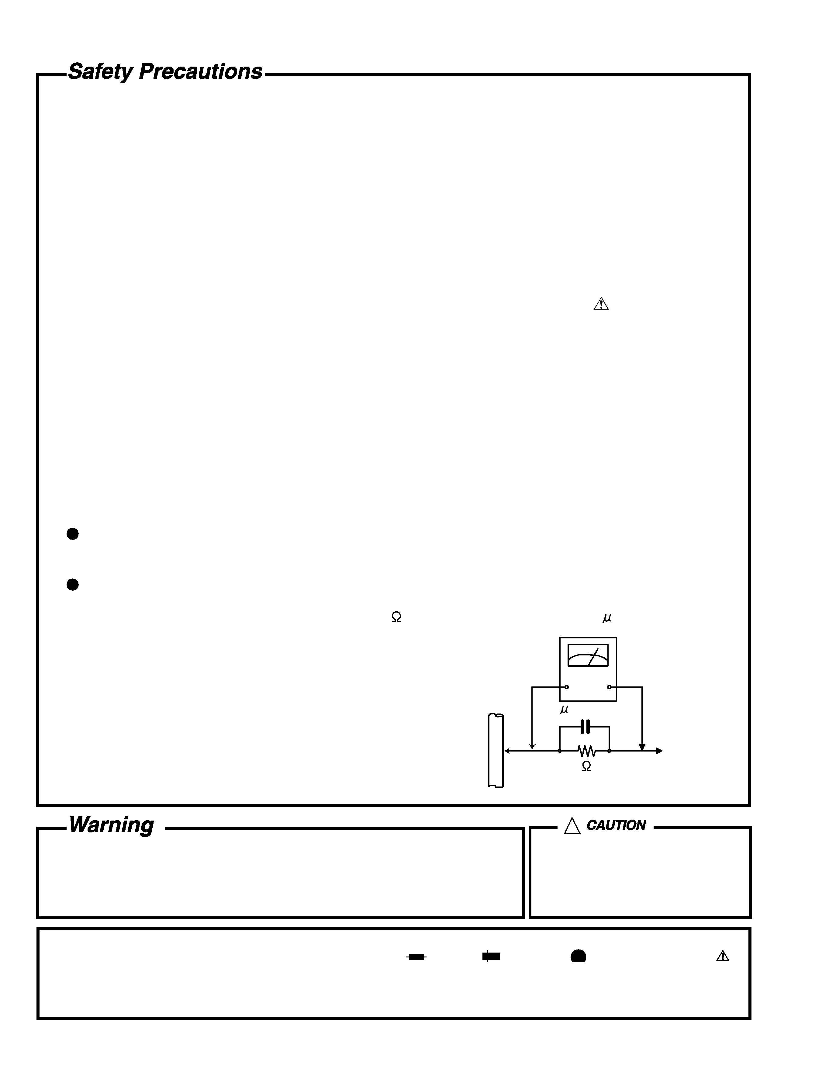
5. Leakage currnet check (Electrical shock hazard testing)
After re-assembling the product, always perform an isolation check on the exposed metal parts of the product
(antenna terminals, knobs, metal cabinet, screw heads, headphone jack, control shafts, etc.) to be sure the
product is safe to operate without danger of electrical shock.
Do not use a line isolation transformer during this check.
Plug the AC line cord directly into the AC outlet. Using a "Leakage Current Tester", measure the leakage
current from each exposed metal parts of the cabinet, particularly any exposed metal part having a return
path to the chassis, to a known good earth ground. Any leakage current must not exceed 0.5mA AC (r.m.s.).
Alternate check method
Plug the AC line cord directly into the AC outlet. Use an AC voltmeter having, 1,000 ohms per volt or more
sensitivity in the following manner. Connect a 1,500
10W resistor paralleled by a 0.15 F AC-type capacitor
between an exposed metal part and a known good earth ground.
Measure the AC voltage across the resistor with the AC
voltmeter.
Move the resistor connection to eachexposed metal part,
particularly any exposed metal part having a return path to
the chassis, and meausre the AC voltage across the resistor.
Now, reverse the plug in the AC outlet and repeat each
measurement. Voltage measured any must not exceed 0.75 V
AC (r.m.s.). This corresponds to 0.5 mA AC (r.m.s.).
1. This equipment has been designed and manufactured to meet international safety standards.
2. It is the legal responsibility of the repairer to ensure that these safety standards are maintained.
3. Repairs must be made in accordance with the relevant safety standards.
4. It is essential that safety critical components are replaced by approved parts.
5. If mains voltage selector is provided, check setting for local voltage.
Good earth ground
Place this
probe on
each exposed
metal part.
AC VOLTMETER
(Having 1000
ohms/volts,
or more sensitivity)
1500
10W
0.15 F AC TYPE
!
Burrs formed during molding may
be left over on some parts of the
chassis. Therefore, pay attention to
such burrs in the case of
preforming repair of this system.
In regard with component parts appearing on the silk-screen printed side (parts side) of the PWB diagrams, the
parts that are printed over with black such as the resistor (
), diode (
) and ICP (
) or identified by the " "
mark nearby are critical for safety.
When replacing them, be sure to use the parts of the same type and rating as specified by the manufacturer.
(Except the J and C version)
XA-SD1
1-3
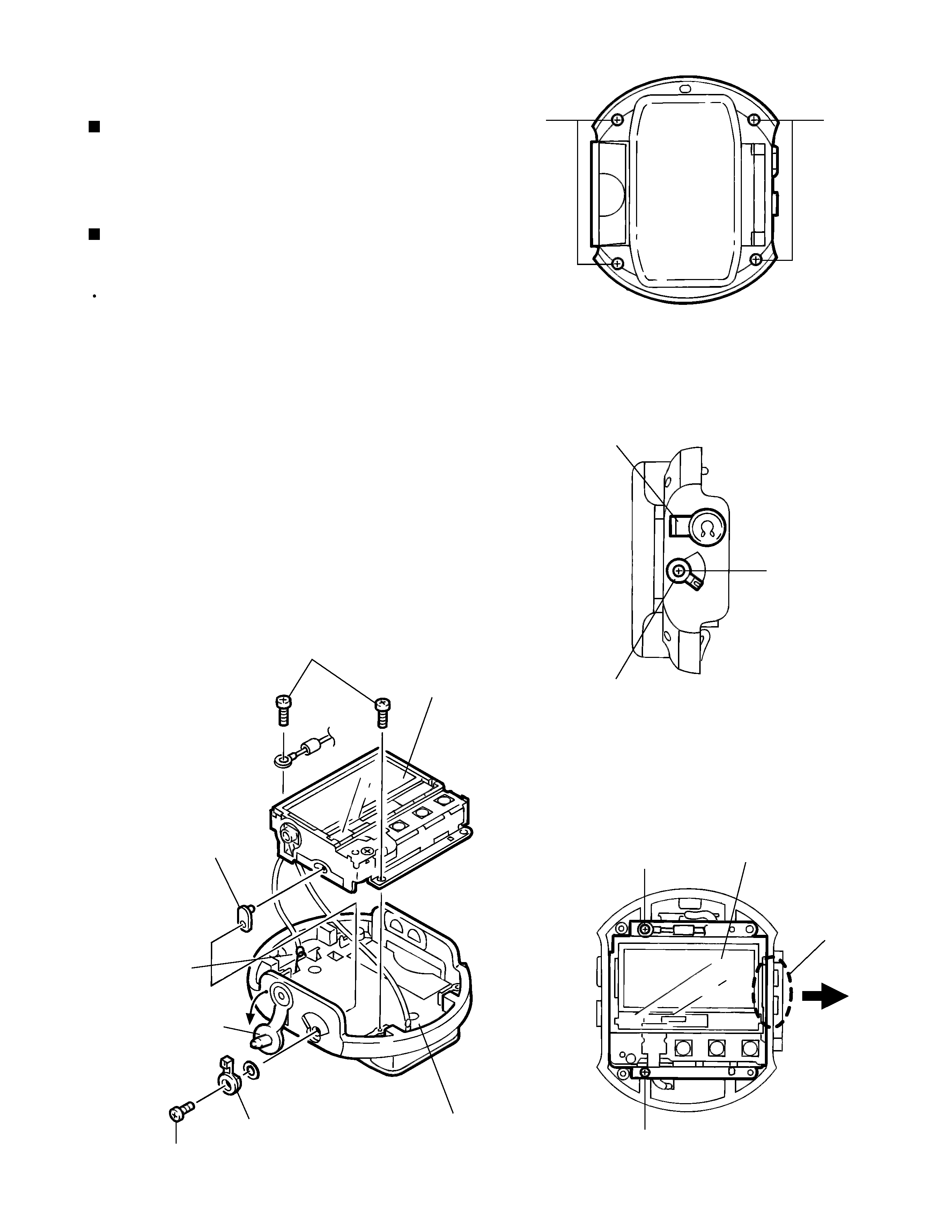
Remove four screws A retaining the metallic cover
from the bottom of the unit.
1.
Disassembly method
Removing the metallic cover (Fig. 1)
Remove the metallic cover before proceeding to the
following.
1.Remove the headphone cover from the left side
panel.
2.Remove screw B attaching the mode switch lever
from the left side panel, and then remove the mode
switch lever.
3.Remove two screws C retaining the main board from
the top of the unit.
4.Expand engagement a between the VOLUME switch
and right side panel outward and take out the unit.
The switch lever on the left side of the Main Board
willcome out at this time.
5.Remove solder from the two wire soldering positions
on the main board ass'y.
Removing the main board ass'y
(Figs. 2 to 4)
Fig.1
Fig.2
Fig. 3
Fig. 4
A
A
(Bottom panel)
B
Headphone cover
Mode switch lever
Engagement a
Main board ass'y
C
C
Switch lever
Main board ass'y
Mode switch lever
B
C
Headphone cover
Soldering
position
Soldering
position
XA-SD1
1-4
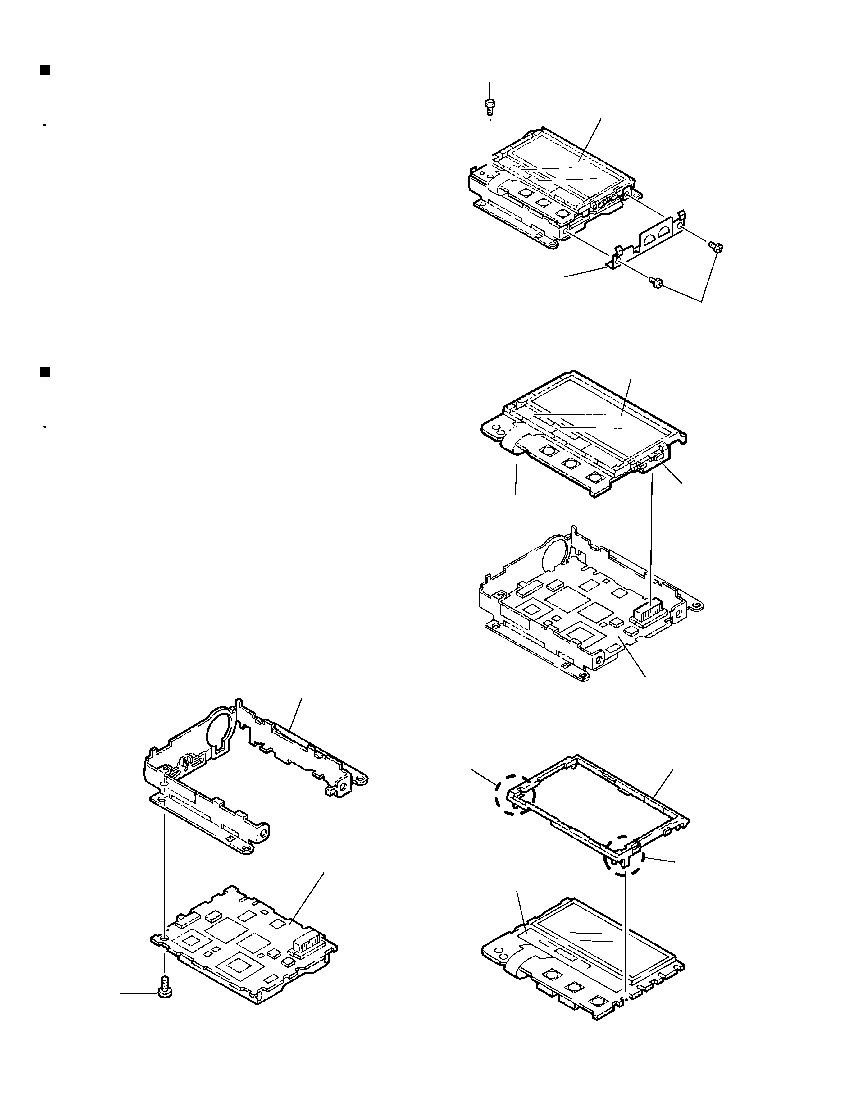
Remove the main board ass'y before proceeding to
the following.
1.Remove two screws D retaining the side bracket from
the right side of the main board ass'y.
Remove screw E retaining the LCD board from the top
of the main board ass'y, and disconnect connector
CN501 from the sub board by pulling the connector
upward.
Expand two claws b on the holder outward and
remove the holder from the LCD Board.
Removing the main board ass'y
(Figs. 2 to 4)
Remove the main board ass'y before proceeding to
the following.
Remove the LCD board before proceeding to the
following.
1.Remove screw F retaining the sub board from its
bottom.
Removing the main board ass'y
(Figs. 2 to 4)
Fig. 5
Fig. 6
Fig. 7
Fig. 8
Main board ass'y
E
Side bracket
D
LCD board
CN501
Connector CN501
Sub board
Holder
LCD board
Sub board
Unit
F
Claw b
Claw b

XA-SD1
1-5
Troubleshooting
A PC that has the exclusive application software (JVC Media Manager V2)installed. Be sure to check for
normal operation of the PC. If other application software is installed in the PC, be sure that this software
does not affect the operation of the JVC Media Manager V2.
When a user's product is taken in for service, be sure to obtain not only the player but also the user's SD
card and USB reader/writer. Also, try to obtain as possible on the operational environment of the user's PC.
<PC's operational environment>
Product name, model number, name of CPU, operation clock, RAM capacity, HD capacity, names of
installed software, use of USB hub, and any equipment connected with USB simultaneously.
Checkpoints before servicing
Is the write-protect switch on the SD card set to LOCK?
Does the battery have enough capacity?
Be aware that manganese batteries do not have sufficient capacitor; their use can result in improper
operation.
Precautions
A PC sometimes does not recognize the USB reader/writer depending on its conditions (such as competing
with the installed software). Therefore, always keep the PC in good condition so that any adaptor can be
connected properly.
There is a possibility that not only the hardware but also software (PC's application software) may be the
source of the problem. Therefore, be sure to inspect all potential sources carefully and thoroughly before
specifying any causes.
Check the connection part of the card to see whether it is dirty or has any foreign objects attached to it
before specifying the cause of the problem.
If the card is formatted, the written data (signals) will be erased and cannot be recovered
When you format the card, be sure to format it with the format function of JVC Media Manager V2.
If the card is formatted with Windows or MS-DOS, the card will not operate with JVC Media Manager V2.
What to prepare