COPYRIGHT © 2003 VICTOR COMPANY OF JAPAN, LTD
SERVICE MANUAL
For disassembling and assembling of MECHANISM ASSEMBLY, refer to the SERVICE MANUAL No.86700(MECHANISM ASSEMBLY).
Formato
: Norma NTSC VHS
Alimentación
: DC 9 V
Consumo de energía
: 3,4 W
Sistema de señales
: Tipo NTSC
Sistema de registro de video
Luminancia
: Registro por FM
Color
: Registro directo por
subportadora convertida
Según la norma VHS
Cassette
: Videocassette
Velocidad de la cinta
: 33,35 mm/s
Tiempo máximo de
grabación
: 40 minutos
Temperatura de
funcionamiento
:10
°C a 40°C
Margen de humedad
para funcionamiento : 35% a 80%
Temperatura de
almacenamiento
: 20
°C a 50°C
Peso
: Aprox. 590 g
Algunos accesorios no se encuentran disponibles
en ciertas áreas. Por favor consulte a su agente
más cercano de JVC antes de comprar los
accesorios opcionales.
Los especifiaciones indicadas corresponden al modo SP a menos que se especifique lo contrario. Diseño
y especificaciones sujetos a cambio sin previo aviso.
Accesorios opcionales
· VHS (
) Compacto (cassettes VHS-C)
TC-40/30/20
· Bolso CB-V7U
· Adaptador de Cassete C-P7U
Dimensiones
: 65 mm x 115 mm x
(An x Al x Pr)
182 mm
(con el visor
completamente inclinado
hacia abajo)
Fonocaptor
: CCD de 1/6"
Objetivo
: F3,5, f = 3.2 mm
Ajuste del balance del
blanco
: Automático
No.86744
2003/05
GR-FC1UM,
VU-FC1KUS
GR-FC1UM M3A1
VU-FC1KUS M3ACC
CÁMARA DE VIDEO VHS COMPACTO
ESPECIFICACIONES
- GR-FC1UM -
- VU-FC1KUS -

Important Safety Precautions
INSTRUCTIONS
GR-FC1UM
1. DISASSEMBLY
1.1
BEFORE ASSEMBLY AND DISASSEMBLY ............................ 1-1
1.1.1 Precautions ........................................................................... 1-1
1.1.2 Assembly and disassembly ................................................... 1-1
1.1.3 Destination of connectors ..................................................... 1-1
1.1.4 Disconnection of Connectors (Wires) ................................... 1-1
1.1.5 Tools required for disassembly and assembly ...................... 1-1
1.2
DISASSEMBLY/ASSEMBLY OF CABINET PARTS ................. 1-2
1.2.1 Disassembly flow chart ......................................................... 1-2
1.2.2 Disassembly method ............................................................. 1-2
1.3
EMERGENCY DISPLAY .......................................................... 1-5
1.4
TAKE OUT CASSETTE TAPE ................................................. 1-5
1.5
SERVICE NOTE ...................................................................... 1-6
2. MECHANISM
Refer to the SERVICE MANUAL No.86700(MECHANISM ASSEMBLY)
3. ADJUSTMENT
3.1
PREPARATION ........................................................................ 3-1
3.2
TOOLS REQUIRED FOR ADJUSTMENT ............................... 3-1
3.3
MECHANISM ADJUSTMENT .................................................. 3-3
3.3.1 TAPE TRANSPORT ADJUSTMENT ..................................... 3-3
3.3.2 Back tension ......................................................................... 3-3
3.3.3 Tape pattern .......................................................................... 3-3
3.3.4 A/C head height & azimuth ................................................... 3-4
3.3.5 Phase of control head (X value) ............................................ 3-5
3.4
ELECTRICAL ADJUSTMENT .................................................. 3-6
3.4.1 ELECTRICAL ADJUSTMENT WITH PERSONAL COMPUTER . 3-3
4. CHARTS AND DIAGRAMS
4.1
BOARD INTERCONNECTIONS .............................................. 4-3
4.2
MAIN(CPU) SCHEMATIC DIAGRAM ...................................... 4-5
4.3
MAIN(M.MDA) SCHEMATIC DIAGRAM .................................. 4-7
4.4
MAIN(DSP) SCHEMATIC DIAGRAM ....................................... 4-9
4.5
MAIN(REG) SCHEMATIC DIAGRAM ..................................... 4-11
4.6
MAIN(VTR ASP) SCHEMATIC DIAGRAM ............................. 4-13
4.7
MAIN(TG/CDS) SCHEMATIC DIAGRAM .............................. 4-15
4.8
CCD SCHEMATIC DIAGRAM ................................................ 4-16
4.9
MAIN CIRCUIT BOARD ......................................................... 4-17
4.10 CCD CIRCUIT BOARD .......................................................... 4-21
4.11 POWER SYSTEM BLOCK DIAGRAM ................................... 4-22
4.12 CAMERA AND Y/C SYSTEM BLOCK DIAGRAM .................. 4-23
4.13 CPU/MDA SYSTEM BLOCK DIAGRAM ................................ 4-25
TABLE OF CONTENTS
Section
Title
Page
Section
Title
Page
5. PARTS LIST
5.1 EXPLODED VIEW ...................................................................... 5-1
5.1.1 PACKING AND ACCESSORY ASSEMBLY <M1> ................ 5-1
5.1.2 FINAL ASSEMBLY <M2> ...................................................... 5-2
5.1.3 MECHANISM ASSEMBLY <M3> .......................................... 5-4
5.2 PARTS LIST ................................................................................ 5-5
PACKING AND ACCESSORY PARTS LIST<M1> .......................... 5-5
FINAL PARTS LIST<M2> ................................................................ 5-5
MECHANISM PARTS LIST<M3> .................................................... 5-5
MAIN BOARD ASSEMBLY <01> .................................................... 5-7
CCD BOARD ASSEMBLY <02> ..................................................... 5-9
VU-FC1KUS
6. PARTS LIST
6.1 PACKING AND ACCESSORY ASSEMBLY<M1> ....................... 6-1
Important Safety Precautions
Prior to shipment from the factory, JVC products are strictly inspected to conform with the recognized product safety and electrical codes
of the countries in which they are to be sold. However, in order to maintain such compliance, it is equally important to implement the
following precautions when a set is being serviced.
Fig.1
1. Locations requiring special caution are denoted by labels and
inscriptions on the cabinet, chassis and certain parts of the
product. When performing service, be sure to read and com-
ply with these and other cautionary notices appearing in the
operation and service manuals.
2. Parts identified by the
symbol and shaded (
) parts are
critical for safety.
Replace only with specified part numbers.
Note: Parts in this category also include those specified to com-
ply with X-ray emission standards for products using
cathode ray tubes and those specified for compliance
with various regulations regarding spurious radiation
emission.
3. Fuse replacement caution notice.
Caution for continued protection against fire hazard.
Replace only with same type and rated fuse(s) as specified.
4. Use specified internal wiring. Note especially:
1) Wires covered with PVC tubing
2) Double insulated wires
3) High voltage leads
5. Use specified insulating materials for hazardous live parts.
Note especially:
1) Insulation Tape
3) Spacers
5) Barrier
2) PVC tubing
4) Insulation sheets for transistors
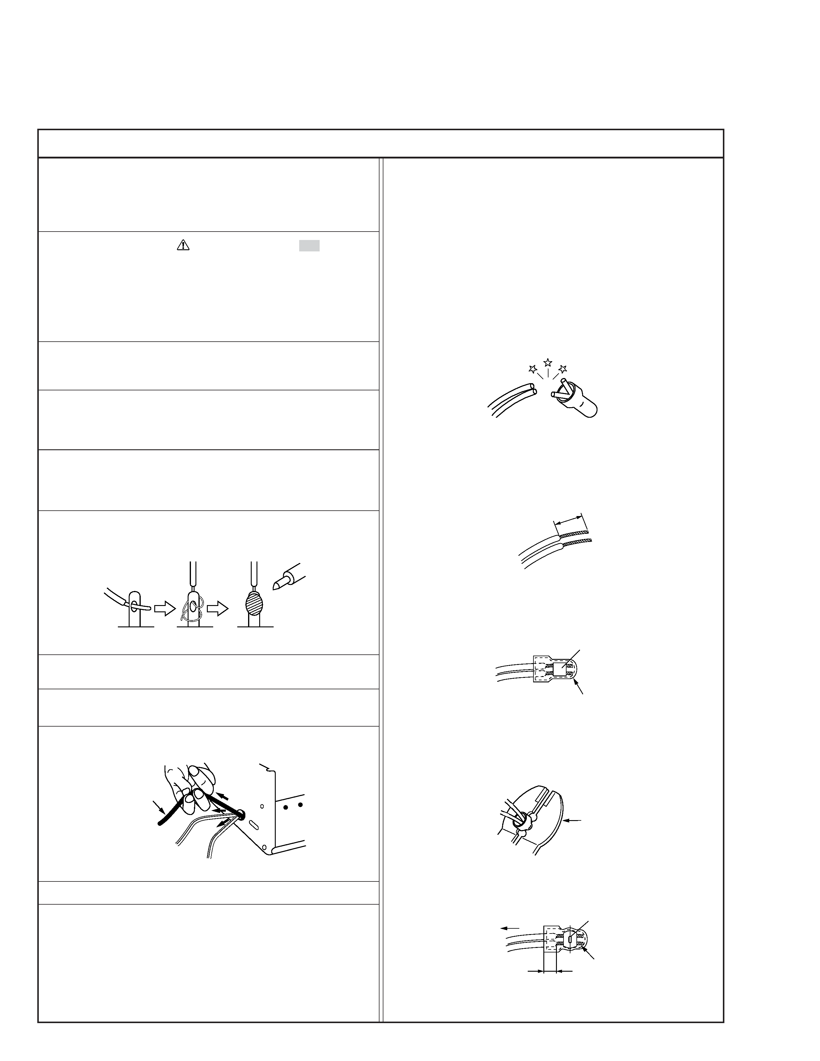
6. When replacing AC primary side components (transformers,
power cords, noise blocking capacitors, etc.) wrap ends of
wires securely about the terminals before soldering.
Power cord
Fig.2
10. Also check areas surrounding repaired locations.
11. Products using cathode ray tubes (CRTs)
In regard to such products, the cathode ray tubes themselves,
the high voltage circuits, and related circuits are specified for
compliance with recognized codes pertaining to X-ray emission.
Consequently, when servicing these products, replace the cath-
ode ray tubes and other parts with only the specified parts.
Under no circumstances attempt to modify these circuits.
Unauthorized modification can increase the high voltage value
and cause X-ray emission from the cathode ray tube.
12. Crimp type wire connector
In such cases as when replacing the power transformer in sets
where the connections between the power cord and power
transformer primary lead wires are performed using crimp type
connectors, if replacing the connectors is unavoidable, in or-
der to prevent safety hazards, perform carefully and precisely
according to the following steps.
1) Connector part number : E03830-001
2) Required tool : Connector crimping tool of the proper type
which will not damage insulated parts.
3) Replacement procedure
(1) Remove the old connector by cutting the wires at a point
close to the connector.
Important : Do not reuse a connector (discard it).
Fig.7
cut close to connector
Fig.3
(2) Strip about 15 mm of the insulation from the ends of
the wires. If the wires are stranded, twist the strands to
avoid frayed conductors.
15 mm
Fig.4
(3) Align the lengths of the wires to be connected. Insert
the wires fully into the connector.
Connector
Metal sleeve
Fig.5
(4) As shown in Fig.6, use the crimping tool to crimp the
metal sleeve at the center position. Be sure to crimp fully
to the complete closure of the tool.
1
Precautions during Servicing
7. Observe that wires do not contact heat producing parts
(heatsinks, oxide metal film resistors, fusible resistors, etc.)
8. Check that replaced wires do not contact sharp edged or
pointed parts.
9. When a power cord has been replaced, check that 10-15 kg of
force in any direction will not loosen it.
1.25
2.0
5.5
Crimping tool
Fig.6
(5) Check the four points noted in Fig.7.
Not easily pulled free
Crimped at approx. center
of metal sleeve
Conductors extended
Wire insulation recessed
more than 4 mm
S40888-01
Safety Check after Servicing
Examine the area surrounding the repaired location for damage or deterioration. Observe that screws, parts and wires have been
returned to original positions, Afterwards, perform the following tests and confirm the specified values in order to verify compli-
ance with safety standards.
1. Insulation resistance test
Confirm the specified insulation resistance or greater between power cord plug prongs and
externally exposed parts of the set (RF terminals, antenna terminals, video and audio input
and output terminals, microphone jacks, earphone jacks, etc.). See table 1 below.
2. Dielectric strength test
Confirm specified dielectric strength or greater between power cord plug prongs and exposed
accessible parts of the set (RF terminals, antenna terminals, video and audio input and output
terminals, microphone jacks, earphone jacks, etc.). See table 1 below.
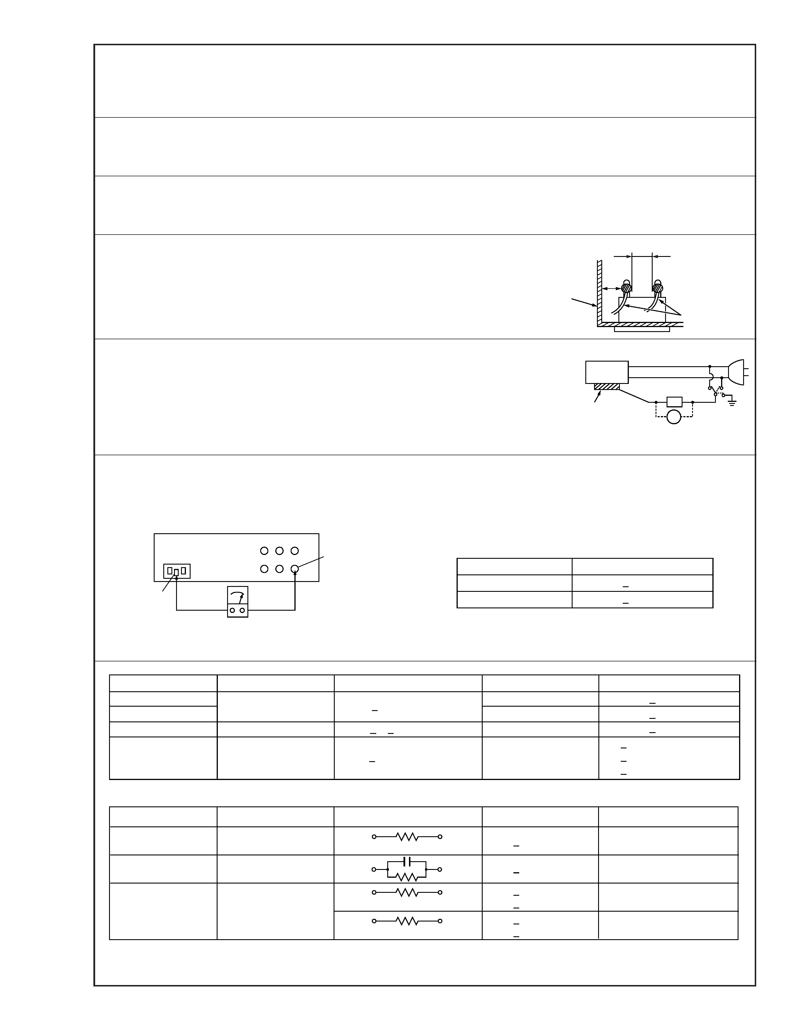
3. Clearance distance
When replacing primary circuit components, confirm specified clearance distance (d), (d') be-
tween soldered terminals, and between terminals and surrounding metallic parts. See table 1
below.
4. Leakage current test
Confirm specified or lower leakage current between earth ground/power cord plug prongs
and externally exposed accessible parts (RF terminals, antenna terminals, video and audio
input and output terminals, microphone jacks, earphone jacks, etc.).
Measuring Method : (Power ON)
Insert load Z between earth ground/power cord plug prongs and externally exposed accessi-
ble parts. Use an AC voltmeter to measure across both terminals of load Z. See figure 9 and
following table 2.
5. Grounding (Class 1 model only)
Confirm specified or lower grounding impedance between earth pin in AC inlet and externally exposed accessible parts (Video in,
Video out, Audio in, Audio out or Fixing screw etc.).
Measuring Method:
Connect milli ohm meter between earth pin in AC inlet and exposed accessible parts. See figure 10 and grounding specifications.
d'
d
Chassis
Power cord,
primary wire
Region
USA & Canada
Europe & Australia
Grounding Impedance (Z)
Z
0.1 ohm
Z
0.5 ohm
AC inlet
Earth pin
Exposed accessible part
Milli ohm meter
Grounding Specifications
Fig. 10
ab
c
V
Externally
exposed
accessible part
Z
Fig. 9
Fig. 8
Clearance Distance (d), (d')
d, d'
3 mm
d, d'
4 mm
d, d'
3.2 mm
1 M
R 12 M/500 V DC
Dielectric Strength
AC 1 kV 1 minute
AC 1.5 kV 1 miute
AC 1 kV 1 minute
AC Line Voltage
100 V
100 to 240 V
110 to 130 V
110 to 130 V
200 to 240 V
Japan
USA & Canada
Europe & Australia
R
10 M
/500 V DC
Region
Insulation Resistance (R)
R
1 M
/500 V DC
AC 3 kV 1 minute
(Class
2)
AC 1.5 kV 1 minute
(Class
1)
d
4 mm
d'
8 mm (Power cord)
d'
6 mm (Primary wire)
Table 1 Specifications for each region
a, b, c
Leakage Current (i)
AC Line Voltage
100 V
110 to 130 V
110 to 130 V
220 to 240 V
Japan
USA & Canada
i
1 mA rms
Exposed accessible parts
Exposed accessible parts
Antenna earth terminals
Other terminals
i
0.5 mA rms
i
0.7 mA peak
i
2 mA dc
i
0.7 mA peak
i
2 mA dc
Europe & Australia
Region
Load Z
1 k
2 k
1.5 k
0.15
µF
50 k
Table 2 Leakage current specifications for each region
Note: These tables are unofficial and for reference only. Be sure to confirm the precise values for your particular country and locality.
2
S40888-01
1-1
SECTION 1
DISASSEMBLY
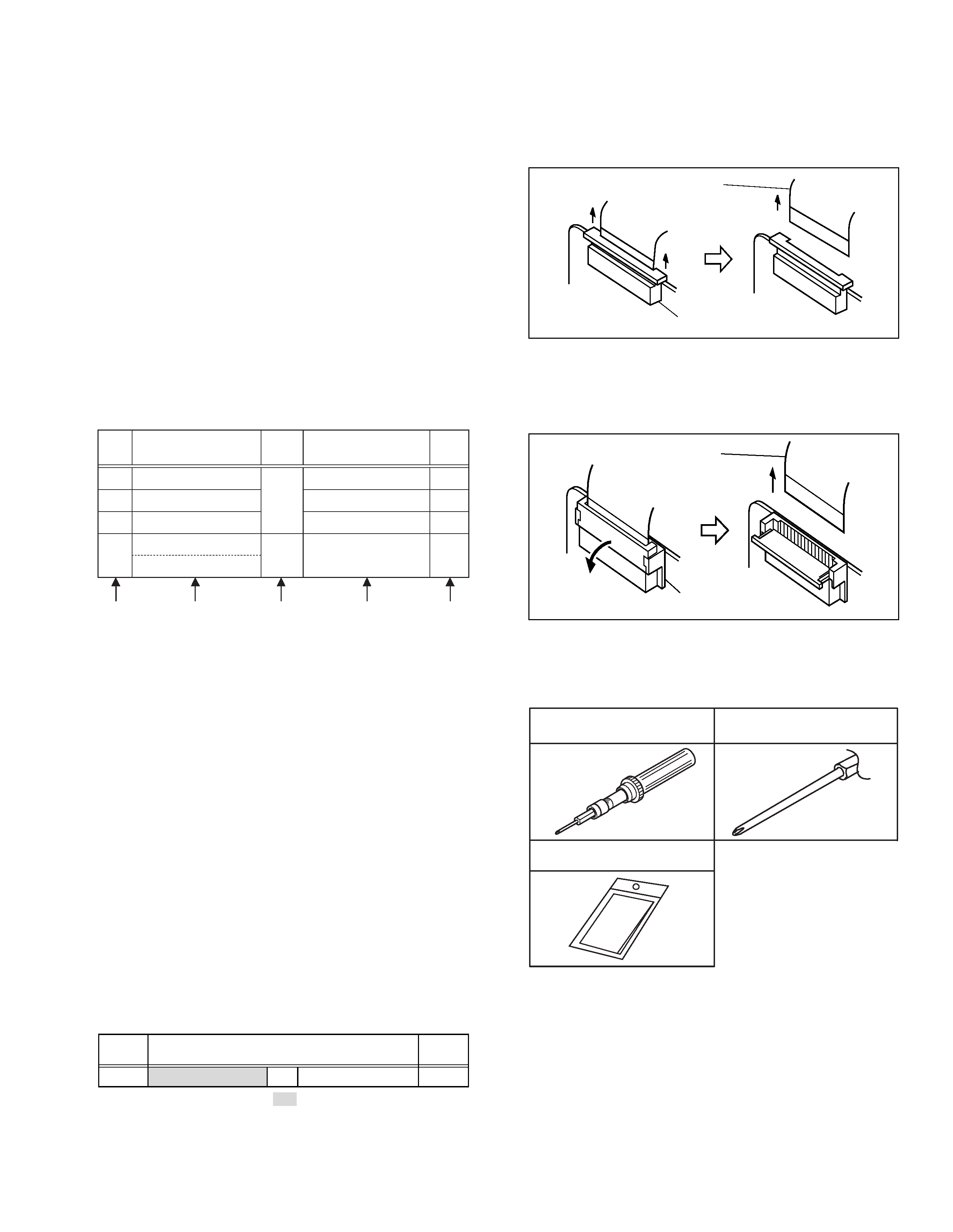
1.1.4 Disconnection of Connectors (Wires)
Pull both ends of the connector in the arrow direction, remove
the lock and disconnect the flat wire.
1.1 BEFORE ASSEMBLY AND DISASSEMBLY
1.1.1
Precautions
1. Be sure to disconnect the power supply unit prior to mount-
ing and soldering of parts.
2. Prior to removing a component part that needs to discon-
nect its connector(s) and its screw(s), first disconnect the
wire(s) from the connector(s), and then remove the screw(s).
3. When connecting/disconnecting wires, pay enough atten-
tion not to damage the connectors.
4. Be careful in removing or handling the part to which some
spacer or shield is attached for reinforcement or insulation.
5. When replacing chip parts (especially IC parts), first remove
the solder completely to prevent peeling of the pattern.
6. Tighten screws properly during the procedures. Unless
specified otherwise, tighten screws at a torque of 0.196N·m
(2.0kgf·cm).
1.1.2 Assembly and disassembly
[Example]
(1) Order of steps in Procedure
When reassembling, preform the step(s) in the reverse or-
der. These numbers are also used as the identification (lo-
cation) No. of parts Figures.
(2) Part to be removed or installed.
(3) Fig. No. showing Procedure or Part Location.
C
= CABINET
D
= CAMERA AND BOARD ASSEMBLY
(4) Identification of part to be removed, unhooked, unlocked,
released, unplugged, unclamped or unsoldered.
P
= Spring
W
= Washer
S
= Screw
*
= Unhook, unlock, release, unplug or unsolder.
2(S3) = 2 Screws (S3)
CN
= Connector
(5) Adjustment information for installation.
1.1.3 Destination of connectors
Two kinds of double-arrows in connection tables respec-
tively show kinds of connector/wires.
: Wire
: Flat wire (FPC, FFC)
[Example]
Remove the parts marked in
.
Fig. 1-1-1
Connector
Flat wire
Fig. 1-1-2
Connector
Flat wire
Extend the locks in the direction of the arrow for unlocking and
then pull out the wire. After removing the wire, immediately
restore the locks to their original positions because the locks
are apt to come off the connector.
LOWER CASE ASSEMBLY
B/W VF ASSEMBLY
TOP OPE UNIT
CASE COVER(S) ASSEMBLY
CASE COVER(M) ASSEMBLY
Fig.C1
Fig.C2
8(S1),CN1a,b,c
3(S2)
CN3,L3a,2(L3b)
(S4),2(L4)
-
-
-
-
[1]
[2]
[3]
[4]
STEP
No.
PART
NOTE
Fig.
No.
POINT
(4)
(5)
(2)
(3)
(1)
CONN.
No.
Pin No.
CONNECTOR
CN1a MAIN
CN27
SPEAKER
2
1.1.5 Tools required for disassembly and assembly
Pull both ends of the connector in the arrow direction, remove
the lock and disconnect the flat wire.
1. Torque driver
Be sure to use to fastening the mechanism and exterior parts
because those parts must strictly be controlled for tighten-
ing torque.
2. Bit
This bit is slightly longer than those set in conventional
torque drivers.
3. Cleaning cloth
Recommended cleaning cloth to wipe down the video
heads, mechanism (tape transport system), optical lens sur-
face.
Torque driver
YTU94088
1
2
Bit
YTU94088-003
3
Cleaning cloth
KSMM-01
Fig. 1-1-3