1-1
UX-F70MD/UX-F72MD
SERVICE MANUAL
MICRO COMPONENT MD SYSTEM
No.21028
Sep. 2001
COPYRIGHT
2001 VICTOR COMPANY OF JAPAN, LTD.
UX-F70MD
UX-F72MD
UX-F70MD/UX-F72MD
Contents
Safety precautions
Preventing static electricity
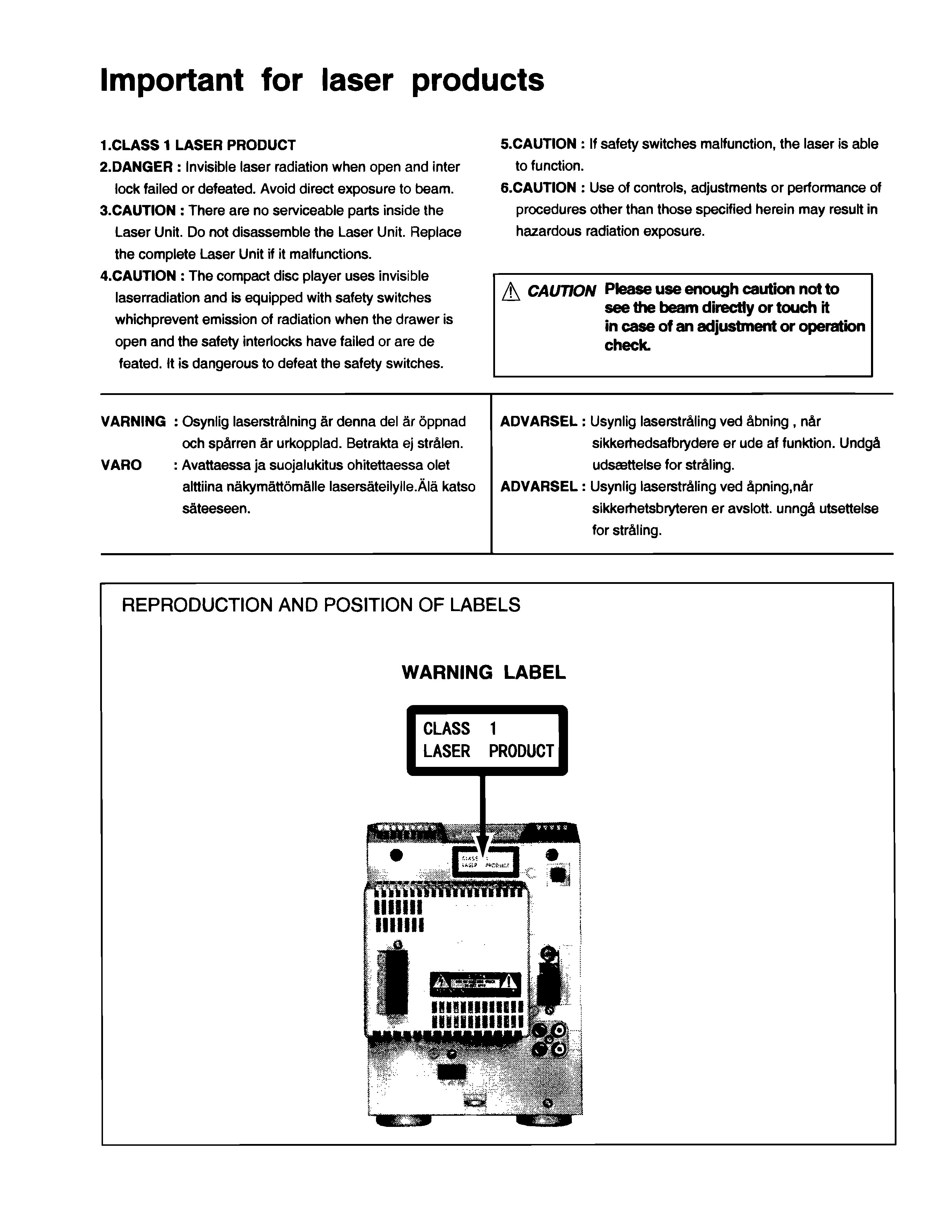
Important for laser products
Disassembly method
Adjustment Method 1
(CD/MD section)
Adjustment Method 2
(Cassette mechanism section)
Flow of functional operation
until TOC read (CD)
Flow of functional operation
until TOC read (MD)
Maintenance of laser pickup
Replacement of laser pickup
Maintenance of MD pickup
Procedures of changing
the MD pickup
Description of major ICs
1-2
1-3
1-5
1-6
1-35
1-38
1-40
1-41
1-42
1-42
1-43
1-43
1-44~71
This service manual is printed on 100% recycled paper.
Area Suffix
UB
UF
Hong Kong
China
COLOR
MD GROUP
MD TITLE
IMPUT/EDIT
CLOCK
/TIMER
FM MODE
DISPLAY
/CHARA
MD TITLE
SEARCH
SOUND
MODE
AHB
PRO
SET
CANCEL
CD
DIMMER
1
2
3
ENTER
FM/AM
/AUX
REV.MODE
REPEAT
TAPE
STANDBY/ON
SLEEP
PLAY MODE
BEEP
VOLUME
MD
4
5
6
7
8
9
10
0
+
10
RM-SUXF70MDU
MARK
STANDBY/ON
COMPACT
DIGITAL AUDIO
MICRO COMPONENT MD SYSTEM UX-F70MD
PHONES
COLOR
MD GROUP
MD TITLE
IMPUT/EDIT
CLOCK
/TIMER
FM MODE
DISPLAY
/CHARA
MD TITLE
SEARCH
SOUND
MODE
AHB
PRO
SET
CANCEL
CD
DIMMER
1
2
3
ENTER
FM/AM
/AUX
REV.MODE
REPEAT
TAPE
STANDBY/ON
SLEEP
PLAY MODE
BEEP
VOLUME
MD
4
5
6
7
8
9
10
0
+
10
RM-SUXF70MDU
MARK
STANDBY/ON
COMPACT
DIGITAL AUDIO
MICRO COMPONENT MD SYSTEM UX-F72MD
PHONES
CA-UXF72MD
CA-UXF70MD
SP-UXF70MD
SP-UXF70MD
SP-UXF72MD
SP-UXF72MD
1-2
UX-F70MD/UX-F72MD
Safety Precautions
1. This design of this product contains special hardware and many circuits and components specially
for safety purposes.
For continued protection, no changes should be made to the original design
unless authorized in writing by the manufacturer.
Replacement parts must be identical to those
used in the original circuits.
Services should be performed by qualified personnel only.
2. Alterations of the design or circuitry of the product should not be made.
Any design alterations of
the product should not be made.
Any design alterations or additions will
void the manufacturer`s
warranty and will further relieve the manufacture of responsibility for personal injury or property
damage resulting therefrom.
3. Many electrical and mechanical parts in the products have special safety-related characteristics.
These characteristics are often not evident from visual inspection nor can the protection afforded
by them necessarily be obtained by using replacement components rated for higher voltage,
wattage, etc.
Replacement parts which have these special safety characteristics are identified in
the Parts List of Service Manual.
Electrical components having such features are identified by
shading on the schematics and by (
) on the Parts List in the Service Manual.
The use of a
substitute replacement which does not have the same safety characteristics as the recommended
replacement parts shown in the Parts List of Service Manual may create shock, fire, or other
hazards.
4. The leads in the products are routed and dressed with ties, clamps, tubings, barriers and the
like to be separated from live parts, high temperature parts, moving parts and/or sharp edges
for the prevention of electric shock and fire hazard.
When service is required, the original lead
routing and dress should be observed, and it should be confirmed that they have been returned
to normal, after re-assembling.
5. Leakage currnet check (Electrical shock hazard testing)
After re-assembling the product, always perform an isolation check on the exposed metal parts
of the product (antenna terminals, knobs, metal cabinet, screw heads, headphone jack, control
shafts, etc.) to be sure the product is safe to operate without danger of electrical shock.
Do not use a line isolation transformer during this check.
Plug the AC line cord directly into the AC outlet.
Using a "Leakage Current Tester", measure
the leakage
current from each exposed metal parts of the cabinet , particularly any exposed
metal part having a return path to the chassis, to a known good earth ground. Any leakage
current must not exceed 0.5mA AC (r.m.s.)
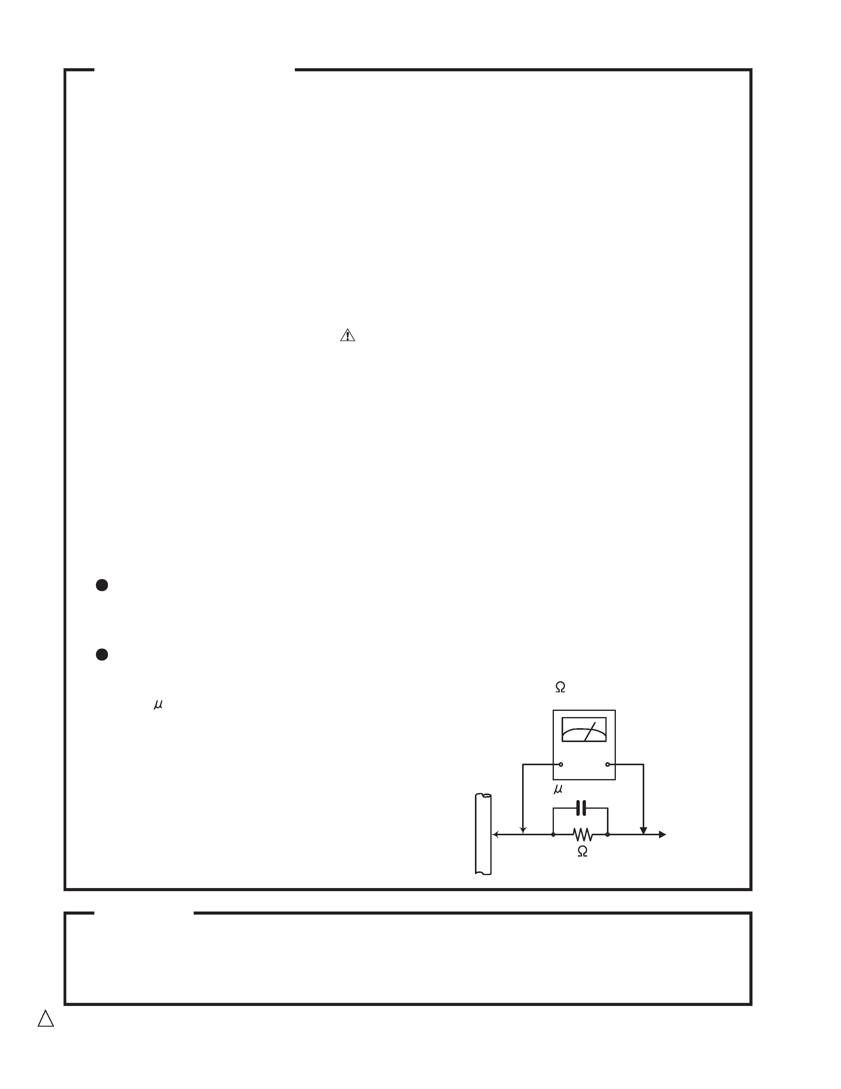
Alternate check method
Plug the AC line cord directly into the AC outlet.
Use an AC voltmeter having, 1,000 ohms
per volt or more sensitivity in the following manner. Connect a 1,500
10W resistor paralleled by
a 0.15 F AC-type capacitor between an exposed
metal part and a known good earth ground.
Measure the AC voltage across the resistor with the
AC voltmeter.
Move the resistor connection to eachexposed metal
part, particularly any exposed metal part having a
return path to the chassis, and meausre the AC
voltage across the resistor. Now, reverse the plug in
the AC outlet and repeat each measurement. voltage
measured Any must not exceed 0.75 V AC (r.m.s.).
This corresponds to 0.5 mA AC (r.m.s.).
Warning
1. This equipment has been designed and manufactured to meet international safety standards.
2. It is the legal responsibility of the repairer to ensure that these safety standards are maintained.
3. Repairs must be made in accordance with the relevant safety standards.
4. It is essential that safety critical components are replaced by approved parts.
5. If mains voltage selector is provided, check setting for local voltage.
Good earth ground
Place this
probe on
each exposed
metal part.
AC VOLTMETER
(Having 1000
ohms/volts,
or more sensitivity)
1500
10W
0.15 F AC TYPE
! CAUTION Burrs formed during molding may be left over on some parts of the chassis. Therefore,
pay attention to such burrs in the case of preforming repair of this system.
1-3
UX-F70MD/UX-F72MD
Preventing static electricity
Electrostatic discharge (ESD), which occurs when static electricity stored in the body, fabric, etc. is discharged,
can destroy the laser diode in the traverse unit (optical pickup). Take care to prevent this when performing repairs.
1.1. Grounding to prevent damage by static electricity
Static electricity in the work area can destroy the optical pickup (laser diode) in devices such as DVD players.
Be careful to use proper grounding in the area where repairs are being performed.
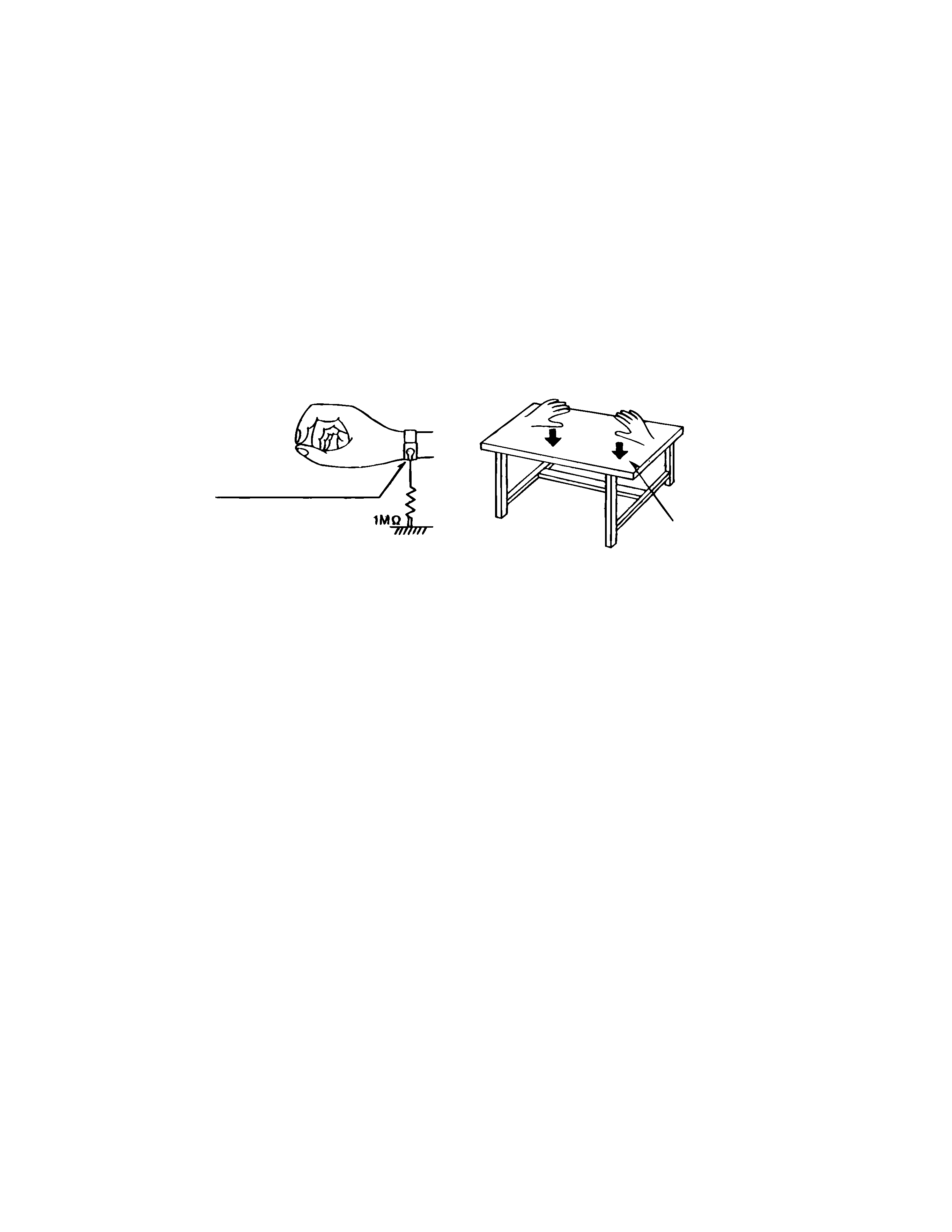
1.1.1. Ground the workbench
1. Ground the workbench by laying conductive material (such as a conductive sheet) or an iron plate over
it before placing the traverse unit (optical pickup) on it.
1.1.2. Ground yourself
1. Use an anti-static wrist strap to release any static electricity built up in your body.
1.1.3. Handling the optical pickup
1. In order to maintain quality during transport and before installation, both sides of the laser diode on the
replacement optical pickup are shorted. After replacement, return the shorted parts to their original condition.
(Refer to the text.)
2. Do not use a tester to check the condition of the laser diode in the optical pickup. The tester's internal power
source can easily destroy the laser diode.
1.2. Handling the traverse unit (optical pickup)
1. Do not subject the traverse unit (optical pickup) to strong shocks, as it is a sensitive, complex unit.
2. Cut off the shorted part of the flexible cable using nippers, etc. after replacing the optical pickup. For specific
details, refer to the replacement procedure in the text. Remove the anti-static pin when replacing the traverse
unit. Be careful not to take too long a time when attaching it to the connector.
3. Handle the flexible cable carefully as it may break when subjected to strong force.
4. It is not possible to adjust the semi-fixed resistor that adjusts the laser power. Do not turn it
Conductive material
(conductive sheet) or iron plate
(caption)
Anti-static wrist strap
1-4
UX-F70MD/UX-F72MD
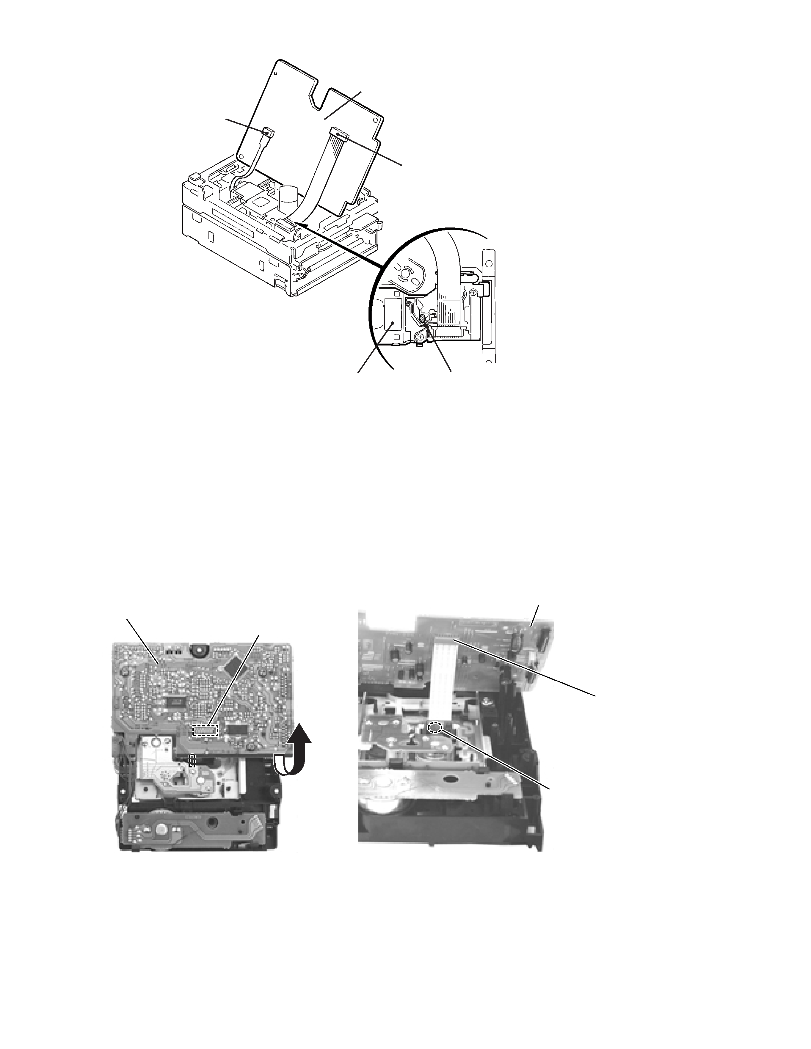
1.3. Cautions on removing the CD traverse unit
* For removing the CD traverse unit in detail, refer to the "Adjustment Method" section of this manual.
1. Before disconnecting the flexible wire from the connector CN601 on the CD SERVO board, solder the part shown in
the figure below.
(Note:If the flexible wire is disconnected from the CN601 without presoldering, it may cause breakdown of the CD
pickup assembly.)
2. When reassembling the CD traverse unit, be sure to remove the solder from the soldered part after reconnecting the
flexible wire to the CN601.
CD SERVO board
CD SERVO board
Soldering part
CN601
CN601
CN321
CN451
Pickup
Soldering part b
MAIN board
CD SERVO board
1-5
UX-F70MD/UX-F72MD