No. 51768
Nov. 2000
TV-20F242
COPYRIGHT © 2000 VICTOR COMPANY OF JAPAN, LTD.
TV-20F242
CONTENTS
SPECIFICATIONS
2
OPERATING INSTRUCTIONS (APPENDED)
SAFETY PRECAUTIONS
3
SPECIFIC SERVICE INSTRUCTIONS
4
SERVICE ADJUSTMENTS
18
GUIDE FOR REPAIRING
30
STANDARD CIRCUIT DIAGRAM (APPENDED)
PARTS LIST
53
SERVICE MANUAL
TV/VCR COMBO

2
TELEVISION
Picture Tube:
20" (measured diagonally)
Tuner Type:
Quartz PLL Frequency Synthesized
Receiving Channels:
VHF
2-13
UHF
14-69
CATV 14-36 (A)-(W)
37-59
(AA)-(WW)
60-85 (AAA)-(ZZZ)
86-94 (86)-(94)
95-99 (A-5)-(A-1)
100-125 (100)-(125)
01 (5A)
Antenna Input:
VHF/UHF In 75 ohms coaxial
Speaker:
3", 8 ohms x 2
Audio Output Power:
1.5 + 1.5 W
VCR
Video System:
VHS ,4 Rotary Heads Helical scanning System
Video Signal:
NTSC Color
Cassette Tape:
VHS
Video Head:
4 Head
Audio Track:
Hi-Fi Sound - 2 Tracks
MONO Sound - 1 Tracks
Tape Speed:
SP:33.35mm/sec
EP:11.12mm/sec
F.FWD/REW Time:
Approx. 1 minutes and 48 seconds (T-120 Cassette)
Speed Search:
SP 3&5 X Normal Speed
EP 9&15 X Normal Speed
GENERAL
Power Source:
AC 120V 60Hz
Power Consumption:
115 Watts
Dimensions:
W 19-3/4" x D 19" x H 20-1/4"
Weight:
55.2 Ibs
Inputs/Outputs:
Video: In (RCA) 1Vp-p 75 ohm
Out (RCA) 1Vp-p 75 ohm
Audio: In (RCA) 300 mV/50K ohm
Out (RCA) 300 mV/1K ohm
Headphone Jack:
3.5mm Stereo mini-jack
Storage Temperature
-20
C ~ 60 C
Operating Temperature
5
C ~ 40 C
Accessories:
Remote Control X 1
Batteries (AA) X 2
Design & specification are subject to change without notice.
SPECIFICATIONS
3
Operating the receiver outside of its cabinet or with its
back removed involves a shock hazard. Work on
these models should only be performed by those who
are thoroughly familiar with precautions necessary
when working on high voltage equipment.
Exercise care when servicing this chassis with power
applied. Many B plus and high voltage RF terminals are
exposed which, if carelessly contacted, can cause
serious shock or result in damage to the chassis.
Maintain interconnecting ground lead connections
between chassis, escutcheon, picture tube dag and
tuner cluster when operating the chassis.
These receivers have a "polarized" AC line cord. The AC
plug is designed to fit into standard AC outlets in one
direction only. The wide blade connects to the "ground
side" and the narrow blade connects to the "hot side" of
the AC line. This assures that the TV receiver is properly
grounded to the house wiring. If an extension cord must
be used, make sure it is of the "polarized" type.
Since the chassis of this receiver is connected to one
side of the AC supply during operation, service should
not be attempted by anyone not familiar with the
precautions necessary when working on these types
of equipment.
When it is necessary to make measurements or tests with
AC power applied to the receiver chassis, an Isolation
Transformer must be used as a safety precaution and to
prevent possible damage to transistors. The Isolation
Transformer should be connected between the TV line
cord plug and the AC power outlet.
Certain HV failures can increase X-ray radiation.
Receivers should not be operated with HV levels
exceeding the specified rating for their chassis type. The
maximum operating HV specified for the chassis used in
these receivers is 32kV 1.0kV at zero beam current with
a line voltage of 120V AC. Higher voltage may also
increase the possibility of failure in the HV supply.
It is important to maintain specified values of all
components in the horizontal and high voltage circuits
and anywhere else in the receiver that could cause a rise
in high voltage, or operating supply voltages. No changes
should be made to the original design of the receiver.
Components shown in the shaded areas on the
schematic diagram and/or identified by ! in the
replacement parts list should be replaced only with
exact factory recommended replacement parts. The
use of unauthorized substitute parts may create
shock, fire, X-ray radiation, or other hazards.
To determine the presence of high voltage, use an
accurate high impedance HV meter connected
between the second anode lead and the CRT dag
grounding device. When servicing the High Voltage
System, remove static charges from it by connecting a
10k ohm resistor in series with an insulated wire (such
as a test probe) between the picture tube dag and 2nd
anode lead (have AC line cord disconnected from AC
supply).
The picture tube used in this receiver employs integral
implosion protection. Replace with a tube of the same
type number for continued safety. Do not lift picture
tube by the neck. Handle the picture tube only when
wearing shatterproof goggles and after discharging the
high voltage completely. Keep others without
shatterproof goggles away.
When removing springs or spring mounted parts from the
tuner, tuner cluster or chassis, shatterproof goggles must
be worn. Keep others without shatterproof goggles away.
Before returning the receiver to the user, perform the
following safety checks:
1.
2.
3.
Inspect all lead dress to make certain that leads are
not pinched or that hardware is not lodged between
the chassis and other metal parts in the receiver.
Replace all protective devices such as nonmetallic
control knobs, insulating fishpapers, cabinet backs,
adjustment and compartment covers or shields,
isolation resistor-capacitor networks, mechanical
insulators, etc.
To be sure that no shock hazard exists, a check for
the presence of leakage current should be made at
each exposed metal part having a return path to the
chassis (antenna, cabinet metal, screw heads,
knobs and/or shafts, escutcheon, etc.) in the
following manner.
Plug the AC line cord directly into a 120V AC receptacle.
(Do not use an Isolation Transformer during these
checks.) All checks must be repeated with the AC line
cord plug connection reversed. (If necessary, a
nonpolarized adapter plug must be used only for the
purpose of completing these checks.)
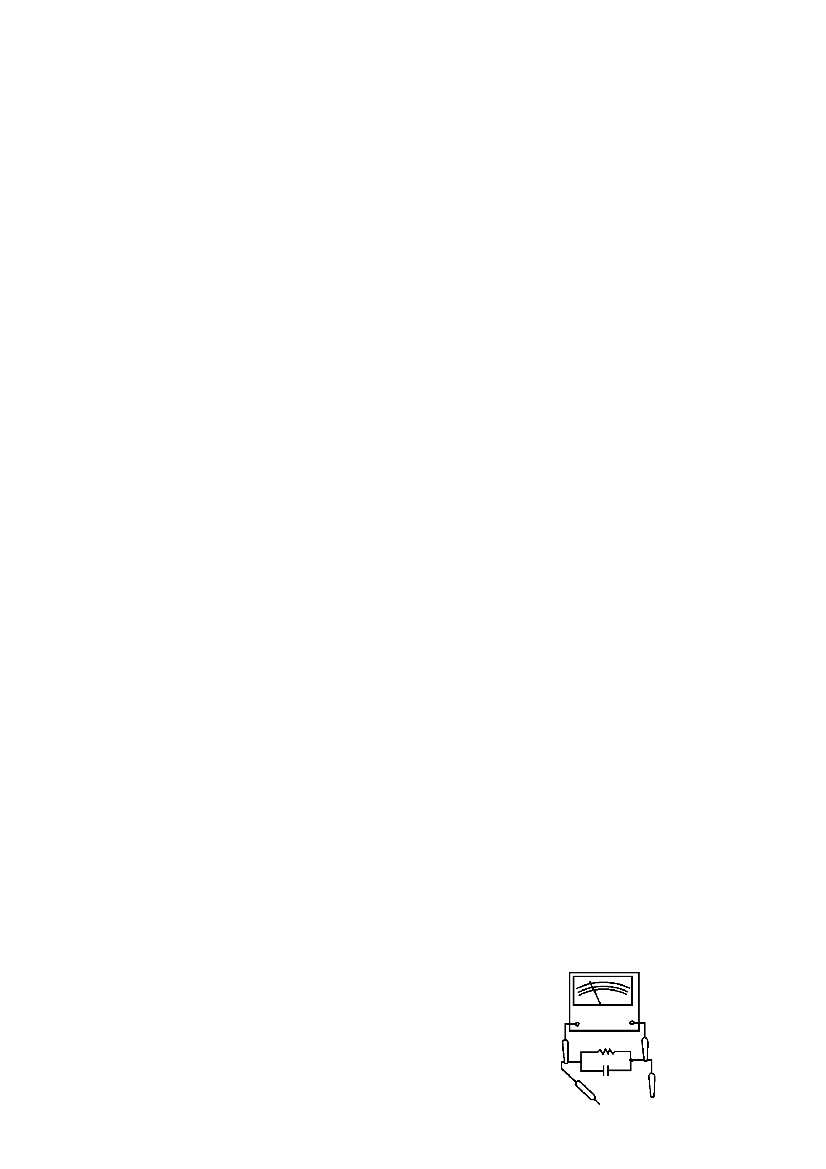
If available, measure current using an accurate leakage
current tester. Any reading of 0.35mA or more is
excessive and indicates a potential shock hazard which
must be corrected before returning the receiver to the
owner.
If a reliable leakage current tester is not available, this
alternate method of measurement should be used.
Using two clip leads, connect a 1500 ohm, 10 watt
resistor paralleled by a 0.15 F capacitor in series with
a known earth ground, such as a water pipe or conduit
and the metal part to be checked. Use a VTVM or
VOM with 1000 ohms per volt, or higher, sensitivity to
measure this AC voltage drop across the resistor. Any
reading of 0.35 volt RMS or more is excessive and
indicates a potential shock hazard which must be
corrected before returning the receiver to the owner.
TO EXPOSED
METAL PARTS
TO KNOWN
EARTH GROUND
AC SCALE
VT VM
1.5K OHMS
10W
15 F
TEST PROBE
SAFETY PRECAUTIONS
4
DISASSEMBLY INSTRUCTIONS
1. REMOVAL OF MECHANICAL PARTS
AND P.C. BOARDS
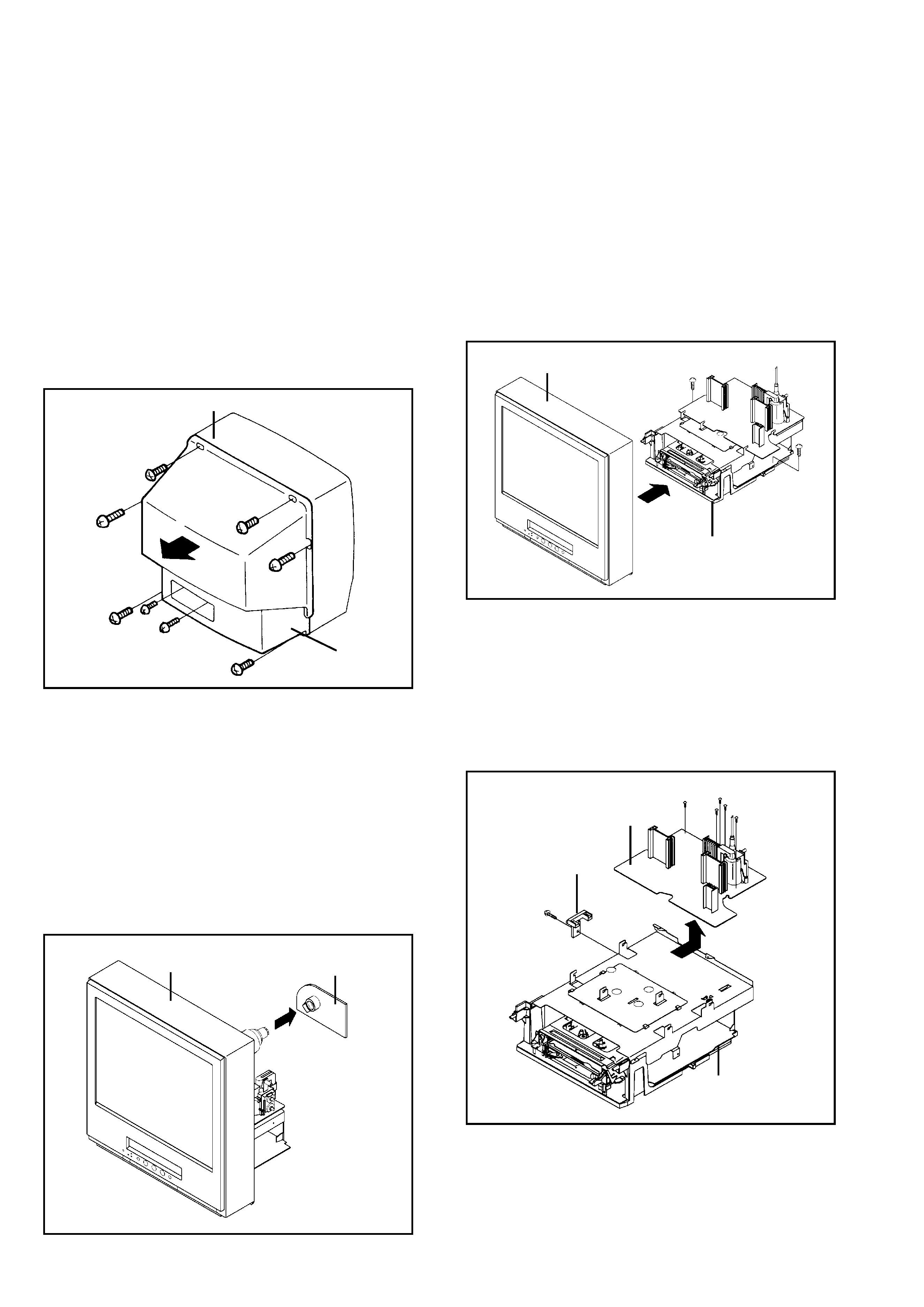
1-1: BACK CABINET (Refer to Fig. 1-1)
1.
2.
3.
4.
Remove the 6 screws 1.
Remove the 2 screws 2 which are used for holding the
Back Cabinet.
Remove the AC cord from the AC cord hook 3.
Remove the Back Cabinet in the direction of arrow.
Fig. 1-1
Front Cabinet
1-2: CRT PCB (Refer to Fig. 1-2)
CAUTION: BEFORE REMOVING THE ANODE CAP,
DISCHARGE ELECTRICITY BECAUSE IT
CONTAINS HIGH VOLTAGE.
BEFORE ATTEMPTING TO REMOVE OR
REPAIR ANY PCB, UNPLUG THE POWER
CORD FROM THE AC SOURCE.
1.
2.
3.
Fig. 1-2
1-3: TV/VCR BLOCK (Refer to Fig. 1-3)
1.
2.
3.
4.
Remove the 2 screws 1.
Disconnect the following connectors:
(CP401, CP502, CP4201 and CP4202).
Unlock the support 2.
Remove the TV/VCR Block in the direction of arrow.
Fig. 1-3
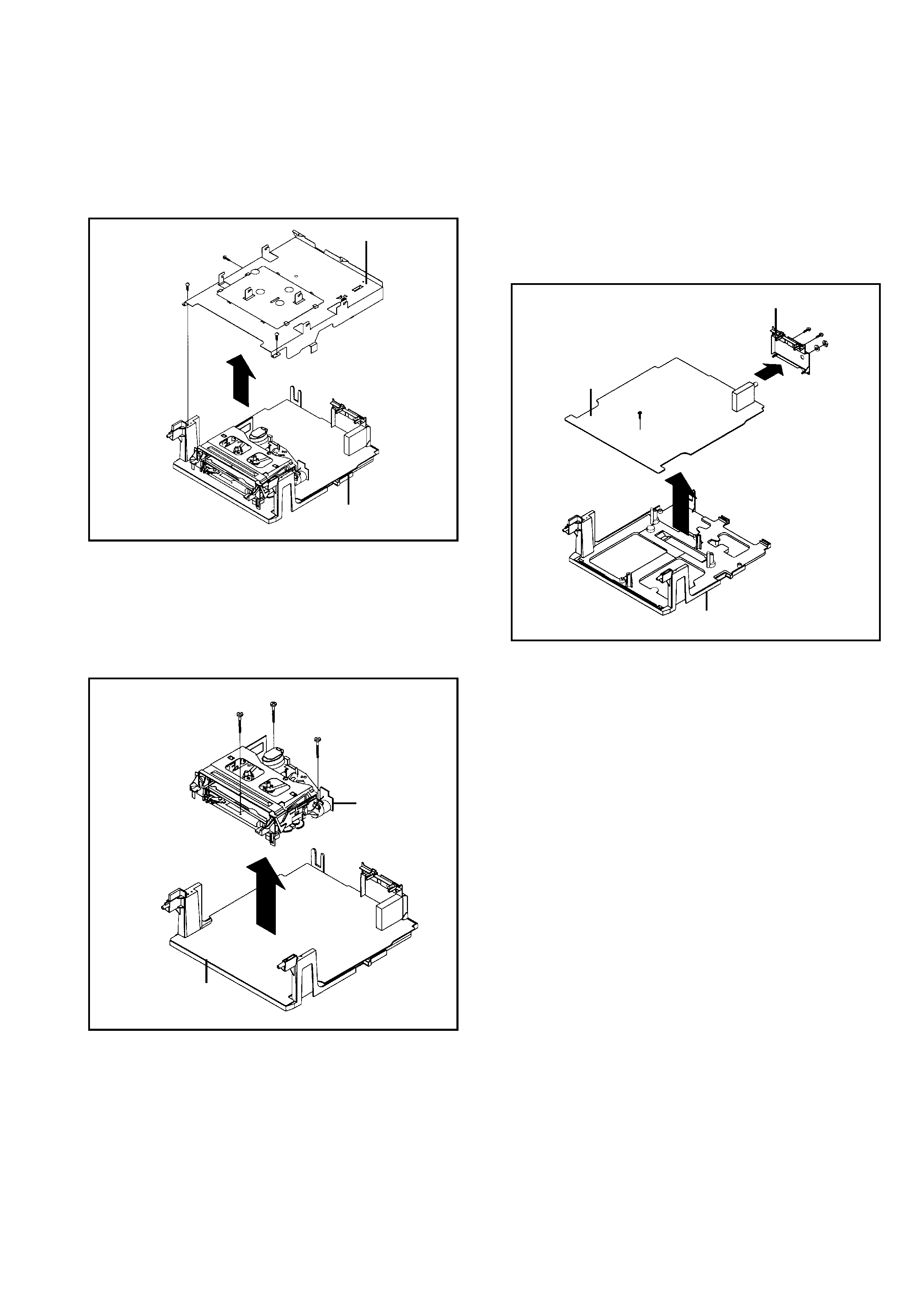
1-4: MAIN PCB (Refer to Fig. 1-4)
1.
2.
3.
4.
5.
6.
Remove the screw 1.
Remove the Main PCB Holder.
Remove the 2 screws 2.
Remove the 3 screws 3.
Disconnect the following connectors:
(CP810 and CP820).
Remove the Main PCB in the direction of arrow.
Remove the Anode Cap.
(Refer to REMOVAL OF ANODE CAP)
Disconnect the following connectors:
(CP802 and CP805).
Remove the CRT PCB in the direction of arrow.
1
1
2
2
1
1
Back Cabinet
1
1
Front Cabinet
CRT PCB
Front Cabinet
1
1
2
UP TO
RELEASE
TV/VCR Block
Main PCB Holder
VCR Block
1
Main PCB
3
2
Fig. 1-4
3
3
3
2
SPECIFIC SERVICE INSTRUCTIONS
5
1-5: DECK SHIELD PLATE (Refer to Fig. 1-5)
1.
2.
3.
1-7: JACK PLATE AND SYSCON PCB (Refer to Fig. 1-7)
1.
2.
3.
4.
5.
6.
7.
Remove the screw 1.
Remove the Syscon PCB in the direction of arrow (A).
Remove the 2 screws 2.
Remove the nut 3.
Remove the washer 4.
Unlock the 2 supports 5.
Remove the Jack Plate in the direction of arrow (B).
Jack Plate
1
Deck Holder
Syscon PCB
(A)
5
5
(B)
4
Fig. 1-7
Remove the 2 screws 1.
Remove the screw 2.
Remove the Deck Shield Plate in the direction of arrow.
2
2
3
1
Deck Shield Plate
Fig. 1-5
1-6: DECK CHASSIS (Refer to Fig. 1-6)
1.
2.
3.
Remove the 3 screws 1.
Disconnect the following connectors:
(CP1004, CP1005, CP1006, CP4001, CP4002 and
CP4003).
Remove the Deck Chassis in the direction of arrow.
1
1
1
Deck Chassis
Syscon PCB
Fig. 1-6
1
VCR Block
2