SERVICE MANUAL
TV-13143
TV-13143W
TV/VCR COMBO
No. 51988
Feb. 2002
COPYRIGHT © 2002 VICTOR COMPANY OF JAPAN, LTD.
TV-13143
TV-13143W
POWER
ONTIMER
RECTIMER
REC
STOP/EJECT
FF
PLAY
REW
VOLUME
CHANNEL
SP/EP
INPUT
PHONES VIDEO-IN-AUDIO
/
REC/ITR
VIDEO CASSETTE RECORDER
PLAY
STOP
REC
PAUSE
FF
REW
TRACKING
AUTO
SLEEP
CALL
INPUT
ENTER
SET
SET +
MENU
ZERO RETURN
RESET
PROGRAM
SP/EP
TIMER
POWER
COUNTER
CANCEL
TV/CAP/TEXT
RETURN
0
8
5
2
7
4
1
9
6
3
MUTING
CH
CH
VOL
VOL
CONTENTS
a SPECIFICATIONS ....................................................................................................................................2
¤ OPERATING INSTRUCTIONS (APPENDED)
a SAFETY PRECAUTIONS ........................................................................................................................3
a SPECIFIC SERVICE INSTRUCTIONS ....................................................................................................5
a SERVICE ADJUSTMENTS ....................................................................................................................21
a GUIDE FOR REPAIRING .......................................................................................................................31
¤ STANDARD CIRCUIT DIAGRAM ........................................................................................................ 2-1
a PARTS LIST ...........................................................................................................................................55

2
No. 51988
TV-13143
TV-13143W
SPECIFICATIONS
TELEVISION
Picture Tube:
13" (measured diagonally)
Tuner Type:
Quartz PLL Frequency Synthesized
Receiving Channels:
VHF
2-13
UHF
14-69
CATV
14-36 (A)-(W)
37-59 (AA)-(WW)
60-85 (AAA)-(ZZZ)
86-94 (86)-(94)
95-99 (A-5)-(A-1)
100-125 (100)-(125)
01 (5A)
Antenna Input:
VHF/UHF In 75 ohms coaxial
Speaker:
1.5" x 2.5", 8 ohms x 1
Audio Output Power:
1.5 W
VCR
Video System:
VHS ,4 Rotary Heads Helical scanning System
Video Signal:
NTSC Color
Cassette Tape:
VHS
Video Head:
4 Head
Audio Track:
1 Track
Tape Speed:
SP:33.35mm/sec
EP:11.12mm/sec
F.FWD/REW Time:
F.FWD: Approx. 4 minutes and 50 seconds
REW:
Approx. 2 minutes and 30 seconds
(T-120 Cassette)
Speed Search:
SP 3&5 X Normal Speed
EP 9&15 X Normal Speed
GENERAL
Power Source:
AC 120V 60Hz
Power Consumption:
65 Watts
Dimensions:
W 14-1/4" x D 14-7/16" x H 15-1/16"
Weight:
24.3 Ibs/11 kg
Inputs:
Video: In (RCA) 1Vp-p 75 ohm
Audio: In (RCA) 300 mV/50K ohm
Headphone Jack:
3.5mm mini-jack
Storage Temperature
-20 °C ~ 60 °C
Operating Temperature
5 °C ~ 40 °C
Accessories:
Remote Control X 1
Batteries (AA) X 2
Design & specification are subject to change without notice.
No. 51988
3
TV-13143
TV-13143W
SAFETY PRECAUTIONS
SERVICING NOTICES ON CHECKING
6. AVOID AN X-RAY
1. KEEP THE NOTICES
As for the places which need special attentions,
they are indicated with the labels or seals on the
cabinet, chassis and parts. Make sure to keep the
indications and notices in the operation manual.
3. USE THE DESIGNATED PARTS
5. TAKE CARE TO DEAL WITH THE
CATHODE-RAY TUBE
In the condition that an explosion-proof cathode-
ray tube is set in this equipment, safety is
secured against implosion. However, when
removing it or serving from backward, it is
dangerous to give a shock. Take enough care to
deal with it.
Safety is secured against an X-ray by consider-
ing about the cathode-ray tube and the high
voltage peripheral circuit, etc.
Therefore, when repairing the high voltage pe-
ripheral circuit, use the designated parts and
make sure not modify the circuit.
Repairing except indicates causes rising of high
voltage, and it emits an X-ray from the cathode-
ray tube.
Please include the following informations when you order parts. (Particularly the VERSION LETTER.)
1. MODEL NUMBER and VERSION LETTER
The MODEL NUMBER can be found on the back of each product and the VERSION LETTER can be
found at the end of the SERIAL NUMBER.
2. PART NO. and DESCRIPTION
You can find it in your SERVICE MANUAL.
HOW TO ORDER PARTS
PERFORM A SAFETY CHECK AFTER
SERVICING
7.
Confirm that the screws, parts and wiring which
were removed in order to service are put in the
original positions, or whether there are the
portions which are deteriorated around the
serviced places serviced or not. Check the
insulation between the antenna terminal or
external metal and the AC cord plug blades.
And be sure the safety of that.
(INSULATION CHECK PROCEDURE)
1.
2.
3.
4.
Unplug the plug from the AC outlet.
Remove the antenna terminal on TV and turn
on the TV.
Insulation resistance between the cord plug
terminals and the eternal exposure metal
[Note 2] should be more than 1M ohm by
using the 500V insulation resistance meter
[Note 1].
If the insulation resistance is less than 1M
ohm, the inspection repair should be
required.
[Note 1]
If you have not the 500V insulation
resistance meter, use a Tester.
[Note 2]
External exposure metal: Antenna terminal
Earphone jack
2. AVOID AN ELECTRIC SHOCK
There is a high voltage part inside. Avoid an
electric shock while the electric current is
flowing.
The parts in this equipment have the specific
characters of incombustibility and withstand
voltage for safety. Therefore, the part which is
replaced should be used the part which has
the same character.
Especially as to the important parts for safety
which is indicated in the circuit diagram or the
table of parts as a
mark, the designated
parts must be used.
4. PUT PARTS AND WIRES IN THE
ORIGINAL POSITION AFTER
ASSEMBLING OR WIRING
There are parts which use the insulation
material such as a tube or tape for safety, or
which are assembled in the condition that
these do not contact with the printed board.
The inside wiring is designed not to get closer
to the pyrogenic parts and high voltage parts.
Therefore, put these parts in the original
positions.
4
No. 51988
TV-13143
TV-13143W
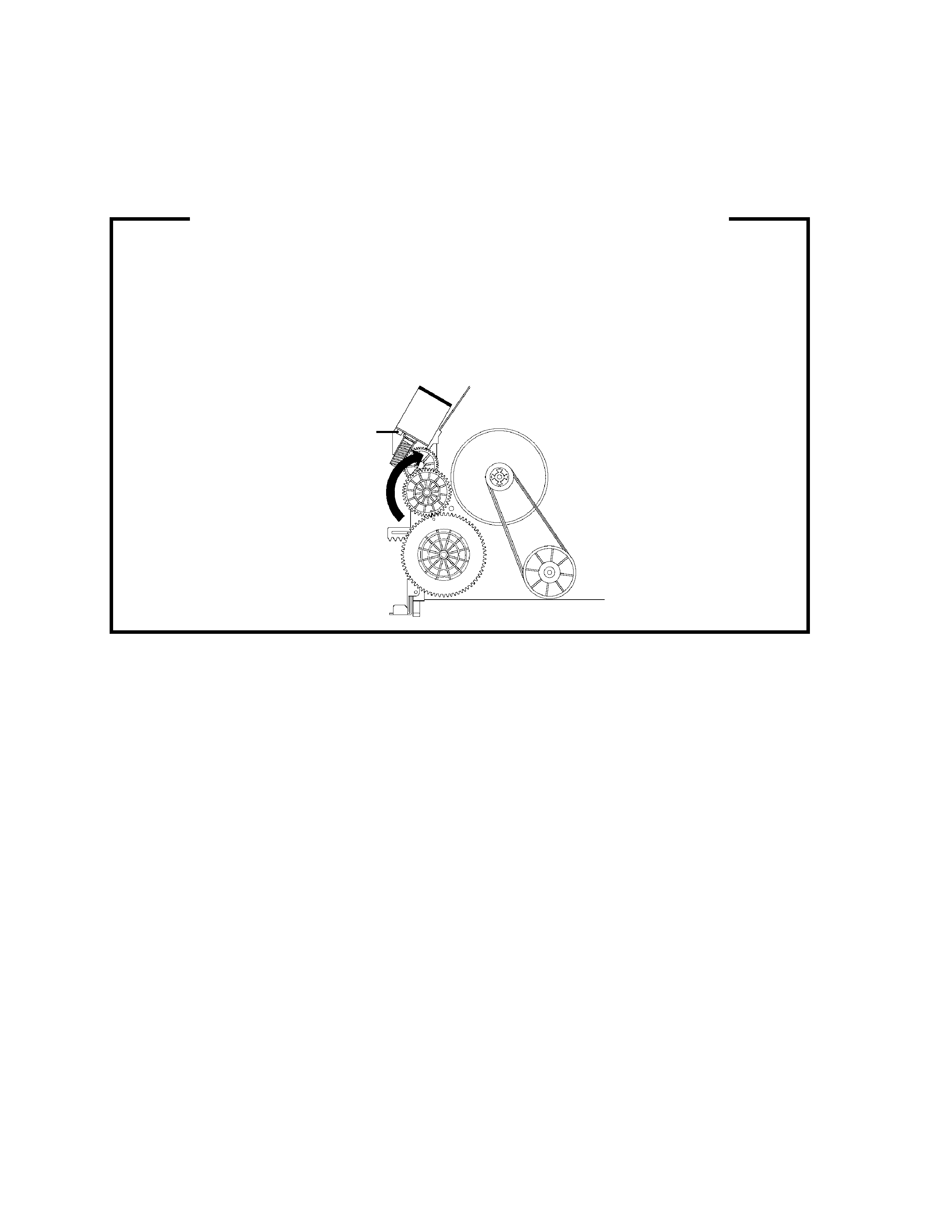
1.
2.
3.
4.
5.
Remove the VCR block from the main unit.
(Refer to item 1 of the DISASSEMBLY INSTRUCTIONS.)
Remove the screw
1 of the Deck Chassis and remove the Loading Motor.
Rotate the Pinch Roller Cam in the direction of the arrow by hand to slacken the Video Tape.
Rotate the Clutch Ass'y either of the directions to wind the Video Tape in the Cassette Case.
Repeat the above step 3~4. Then take out the Video Cassette from the Deck Chassis. Be careful not to
scratch on the tape.
TAPE REMOVAL METHOD AT NO POWER SUPPLY
Pinch Roller Cam
Main Cam
Clutch Ass'y
Main Chassis (Front Side)
Loading Motor
Screw
1
Capstan DD Unit
No. 51988
5
TV-13143
TV-13143W
DISASSEMBLY INSTRUCTIONS
CP4003
1
2
3
(A)
5
5
5
Deck Shield Plate
Deck Chassis
(B)
6
4
Cover Light Plate
Syscon PCB
(C)
Deck Holder
CP4001
CP4002
CP1001
Fig. 1-4
1.
1
1
Front Cabinet
Fig. 1-1
REMOVAL OF MECHANICAL PARTS
AND P.C. BOARDS
1-1: BACK CABINET (Refer to Fig. 1-1)
1.
2.
3.
Remove the 5 screws
1.
Remove the AC cord from the AC cord hook
2.
Remove the Back Cabinet in the direction of arrow.
1-2: CRT PCB (Refer to Fig. 1-2)
1.
2.
3.
Fig. 1-3
1
1
2
1
Back Cabinet
BEFORE REMOVING THE ANODE CAP,
DISCHARGE ELECTRICITY BECAUSE IT
CONTAINS HIGH VOLTAGE.
BEFORE ATTEMPTING TO REMOVE OR
REPAIR ANY PCB, UNPLUG THE POWER
CORD FROM THE AC SOURCE.
CAUTION:
Remove the Anode Cap.
(Refer to REMOVAL OF ANODE CAP)
Disconnect the following connector:
(CP801).
Remove the CRT PCB in the direction of arrow.
Fig. 1-2
Front Cabinet
CRT PCB
CP801
Front Cabinet
1-4:
TV/VCR Block
2
CP502
UP TO
RELEASE
CP401
CP353
CP757
1
1
DECK CHASSIS AND SYSCON PCB
(Refer to Fig. 1-4)
1.
2.
3.
4.
5.
6.
7.
8.
9.
10.
Remove the screw
1.
Remove the screw
2.
Remove the screw
3.
Remove the Deck Shield Plate in direction of arrow (A).
Remove the screw
4 and remove the Cover Light Plate.
Remove the 3 screws
5.
Disconnect the following connectors:
(CP1001, CP4001, CP4002 and CP4003).
Remove the Deck Chassis in the direction of arrow (B).
Remove the screw
6.
Remove the Syscon PCB in the direction of arrow (C).
1-3: TV/VCR BLOCK (Refer to Fig. 1-3)
1.
2.
3.
4.
Remove the 2 screws
1.
Disconnect the following connectors:
(CP401, CP502, CP757 and CP353).
Unlock the support
2.
Remove the TV/VCR Block in the direction of arrow.
SPECIFIC SERVICE INSTRUCTIONS