No. 51810
Mar. 2001
TV-13142
TV-13142W
COPYRIGHT © 2001 VICTOR COMPANY OF JAPAN, LTD.
TV-13142
TV-13142W
CONTENTS
SPECIFICATIONS
2
OPERATING INSTRUCTIONS (APPENDED)
SAFETY PRECAUTIONS
3
SPECIFIC SERVICE INSTRUCTIONS
4
SERVICE ADJUSTMENTS
17
GUIDE FOR REPAIRING
29
STANDARD CIRCUIT DIAGRAM (APPENDED)
PARTS LIST
55
SERVICE MANUAL
TV/VCR COMBO

2
TV-13142
TV-13142W
SPECIFICATIONS
TELEVISION
Picture Tube:
13" (measured diagonally)
Tuner Type:
Quartz PLL Frequency Synthesized
Receiving Channels:
VHF
2-13
UHF
14-69
CATV 14-36 (A)-(W)
37-59
(AA)-(WW)
60-85 (AAA)-(ZZZ)
86-94 (86)-(94)
95-99 (A-5)-(A-1)
100-125 (100)-(125)
01 (5A)
Antenna Input:
VHF/UHF In 75 ohms coaxial
Speaker:
1.5"
2.5", 8 ohms x 1
Audio Output Power:
1.5 W
VCR
Video System:
VHS ,4 Rotary Heads Helical scanning System
Video Signal:
NTSC Color
Cassette Tape:
VHS
Video Head:
4 Head
Audio Track:
Hi-Fi Sound - 2 Tracks
MONO Sound - 1 Tracks
Tape Speed:
SP:33.35mm/sec
EP:11.12mm/sec
F.FWD/REW Time:
Approx. 1 minutes and 48 seconds (T-120 Cassette)
Speed Search:
SP 3&5 X Normal Speed
EP 9&15 X Normal Speed
GENERAL
Power Source:
AC 120V 60Hz
Power Consumption:
65 Watts
Dimensions:
W 19-3/4" x D 19" x H 20-1/4"
Weight:
55.2 Ibs
Inputs/Outputs:
Video: In (RCA) 1Vp-p 75 ohm
Out (RCA) 1Vp-p 75 ohm
Audio: In (RCA) 300 mV/50K ohm
Out (RCA) 300 mV/1K ohm
Headphone Jack:
3.5mm Stereo mini-jack
Storage Temperature
-20 ºC ~ 60 ºC
Operating Temperature
5 ºC ~ 40 ºC
Accessories:
Remote Control X 1
Batteries (AA) X 2
Design & specification are subject to change without notice.
3
TV-13142
TV-13142W
SERVICING NOTICES ON CHECKING
6. AVOID AN X-RAY
1. KEEP THE NOTICES
As for the places which need special attentions,
they are indicated with the labels or seals on the
cabinet, chassis and parts. Make sure to keep the
indications and notices in the operation manual.
3. USE THE DESIGNATED PARTS
5. TAKE CARE TO DEAL WITH THE
CATHODE-RAY TUBE
In the condition that an explosion-proof cathode-
ray tube is set in this equipment, safety is
secured against implosion. However, when
removing it or serving from backward, it is
dangerous to give a shock. Take enough care to
deal with it.
Safety is secured against an X-ray by consider-
ing about the cathode-ray tube and the high
voltage peripheral circuit, etc.
Therefore, when repairing the high voltage pe-
ripheral circuit, use the designated parts and
make sure not modify the circuit.
Repairing except indicates causes rising of high
voltage, and it emits an X-ray from the cathode-
ray tube.
Please include the following informations when you order parts. (Particularly the VERSION LETTER.)
1. MODEL NUMBER and VERSION LETTER
The MODEL NUMBER can be found on the back of each product and the VERSION LETTER can be
found at the end of the SERIAL NUMBER.
2. PART NO. and DESCRIPTION
You can find it in your SERVICE MANUAL.
HOW TO ORDER PARTS
PERFORM A SAFETY CHECK AFTER
SERVICING
7.
Confirm that the screws, parts and wiring which
were removed in order to service are put in the
original positions, or whether there are the
portions which are deteriorated around the
serviced places serviced or not. Check the
insulation between the antenna terminal or
external metal and the AC cord plug blades.
And be sure the safety of that.
(INSULATION CHECK PROCEDURE)
1.
2.
3.
4.
Unplug the plug from the AC outlet.
Remove the antenna terminal on TV and turn
on the TV.
Insulation resistance between the cord plug
terminals and the eternal exposure metal
[Note 2] should be more than 1M ohm by
using the 500V insulation resistance meter
[Note 1].
If the insulation resistance is less than 1M
ohm, the inspection repair should be
required.
[Note 1]
If you have not the 500V insulation
resistance meter, use a Tester.
[Note 2]
External exposure metal: Antenna terminal
Earphone jack
2. AVOID AN ELECTRIC SHOCK
There is a high voltage part inside. Avoid an
electric shock while the electric current is
flowing.
The parts in this equipment have the specific
characters of incombustibility and withstand
voltage for safety. Therefore, the part which is
replaced should be used the part which has
the same character.
Especially as to the important parts for safety
which is indicated in the circuit diagram or the
table of parts as a
mark, the designated
parts must be used.
4. PUT PARTS AND WIRES IN THE
ORIGINAL POSITION AFTER
ASSEMBLING OR WIRING
There are parts which use the insulation
material such as a tube or tape for safety, or
which are assembled in the condition that
these do not contact with the printed board.
The inside wiring is designed not to get closer
to the pyrogenic parts and high voltage parts.
Therefore, put these parts in the original
positions.
SAFTY PRECAUITONS
4
TV-13142
TV-13142W
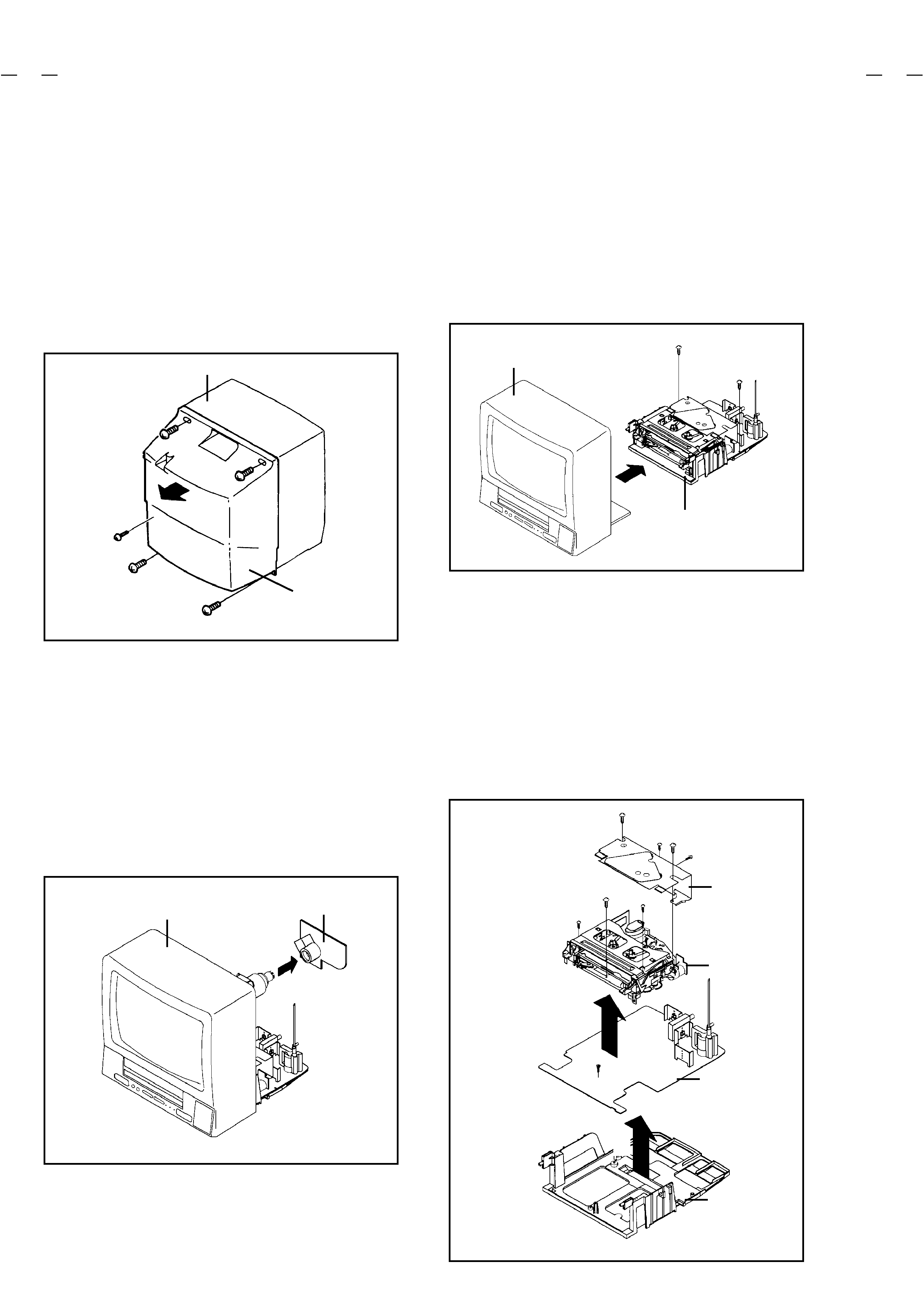
DISASSEMBLY INSTRUCTIONS
1. REMOVAL OF MECHANICAL PARTS
AND P.C. BOARDS
1-1: BACK CABINET (Refer to Fig. 1-1)
1.
2.
3.
4.
1-3: TV/VCR BLOCK (Refer to Fig. 1-3)
Fig. 1-3
Remove the 4 screws
1.
Remove the screw
2.
Remove the AC cord from the AC cord hook
3.
Remove the Back Cabinet in the direction of arrow.
Fig. 1-1
Front Cabinet
Back Cabinet
1
1
1
3
2
1
1-2: CRT PCB (Refer to Fig. 1-2)
CAUTION: BEFORE REMOVING THE ANODE CAP,
DISCHARGE ELECTRICITY BECAUSE IT
CONTAINS HIGH VOLTAGE.
BEFORE ATTEMPTING TO REMOVE OR
REPAIR ANY PCB, UNPLUG THE POWER
CORD FROM THE AC SOURCE.
1.
2.
3.
Front Cabinet
CRT PCB
Fig. 1-2
1.
2.
3.
4.
Remove the 2 screws
1.
Disconnect the following connectors:
(CP757, CP353, CP401 and CP502).
Unlock the support
2.
Remove the TV/VCR Block in the direction of arrow.
Remove the Anode Cap.
(Refer to REMOVAL OF ANODE CAP)
Disconnect the following connectors:
(CP801 and CP851B).
Remove the CRT PCB in the direction of arrow.
1
1
2
UP TO
RELEASE
TV/VCR Block
1-4: DECK CHASSIS AND SYSCON PCB
(Refer to Fig. 1-4)
1.
2.
3.
4.
5.
6.
7.
Remove the 3 screws
1.
Remove the 3 screws
2.
Remove the screw
3.
Disconnect the following connectors:
(CP1004, CP1005, CP1006, CP4001, CP4002 and
CP4003).
Remove the Deck Chassis and Deck Shield Plate in the
direction of arrow (A).
Remove the screw
4.
Remove the Syscon PCB in the direction of arrow (B).
Front Cabinet
1
1
2
2
2
4
Deck Chassis
Deck Shield Plate
(A)
Syscon PCB
Deck Holder
Fig. 1-4
(B)
1
3
SPECIFIC SERVICE INSTRUCTIONS
5
TV-13142
TV-13142W
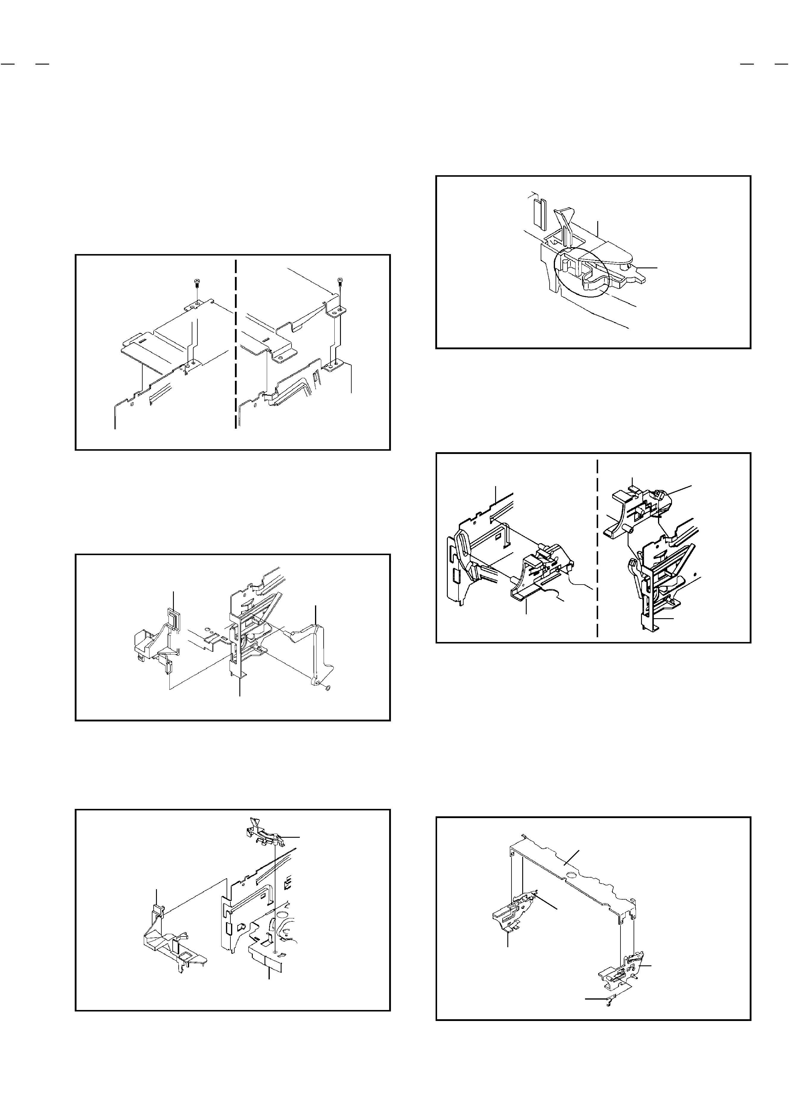
DISASSEMBLY INSTRUCTIONS
NOTE
When you install the Tape Guide L, install as shown in the
circle of Fig. 2-3-B. (Refer to Fig. 2-3-B)
REC Lever
Tape Guide L
· The REC Lever is not installed on the Video Cassette Player.
Fig. 2-3-B
2-4: CASSETTE HOLDER ASS'Y (Refer to Fig. 2-4)
2. REMOVAL OF DECK PARTS
2-1: TOP BRACKET (Refer to Fig. 2-1)
Remove the 2 screws
1.
Slide the 2 supports
2 and remove the Top Bracket.
1.
2.
NOTE
When you install the Top Bracket, install the screw (1)
first, then install the screw (2).
1
(2)
Top Bracket
Top Bracket
Main Chassis
Main Chassis
2
1
(1)
2
Fig. 2-1
· Screw Torque: 5
± 0.5kgf·cm
2-2: FLAP LEVER/TAPE GUIDE R (Refer to Fig. 2-2)
Move the Cassette Holder Ass'y to the back side.
Remove the Polyslider Washer
1.
Remove the Flap Lever.
Unlock the 3 supports
2 and remove the Tape Guide R.
1.
2.
3.
4.
Fig. 2-2
2-3: TAPE GUIDE L (Refer to Fig. 2-3-A)
Move the Cassette Holder Ass'y to the back side.
Unlock the 2 supports
1 and remove the Tape Guide L.
Remove the REC Lever. (Recorder only)
1.
2.
3.
1
Main Chassis
Tape Guide L
REC Lever
Fig. 2-3-A
· The REC Lever is not installed on the Video Cassette Player.
1
1
2
2
2
Tape Guide R
Flap Lever
Main Chassis
Move the Cassette Holder Ass'y to the front side so that
the Link Ass'y doesn't slip out.
Push the Locker R to remove the Cassette Side R.
Remove the Cassette Side L.
1.
2.
3.
Main Chassis
Main Chassis
Cassette Side L
Cassette Side R
Locker R
Fig. 2-4
2-5: CASSETTE SIDE L/R (Refer to Fig. 2-5)
Unlock the 4 supports
1 and then remove the Cassette
Side L/R.
Remove the Cassette Earth Spring.
1.
2.
NOTE
1.
2.
When you install the Cassette Side R, be sure to move
the Locker R after installing.
After the installation of the Cassette Holder, then install
the Cassette Earth Spring.
Cassette Side L
Cassette Side R
1
1
1
Locker R
1
Cassette Holder
Fig. 2-5
Cassette Earth Spring