INSTRUCTIONS
TM-H140PN
COLOUR VIDEO MONITOR
TM-H140PN
PHASE
CHROMA
BRIGHT
CONTRAST
MENU
INPUT SELECT
VOLUME/SELECT
+
B
A
POWER
ON
OFF
UNDER
SCAN
LCT1370-001A-H
0203-MK-MW-MT
© 2003 VICTOR COMPANY OF JAPAN, LIMITED
EN_LCT1370-001A-H.p65
03.2.21, 10:15 AM
1
SAFETY PRECAUTIONS
In order to prevent any fatal accidents caused by misoperation
or mishandling the monitor, be fully aware of all the following
precautions.
WARNINGS
To prevent fire or shock hazard, do not expose this
monitor to rain or moisture. Dangerous high voltages
are present inside the unit. Do not remove the back
cover of the cabinet. When servicing the monitor,
contrast qualified service personnel. Never try to
service it yourself.
WARNING : THIS APPARATUS MUST
BE EARTHED.
PRECAUTIONS
Use only the power source specified on the unit.
When not using this unit for a long period of time, or when
cleaning it, be sure to disconnect the power plug from the
AC outlet.
Do not allow anything to rest on the power cord. And do not
place this unit where people will tread on the cord. Do not
overload wall outlets or power cords as this can result in a
fire or electric shock.
Avoid using this unit under the following conditions:
in extremely hot, cold or humid places,
in dusty places,
near appliances generating strong magnetic fields,
in places subject to direct sunlight,
in badly ventilated places,
in automobiles with doors closed.
Do not cover the ventilation slots while in operation as this
could obstruct the required ventilation flow.
When dust accumulates on the screen surface, clean it with
a soft cloth.
SCREEN BURN
It is not recommended to keep a certain still image displayed on screen for a long time as well as displaying extremely bright
images on screen. This may cause a burning (sticking) phenomenon on the screen of cathode-ray tube. This problem does
not occur as far as displaying normal video playback motion images.
Machine Noise Information Ordinance 3. GSGV,
January 18, 1991: The sound pressure level at the
operator position is equal or less than 70 dB(A)
according to ISO 7779.
Improper operations, in particular alternation of high
voltage or changing the type of tube may result in x-ray
emission of considerable dose. A unit altered in such a
way no longer meets the standards of certification, and
must therefore no longer be operated.
Unplug this unit from the AC outlet and refer servicing to
qualified service personnel under the following conditions:
when the power cord is frayed or the plug is damaged,
if liquid has been spilled into the unit,
if the unit has been dropped or the cabinet has been
damaged,
when the unit exhibits a distinct change in performance.
Do not attempt to service this unit yourself as opening or
removing covers may expose you to dangerous voltage or
other hazards. Always refer servicing to qualified service
personnel.
When replacement parts are required, have the service
personnel verify in writing that the replacement parts he/
she uses have the same safety characteristics as the
original parts. Use of manufacture's specified replacement
parts can prevent fire, shock, or other hazards.
Upon completion of any servicing or repair work to this unit,
please ask the service personnel to perform the safety
check described in the manufacturer's service literature.
When this unit reaches the end of its useful life, improper
disposal could result in a picture tube implosion. Ask
qualified service personnel to dispose of this unit.
Thank you for purchasing this JVC colour video monitor. Before using it, read and follow
all instructions carefully to take full advantage of the monitor's capabilities.
2
EN_LCT1370-001A-H.p65
03.2.21, 10:15 AM
2

3
CONTENTS
SAFETY PRECAUTIONS ................................................................................. 2
CONTROLS AND FEATURES ......................................................................... 4
HOW TO HANDLE BASIC OPERATIONS ........................................................ 7
HOW TO USE THE MENU FUNCTIONS........................................................... 8
HOW TO INITIALIZE THE SETTING ............................................................... 11
BASIC CONNECTION EXAMPLE .................................................................. 12
TROUBLESHOOTING .................................................................................... 14
SPECIFICATIONS .......................................................................................... 15
EN_LCT1370-001A-H.p65
03.2.21, 10:15 AM
3
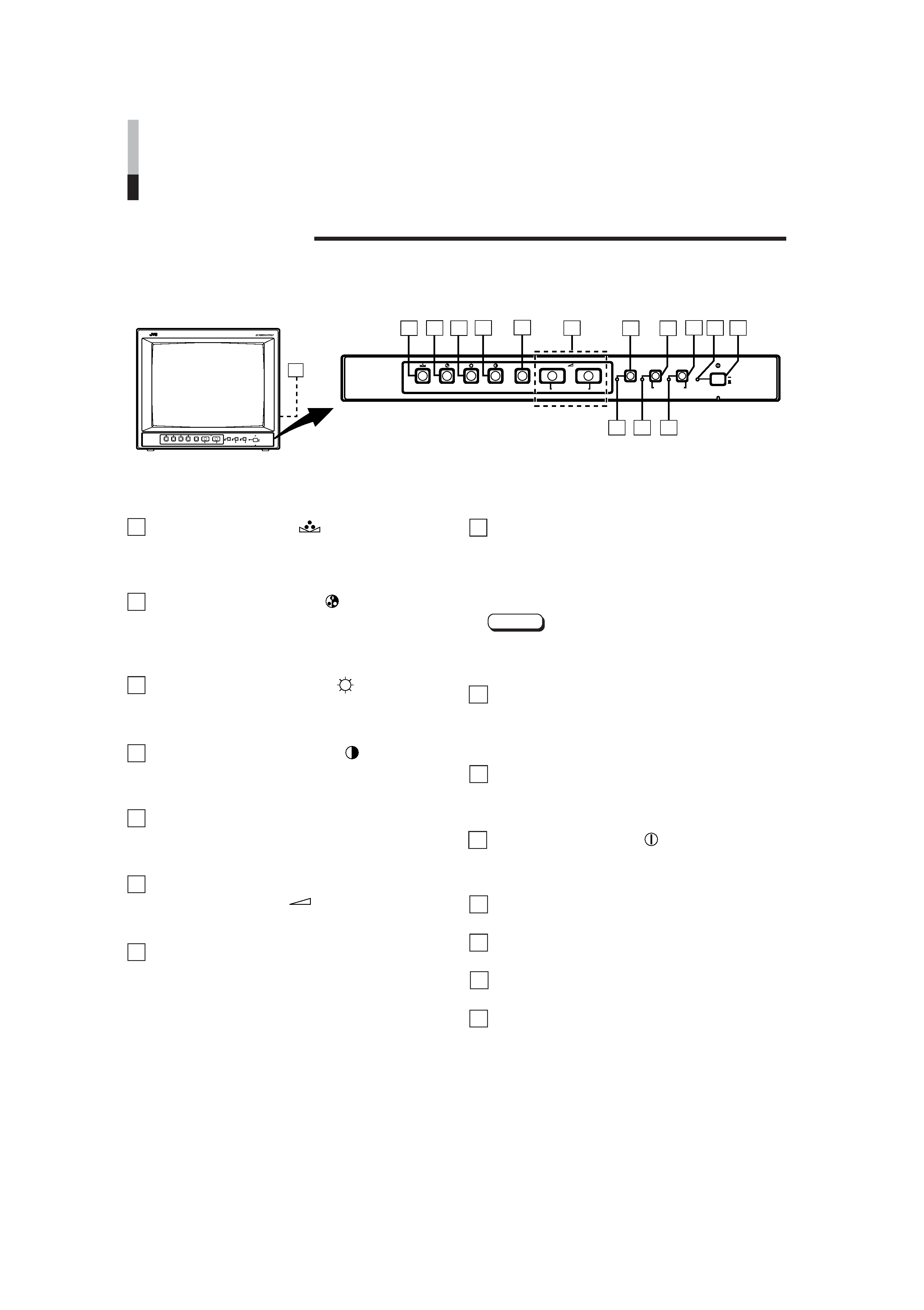
Phase button [PHASE
]
Press this button to set the picture hue adjustment mode.
Adjust the value with the VOLUME/SELECT buttons.
Also used as a control button in the menu function mode.
Chroma button [CHROMA
]
Press this button to set the picture colour density
adjustment mode. Adjust the value with the VOLUME/
SELECT buttons. Also used as a control button in the
menu function mode.
Brightness button [BRIGHT
]
Press this button to adjust picture brightness. Adjust the
value with the VOLUME/SELECT buttons. Also used as a
control button in the menu function mode.
Contrast button [CONTRAST
]
Press this button to adjust picture contrast. Adjust the
value with the VOLUME/SELECT buttons. Also used as a
control button in the menu function mode.
Menu button [MENU]
Displays and disappears the <MENU> screen.
Pressing the PHASE button with the Menu button
depressed will display the <SET-UP MENU> screen.
Volume/Select buttons
[VOLUME/SELECT
+]
Adjusts the speaker volume. Also used as a control
button in the menu function mode.
Under Scan button [UNDER SCAN]
Reduces the screen size to display the whole screen.
Press the button again to quit Under Scan.
CONTROLS AND FEATURES
FRONT VIEW
<Front Panel>
15
TM-H140PN
PHASE
CHROMA
BRIGHT
CONTRAST
MENU
INPUT SELECT
VOLUME/SELECT
+
B
A
POWER
ON
OFF
UNDER
SCAN
1
3
5
6
7
8
9 10
12 13 14
11
2
4
TM-H140PN
PHASE
CHROMA
BRIGHT
CONTRAST
MENU
INPUT SELECT
VOLUME/SELECT
+
B
A
POWER
ON
OFF
UNDER
SCAN
Input B (VIDEO / Y/C) button
[INPUT SELECT B]
Selects the video signal input to the VIDEO B terminal
and the audio signal input to the AUDIO B terminal on
the rear panel. When selected, the input B (VIDEO / Y/C)
indicator # lights.
Note:
* The VIDEO B terminals include a video terminal (BNC
connector) and a Y/C terminal (mini-DIN 4-pin
connector). The Y/C (S-video) terminal is given priority.
Input A (VIDEO) button [INPUT SELECT A]
Selects the video signal input to the VIDEO A terminal
and the audio signal input to the AUDIO A terminal on the
rear panel. When selected, the input A (VIDEO) indicator
$ lights.
Power indicator
Lights in green when the power is ON.
Lit
: When the power is on.
Unlit : When the power is off.
Power switch [POWER
]
Press this switch to turn the power on or off.
g
ON : Power is turned on.
G
OFF : Power is turned off.
UNDER SCAN indicator
Lights in green when UNDER SCAN is selected.
Input B (VIDEO / Y/C) indicator
Lights in green when Input B (VIDEO / Y/C) is selected.
Input A (VIDEO) indicator
Lights in green when Input A (VIDEO) is selected.
Speaker
A built-in speaker is located inside the right side panel
when the monitor is viewed from the front.
1
2
3
4
5
6
7
8
9
10
11
12
13
14
15
4
EN_LCT1370-001A-H.p65
03.2.21, 10:15 AM
4
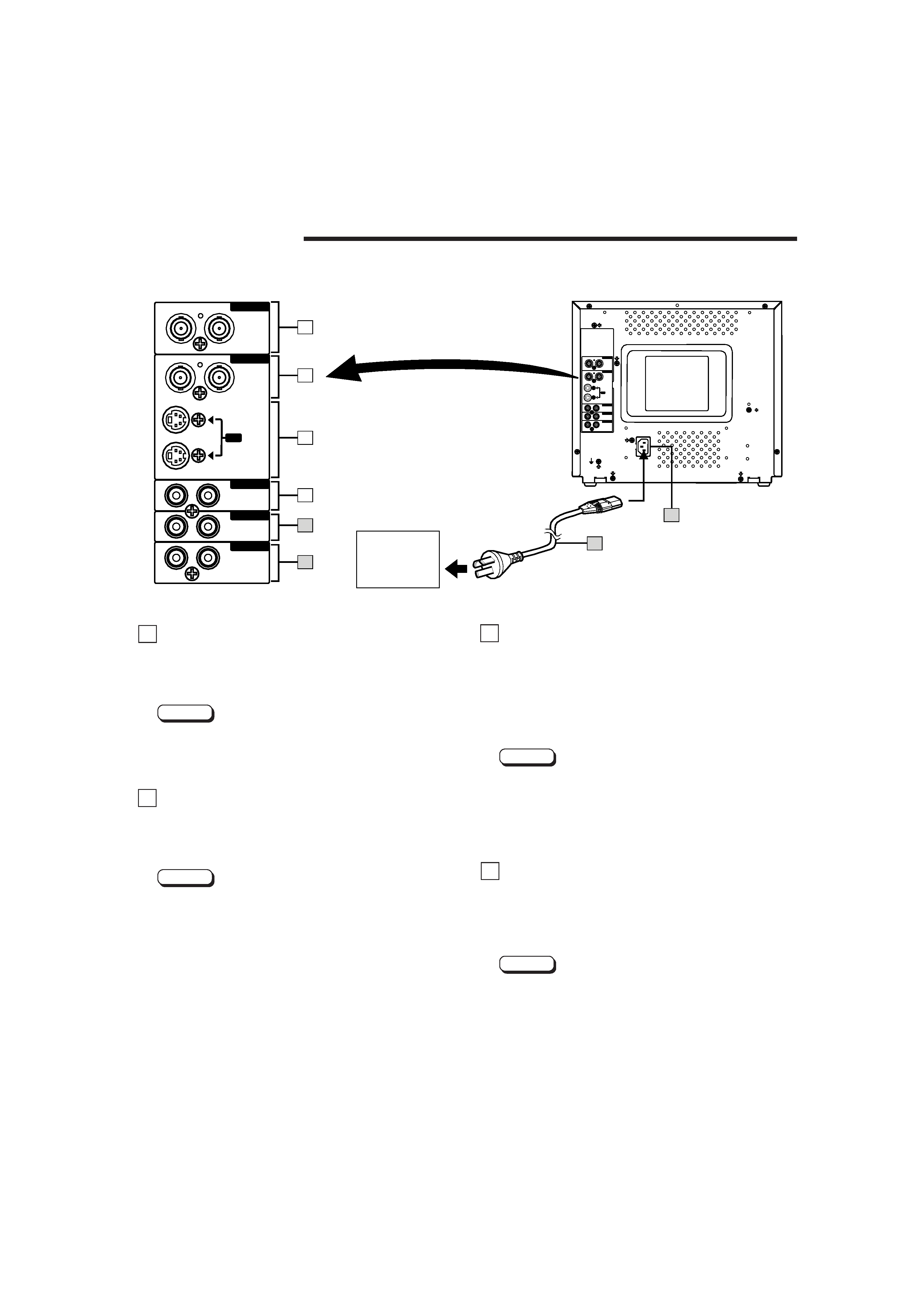
Video A terminals [VIDEO A IN/OUT]
Video signal input (IN) and output (OUT) terminals.
The output terminal is bridge-connected.
IN
: Video signal input terminal
OUT : Bridge-connected video signal output terminal
Notes:
* For corresponding audio signals, use the AUDIO A
terminals (.
* Also refer to BASIC CONNECTION EXAMPLE
on page 12.
Video B terminals [VIDEO B IN/OUT]
Video signal input (IN) and output (OUT) terminals.
The output terminal is bridge-connected.
IN
: Video signal input terminal
OUT : Bridge-connected video signal output terminal
Notes:
* For corresponding audio signals, use the AUDIO B
terminals ).
* When both VIDEO B terminals are connected (input) at
the same time, the Y/C terminal is given priority.
* Also refer to BASIC CONNECTION EXAMPLE on
page 12.
REAR VIEW
<Rear Panel>
Video B (Y/C) terminals
[VIDEO B Y/C IN/OUT]
Y/C (S-Video) signal input (IN) and output (OUT)
terminals.
The output terminal is bridge-connected.
IN
: Y/C-separated (S-video) signal input terminal
OUT : Bridge-connected Y/C-separated (S-video) signal
output terminal
Notes:
* For corresponding audio signals, use the AUDIO B
terminals ).
* When both VIDEO B terminals are connected (input) at
the same time, the Y/C terminal is given priority.
* Also refer to BASIC CONNECTION EXAMPLE on
page 12.
Audio A terminals [AUDIO A IN/OUT]
Input (IN) and output (OUT) terminals for the audio signal
corresponding to the VIDEO A terminals ^.
The output terminal is bridge-connected.
IN
: Audio signal input terminal
OUT : Bridge-connected audio signal output terminal
Notes:
* For corresponding video signals, use the VIDEO A
terminal ^.
* Also refer to BASIC CONNECTION EXAMPLE
on page 12.
16
17
18
19
5
To AC outlet
(220 V AC,
50 Hz/60 Hz)
16
17
19
20
18
IN
21
IN
IN
OUT
OUT
OUT
OUT
Y/C
OUT
IN
IN
INPUT
A/B
REMOTE
AUDIO B
AUDIO A
VIDEO B
VIDEO A
ASPECT
22
23
IN
IN
IN
OUT
OUT
OUT
OUT
Y/C
OUT
IN
IN
INPUT
A/B
REMOTE
AUDIO B
AUDIO B
AUDIO A
AUDIO A
VIDEO B
VIDEO B
VIDEO A
VIDEO A
ASPECT
EN_LCT1370-001A-H.p65
03.2.21, 10:15 AM
5