OPERATING INSTRUCTIONS
Jul. 2002 No.52059
BEDIENUNGSANLEITUNG : FARB-VIDEO-MONITOR
MANUEL D'INSTRUCTIONS : MONITEUR VIDEO COULEUR
MANUALE DI ISTRUZIONI : MONITOR VIDEO A COLORI
INSTRUCCIONES : MONITOR DE VIDEO A COLOR
!"#$%&'(&)
INSTRUCTIONS
TM-A170G
COLOR VIDEO MONITOR
ESPAÑOL
ITALIANO
FRANÇAIS
DEUTSCH
ENGLISH
POWER
CHROMA
MENU
INPUT SELECT
PHASE
TM-A170
BRIGHT
CONTRAST
VOLUME/SELECT
AB
LCT1266-001A-H
For Customer Use:
Enter below the Serial No. which is located on the rear of the cabinet.
Retain this information for future reference.
Pour l'usage du client:
Enter ci-dessous le numéro de série qui est situé sur l'arrière du coffret.
Conserver cette information pour une référence ultérieure.
Model No. :
Numéro de modèle :
TM-A170G
Serial No. :
Numéro de série :
TM-A170G
1-2
TM-A170G
ENGLISH
CONTENTS
SAFETY
PRECAUTIONS
.................................................................................
2
CONTROLS
AND
FEA
TURES
..........................................................................
4
HOW
T
O
HANDLE
BASIC
OPERA
TIONS
.......................................................
7
HOW
T
O
USE
THE
MENU
FUNCTIONS
..........................................................
8
HOW
T
O
INITIALIZE
THE
SETTING
...............................................................
1
1
BASIC
CONNECTION
EXAMPLE
..................................................................
12
HOW
T
O
USE
EXTERNAL
CONTROL
..........................................................
14
TROUBLESHOOTING
....................................................................................
15
SPECIFICA
TIONS
..........................................................................................
1
6
SCREEN
BURN
It
is
not
recommended
to
keep
a
certain
still
image
displayed
on
screen
for
a
long
time
as
well
as
displaying
extremely
bright
images
on
screen.
This
may
cause
a
burning
(sticking)
phenomenon
on
the
screen
of
cathode-ray
tube.
This
problem
does
not
occur
as
far
as
displaying
normal
video
playback
motion
images.
Supplementary
Explanation
=
Information
for
monitor
operation
=
This
monitor
uses
a
high
precision
CR
T
(cathode
ray
tube).
Please
follow
the
procedures
below
.
*
For
stable
operation
of
the
CR
T
,approximately
30
minutes
running
time
is
required
from
the
time
the
power
is
turned
on.
*
When
the
monitor
is
installed,
it
can
be
easily
af
fected
by
surrounding
magnetic
fields,
which
can
generate
irregular
color
on
the
screen.
When
it
is
dif
ficult
to
eradicate,
degauss
from
outside
using
a
degausser
,etc.
3
Fuse
POWER
CONNECTION
The
power
supply
voltage
rating
of
this
product
is
AC
120
V
(For
U.S.A.
and
Canada
only)
and
AC
230
V
(For
European
countries
or
United
Kingdom),
the
power
cord
attached
conforms
to
the
following
power
supply
voltage
and
countries.
Use
only
the
power
cord
designated
to
ensure
Safety
and
EMC
regulations
of
each
countries.
Power
cord
Power
supply
voltage
:
AC
120
V
AC
230
V
AC
230
V
Countries
:
U.S.A.
and
Canada
European
countries
United
Kingdom
W
arning:
Do
not
use
the
same
Power
Cord
for
AC
120
V
as
for
AC
230
V
.Doing
so
may
cause
malfunction,
electric
shock
or
fire.
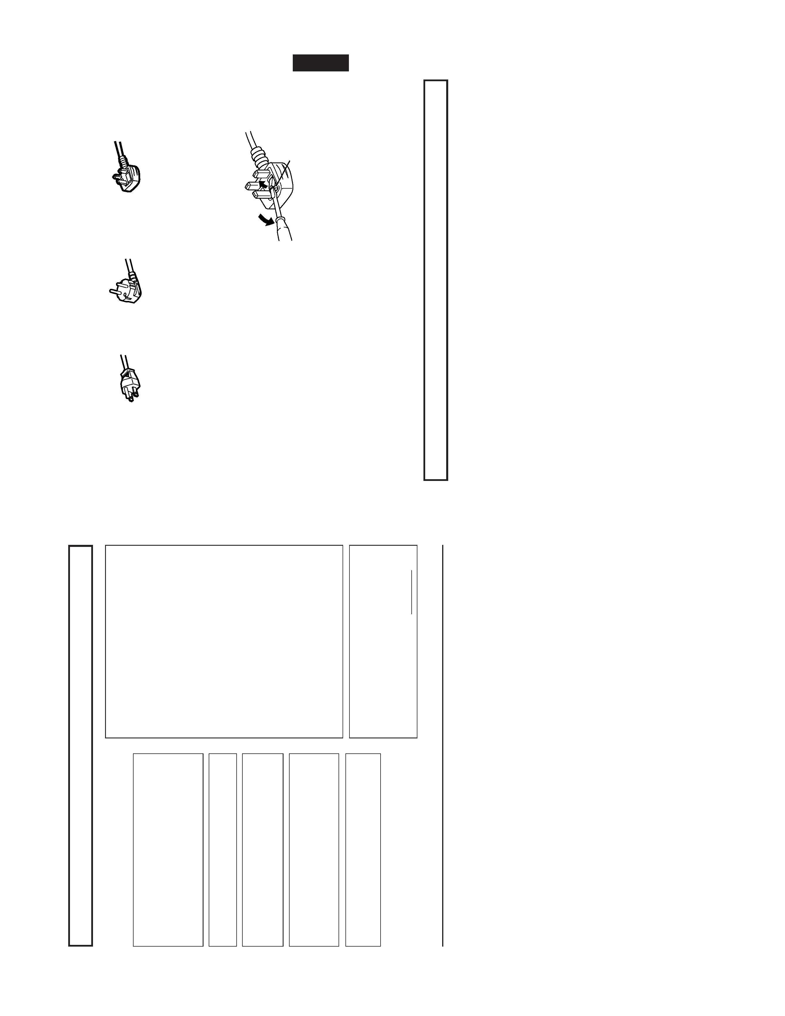
Note
for
the
United
Kingdom
power
cord
only
The
plug
on
the
United
Kingdom
power
cord
has
a
built-in
fuse.
When
replacing
the
fuse,
be
sure
to
use
only
a
correctly
rated
approved
type,
re-fit
the
fuse
cover
.
(Consult
your
dealer
or
qualified
service
personnel.)
How
to
replace
the
fuse
Open
the
fuse
compartment
with
the
blade
screw
driver
,and
replace
the
fuse.
(*
An
example
is
shown
in
the
illustration.)
PRECAUTIONS
Use
only
the
power
source
specified
on
the
unit.
(120
V
AC/230
V
AC,
50
Hz/60Hz)
When
not
using
this
unit
for
a
long
period
of
time,
or
when
cleaning
it,
be
sure
to
disconnect
the
power
plug
from
the
AC
outlet.
Do
not
allow
anything
to
rest
on
the
power
cord.
And
do
not
place
this
unit
where
people
will
tread
on
the
cord.
Do
not
overload
wall
outlets
or
power
cords
as
this
can
result
in
a
fire
or
electric
shock.
A
void
using
this
unit
under
the
following
conditions:
in
extremely
hot,
cold
or
humid
places,
in
dusty
places,
near
appliances
generating
strong
magnetic
fields,
in
places
subject
to
direct
sunlight,
in
badly
ventilated
places,
in
automobiles
with
doors
closed.
Do
not
cover
the
ventilation
slots
while
in
operation
as
this
could
obstruct
the
required
ventilation
flow
.
When
dust
accumulates
on
the
screen
surface,
clean
it
with
a
soft
cloth.
Unplug
this
unit
from
the
AC
outlet
and
refer
servicing
to
qualified
service
personnel
under
the
following
conditions:
when
the
power
cord
is
frayed
or
the
plug
is
damaged,
if
liquid
has
been
spilled
into
the
unit,
if
the
unit
has
been
dropped
or
the
cabinet
has
been
damaged,
when
the
unit
exhibits
a
distinct
change
in
performance.
Do
not
attempt
to
service
this
unit
yourself
as
opening
or
removing
covers
may
expose
you
to
dangerous
voltage
or
other
hazards.
Always
refer
servicing
to
qualified
service
personnel.
When
replacement
parts
are
required,
have
the
service
personnel
verify
in
writing
that
the
replacement
parts
he/she
uses
have
the
same
safety
characteristics
as
the
original
parts.
Use
of
manufacturer
's
specified
replacement
parts
can
prevent
fire,
shock,
or
other
hazards.
Upon
completion
of
any
servicing
or
repair
work
to
this
unit,
please
ask
the
service
personnel
to
perform
the
safety
check
described
in
the
manufacturer
's
service
literature.
When
this
unit
reaches
the
end
of
its
useful
life,
improper
disposal
could
result
in
a
picture
tube
implosion.
Ask
qualified
service
personnel
to
dispose
of
this
unit.
2
SAFETY
PRECAUTIONS
In
order
to
prevent
any
fatal
accidents
caused
by
misoperation
or
mishandling
the
monitor
,be
fully
aware
of
all
the
following
precautions.
W
ARNINGS
T
o
prevent
fire
or
shock
hazard,
do
not
expose
this
monitor
to
rain
or
moisture.
Dangerous
high
voltages
are
present
inside
the
unit.
Do
not
remove
the
back
cover
of
the
cabinet.
When
servicing
the
monitor
,
consult
qualified
service
personnel.
Never
try
to
service
it
yourself.
W
ARNING
:
THIS
APP
ARA
TUS
MUST
BE
EAR
THED.
This
monitor
is
equipped
with
a
3-blade
grounding-type
plug
to
satisfy
FCC
rule.
If
you
are
unable
to
insert
the
plug
into
the
outlet,
contact
your
electrician.
Machine
Noise
Information
Ordinance
3.
GSGV
,
January
18,
1991:
The
sound
pressure
level
at
the
operator
position
is
equal
or
less
than
70
dB(A)
according
to
ISO
7779.
Improper
operations,
in
particular
alternation
of
high
voltage
or
changing
the
type
of
tube
may
result
in
x-ray
emission
of
considerable
dose.
A
unit
altered
in
such
a
way
no
longer
meets
the
standards
of
certification,
and
must
therefore
no
longer
be
operated.
FCC
INFORMATION
(U.S.A.
only)
CAUTION
:Changes
or
modification
not
approved
by
JVC
could
void
the
user's
authority
to
operate
the
equipment.
NOTE
:This
equipment
has
been
tested
and
found
to
comply
with
the
limits
for
a
Class
B
digital
device,
pursuant
to
Part
15
of
the
FCC
Rules.
These
limits
are
designed
to
provide
reasonable
protection
against
harmful
interference
in
a
residential
installation.
This
equipment
generates,
uses
and
can
radiate
radio
frequency
energy
and,
if
not
installed
and
used
in
accordance
with
the
instructions,
may
cause
harmful
interference
to
radio
communications.
However,
there
is
no
guarantee
that
interference
will
not
occur
in
a
particular
installation.
If
this
equipment
does
cause
harmful
interference
to
radio
or
television
reception,
which
can
be
determined
by
turning
the
equipment
off
and
on,
the
user
is
encouraged
to
try
to
correct
the
interference
by
one
or
more
of
the
following
measures:
Reorient
or
relocate
the
receiving
antenna.
Increase
the
separation
between
the
equipment
and
receiver.
Connect
the
equipment
into
an
outlet
on
a
circuit
different
from
that
to
which
the
receiver
is
connected.
Consult
the
dealer
or
an
experienced
radio/TV
technician
for
help.
Notice
(U.S.A.
only)
This
product
utilizes
both
a
Cathode
Ray
T
ube
(CR
T)
and
other
components
that
contain
lead.
Disposal
of
these
materials
may
be
regulated
in
your
community
due
to
environmental
considerations.
For
disposal
or
recycling
information
please
contact
your
local
authorities,
or
the
Electronics
Industries
Alliance:
<http://
www
.eiae.org.>
1-3
TM-A170G
Chroma/Phase
button
[
CHROMA/
PHASE]
Press
this
button
to
activate
the
picture
color
density
adjustment
mode
or
picture
hue
adjustment
mode.
Each
time
you
press
the
button,
the
adjustment
item
changes.
Picture
color
density
f
Picture
hue
Adjust
the
value
with
the
VOLUME/SELECT
buttons
3
.
Also
used
as
a
control
button
in
the
menu
function
mode.
Contrast/Brightness
button
[CONTRAST
/BRIGHT
]
Press
this
button
to
activate
the
picture
contrast
adjust-
ment
mode
or
picture
brightness
adjustment
mode.
Each
time
you
press
the
button,
the
adjustment
item
changes.
Picture
contrast
f
Picture
brightness
Adjust
the
value
with
the
VOLUME/SELECT
buttons
3
.
Also
used
as
a
control
button
in
the
menu
function
mode.
V
olume/Select
buttons
[VOLUME/SELECT
+]
Adjusts
the
sp
eaker
volume.
Also
used
as
a
control
button
in
the
menu
function
mode.
Menu
button
[MENU]
Displays
and
disappears
the
<MENU>
screen.
Pressing
the
CHROMA/PHASE
button
1
with
the
Menu
button
depressed
will
display
the
<SET
-UP
MENU>
screen.
Input
A
(VIDEO)
button
[INPUT
SELECT
A]
Selects
the
video
and
audio
signals
input
to
the
VIDEO
A
!
and
AUDIO
A
$
terminals
on
the
rear
panel.
The
button
lights
when
selected.
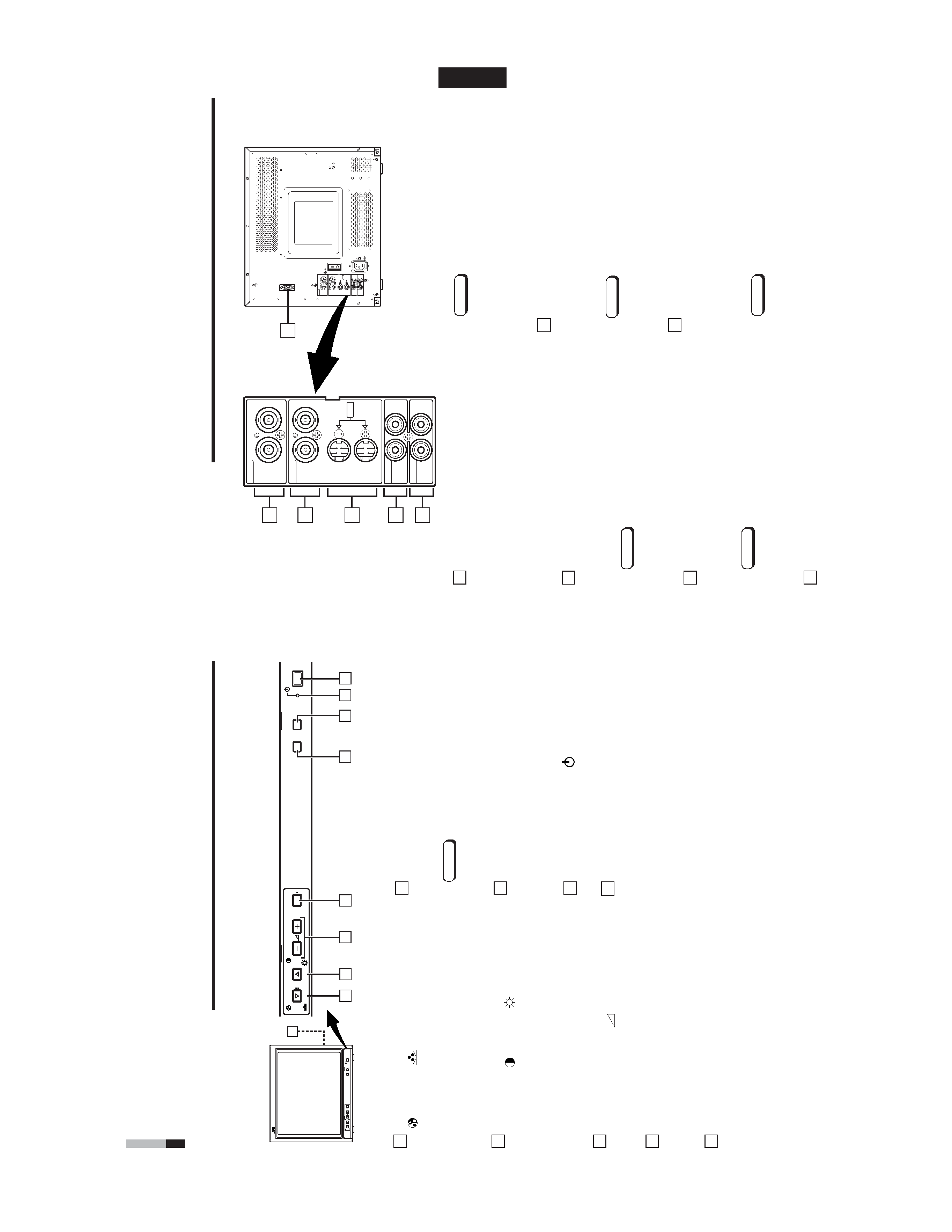
CONTROLS
AND
FEA
TURES
FRONT
VIEW
<Front
Panel>
Input
B
(VIDEO
Y/C)
button
[INPUT
SELECT
B]
Selects
the
video
and
audio
signals
input
to
the
VIDEO
B
@
or
VIDEO
B
(Y/C)
#
and
AUDIO
B
%
terminals
on
the
rear
panel.
The
button
lights
when
selected.
Note:
The
VIDEO
B
terminals
include
a
video
terminal
(BNC
connector)
and
a
Y/C
terminal
(mini-DIN
4-pin
connec-
tor).
The
Y/C
(S-video)
terminal
has
priority
.
Power
indicator
Unlit
:
The
main
power
is
OFF
.
Orange
:
The
main
power
is
ON,
but
the
monitor
's
power
is
OFF
(in
the
stand-by
mode).
Green
:
The
main
power
is
ON,
and
the
monitor
's
power
is
ON
(in
the
normal
operation
mode).
Power
switch
[POWER
]
Press
the
power
switch
to
turn
the
monitor
's
power
ON
or
OFF
when
the
main
power
is
ON.
Speaker
A
built-in
speaker
is
located
inside
the
right
side
panel
when
the
monitor
is
viewed
from
the
front.
1
2
3
4
5
6
7
8
9
4
5
7
6
PO
WER
CHR
OMA
MENU
INPUT
SELECT
PHASE
5
0C
BRIGHT
CONTRAST
V
OLUME/SELECT
AB
8
4
3
2
1
9
PO
WER
CHR
OMA
MENU
INPUT
SELECT
PHASE
TM-A170
BRIGHT
CONTRAST
V
O
LUME/SELECT
AB
ENGLISH
External
control
terminal
[REMOTE]
Remote
terminal
for
external
control.
The
input
signal
(the
INPUT
function)
or
the
aspect
ratio
(the
ASPECT
RA
TIO
function)
can
be
selected
by
external
control
using
a
switch
cable.
Setting
of
the
INPUT
REMOTE
or
ASPECT
REMOTE
item
in
the
<SET
-
UP
MENU>
screen
is
required
before
using
external
control.
Refer
to
the
HOW
T
O
USE
EXTERNAL
CONTROL
on
page
14
for
more
details.
V
ideo
A
terminals
[VIDEO
A
IN/OUT]
V
ideo
signal
input
(IN)
and
output
(OUT)
terminals.
The
output
terminal
is
bridge-connected.
IN
:V
ideo
signal
input
terminal
OUT
:Bridge-connected
video
signal
output
terminal
Notes:
*
For
corresponding
audio
signals,
use
the
AUDIO
A
terminals
$
.
*
Also
refer
to
BASIC
CONNECTION
EXAMPLE
on
page
12.
V
ideo
B
terminals
[VIDEO
B
IN/OUT]
V
ideo
signal
input
(IN)
and
output
(OUT)
terminals.
The
output
terminal
is
bridge-connected.
IN
:
V
ideo
signal
input
terminal
OUT
:
Bridge-connected
video
signal
output
terminal
Notes:
*
For
corresponding
audio
signals,
use
the
AUDIO
B
terminals
%
.
*
Also
refer
to
BASIC
CONNECTION
EXAMPLE
on
page
12.
V
ideo
B
(Y/C)
terminals
[VIDEO
B
Y/C
IN/OUT]
Y/C
(S-video)
signal
input
(IN)
and
output
(OUT)
termi-
nals.
The
output
terminal
is
bridge-connected.
IN
:
Y/C-separated
(S-video)
video
signal
input
terminal
OUT
:
Bridge-connected
Y/C-separated
(S-video)
signal
output
terminal.
REAR
VIEW
<Rear
Panel>
10
11
12
13
5
Notes:
*
For
corresponding
audio
signals,
use
the
AUDIO
B
terminals
%
.
*
When
both
VIDEO
B
terminals
are
connected
(input)
at
the
same
time,
the
Y/C
terminal
has
priority
.
*
Also
refer
to
BASIC
CONNECTION
EXAMPLE
on
page
13.
Audio
A
terminals
[AUDIO
A
IN/OUT]
Input
(IN)
and
output
(OUT)
terminals
for
the
audio
signal
corresponding
to
the
VIDEO
A
terminals
!
.
The
output
terminal
is
bridge-connected.
IN
:
Audio
signal
input
terminal
OUT
:Bridge-connected
audio
signal
output
terminal
Notes:
*
For
corresponding
video
signals,
use
the
VIDEO
A
terminal
!
.
*
Also
refer
to
BASIC
CONNECTION
EXAMPLE
on
page
12.
Audio
B
terminals
[AUDIO
B
IN/OUT]
Input
(IN)
and
output
(OUT)
terminals
for
the
audio
signals
corresponding
to
the
VIDEO
B
terminals
@
VIDEO
B
(Y/C)
#
.
The
output
terminal
is
bridge-connected.
IN
:
Audio
signal
input
terminal
OUT
:Bridge-connected
audio
signal
output
terminal
Notes:
*For
corresponding
video
signals,
use
the
VIDEO
B
terminals
@
or
VIDEO
B
(Y/C)
terminals
#
.
*
Also
refer
to
BASIC
CONNECTION
EXAMPLE
on
pages
12
and
13.
14
11
10
12
13
14
15
VIDEO
A
REMOTE
AUDIO
A
AUDIO
B
VIDEO
B
IN
OUT
IN
IN
IN
OUT
OUT
IN
OUT
Y/C
OUT
VIDEO
A
AUDIO
A
AUDIO
B
VIDEO
B
IN
OUT
IN
IN
IN
OUT
OUT
IN
OUT
Y/C
OUT
15
1-4
TM-A170G
ENGLISH
PA
L
VOLUME
:
2
0
PHASE
:
0
0
+
Item
s
VOLUME/SELECT
button
+
CHROMA
lighter
deeper
(Chroma)
PHASE
reddish
greenish
(Phase)
CONTRAST
lower
higher
(Contrast)
BRIGHT
darker
brighter
(Brightness)
ST
A
TUS
indication
(P
AL
or
NTSC)
00
~
50
HOW
TO
HANDLE
BASIC
OPERA
TIONS
BASIC
OPERA
TION
PICTURE
ADJUSTMENT
2.
Press
the
POWER
switch
to
turn
on
the
power
.
ON
:
Power
turns
ON.
(Power
indicator:
lit)
Green:
The
main
power
is
ON,
and
the
monitor
's
power
is
ON
(in
the
normal
operation
mode).
OFF
:
Power
turns
OFF
.(Power
indicator:
unlit)
Orange
:
The
main
power
is
ON,
but
the
monitor
's
power
is
OFF
(in
the
standby
mode)
Unlit
:
The
main
power
is
OFF
.
3.
Press
the
INPUT
SELECT
buttons
to
choose
input.
Select
video/audio
signals
input
to
terminals
on
the
rear
panel.
The
selected
button
lights
in
green.
4.
Press
the
VOLUME/SELECT
buttons
to
adjust
the
speaker
volume.
Press
this
button
to
display
the
speaker
volume
level
on
the
screen.
+
:
The
Built-in
speaker
volume
is
increased.
(00
=
50)
:
The
Built-in
speaker
volume
is
decreased.
(50
=
00)
*
S
creen
indication
will
disappear
about
10
seconds
after
operating.
*
T
he
on-screen
display
goes
of
fwhen
you
press
MENU
button.
1.
Press
select
buttons
corresponding
to
the
item
you
want
to
adjust.
The
item
you
select
is
displayed
on
the
screen.
1
Chroma
control
:Press
the
CHROMA/PHASE
button
once.
2
Phase
control
:Press
the
CHROMA/PHASE
button
twice.
3
Contrast
control
:Press
the
CONTRAST/BRIGHT
button
once.
4
Brightness
control
:Press
the
CONTRAST/BRIGHT
button
twice.
*
P
ressing
the
CHROMA/PHASE
button
and
CONTRAST/BRIGHT
button
alternately
while
the
item
is
shown
on
screen
restores
the
previous
status.
When
no
item
is
shown
on
screen,
CHROMA
and
CONTRAST
have
priority
.
*
S
creen
indication
will
disappear
about
10
seconds
after
operating.
*
T
he
on-screen
display
goes
of
fwhen
you
press
MENU
button.
About
the
ST
A
TUS
indication
W
ith
the
COLOR
SYSTEM
setting
set
to
AUT
O
mode,
when
you
turn
on
the
power
or
select
inputs,
the
color
system
indication
appears
for
about
3
seconds
on
the
screen
while
P
AL
or
NTSC
signals
are
being
detected.
It
does
not
appear
when
receiving
a
B/W
signal
or
when
no
signal
is
input.
Refer
to
page
8
for
more
information
about
COLOR
SYSTEM
setting
and
page
9
for
more
information
about
ST
A
TUS
indication
setting.
Notes:
Phase
control
is
ef
fective
only
in
the
NTSC
color
system
mode.
Chroma
control
is
not
ef
fective
when
receiving
B/W
or
when
no
signal
is
input.
W
hen
CHROMA
is
adjusted
to
"40,"
the
picture
becomes
less
colorful.
"NO
EFFECT"
is
displayed
(for
about
3
seconds)
when
your
selected
function
has
no
ef
fect.
2.
Adjust
with
the
VOLUME/SELECT
buttons.
+
7
PO
WER
V
OLUME/SELECT
CHR
OMA
PHASE
BRIGHT
CONTRAST
V
OLUME/SELECT
VIDEO
B
(Y/C)
terminal
1.
Press
the
main
power
switch
to
turn
on
the
power
.
INPUT
SELECT
AB
T
e
rminals
on
the
rear
panel
V
ideo
signal
input
Audio
signal
input
1
Input
A
VIDEO
A
terminal
AUDIO
A
terminal
(VIDEO)
2
Input
B
VIDEO
B
terminal
AUDIO
B
terminal
(VIDEO
Y
/C)
INPUT
SELECT
buttons
Note:The
Y/C
(S-video)
terminal
has
priority
.
17
16
18
18
VIDEO
A
REMOTE
AUDIO
A
AUDIO
B
VIDEO
B
IN
OUT
IN
IN
IN
OUT
OUT
IN
OUT
Y/C
OUT
18
REAR
VIEW
<Rear
Panel>
CONTROLS
AND
FEA
TURES
(cont'd)
6
Main
power
switch
Press
the
switch
to
turn
the
main
power
ON
or
OFF
.
When
the
main
power
is
ON,
the
power
indicator
on
the
front
panel
lights
in
orange
and
the
monitor
enters
the
stand-by
mode.
I:
ON
:
OFF
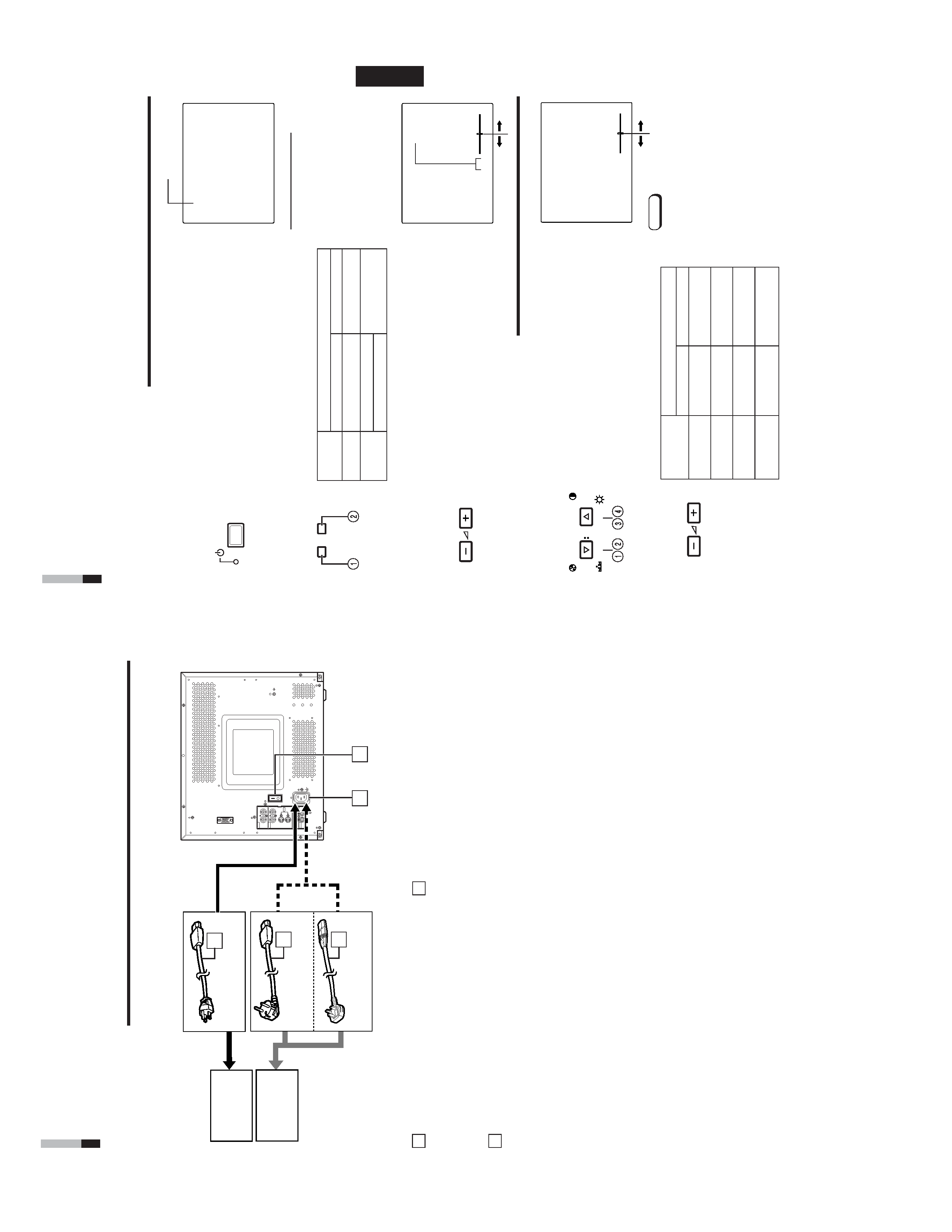
AC
inlet
[AC
IN]
Power
input
connector
.Connect
the
provided
AC
power
cord
*
to
an
AC
outlet
(120
V
AC
or
230
V
AC,
50
Hz/60
Hz).
T
o
AC
outlet
(230
V
AC,
50
Hz/60
Hz)
For
the
United
Kingdom
For
Europe
Power
cord
Connects
the
provided
power
cord
(120
V
AC
or
230
V
AC,
50
Hz/60
Hz)
to
the
AC
IN
connector
&
.
Caution:
In
North
America
(USA
and
Canada),
this
monitor
comes
with
one
power
cable.
In
Europe
and
the
United
King-
dom,
two
power
cables
are
provided
(one
for
use
in
continental
European
countries
and
the
other
for
the
UK).
Be
sure
to
use
the
power
cable
that
is
appropriate
for
the
AC
outlets
used
in
your
region.
If
none
of
the
power
cables
provided
is
suitable,
please
contact
your
dealer
or
qualified
service
personnel
to
obtain
the
correct
type
of
power
cable.
16
17
18
T
o
AC
outlet
(120
V
AC,
50
Hz/60
Hz)
For
U.S.A.
and
Canada
1-5
TM-A170G
8
EXIT
CHR
OMA
MENU
PHASE
BRIGHT
CONTRAST
V
O
LUME/SELECT
<M
E
N
U
>
SHARPNESS
:
00
COLOR
TEMP
.
:
6500
COLOR
SYSTEM
:
AUT
O
ASPECT
RA
TIO
:
4-3
Menu
items
Purpose
Setting
range
SHARPNESS
Picture
sharpness
COLOR
TEMP
.
Color
temperature
of
white
balance
COLOR
SYSTEM
Color
system
ASPECT
RA
T
IO
Aspect
ratio
Front
panel
Function
Contents
button
d
isplayed
+
Increases
(to
max.
value)
4
Forwards
the
setting
value
Decreases
(to
min.
value)
1
Reverses
the
setting
value
VOLUME/
SELECT
()
VOLUME/
SELECT
(+)
Front
panel
Function
Contents
button
displayed
CHROMA/
Forwards
selection
mark
(4
)
PHASE
CONTRAST/
Reverses
selection
mark
(
4
)
BRIGHT
Front
panel
Function
Contents
button
d
isplayed
MENU
EXIT
Quits
(or
Releases)
the
<MENU>
screen
1
2
3
4
HOW
TO
USE
THE
MENU
FUNCTIONS
·
SHARPNESS
·
COLOR
SYSTEM
·
COLOR
TEMP
.
·
ASPECT
RA
TIO
Y
ou
can
set
the
following
menu
items.
Set
them
depending
on
your
needs.
1.
Press
the
MENU
button.
The
<MENU>
screen
is
displayed.
*
The
on-screen
display
goes
of
fautomatically
after
about
five
minutes
with
operation
performed.
2.
Press
the
CHROMA/PHASE
or
CONTRAST/BRIGHT
button
to
select
MENU
items.
A
selection
mark
(
4
)is
put
next
to
the
selected
item.
SHARPNESS
COLOR
TEMP.
COLOR
SYSTEM
ASPECT
RATIO
3.
Press
the
VOLUME/SELECT
buttons
to
set.
4.
If
you
want
to
set
the
other
menu
items,
repeat
procedures
2
and
3.
5.
Press
the
MENU
button
to
quit.
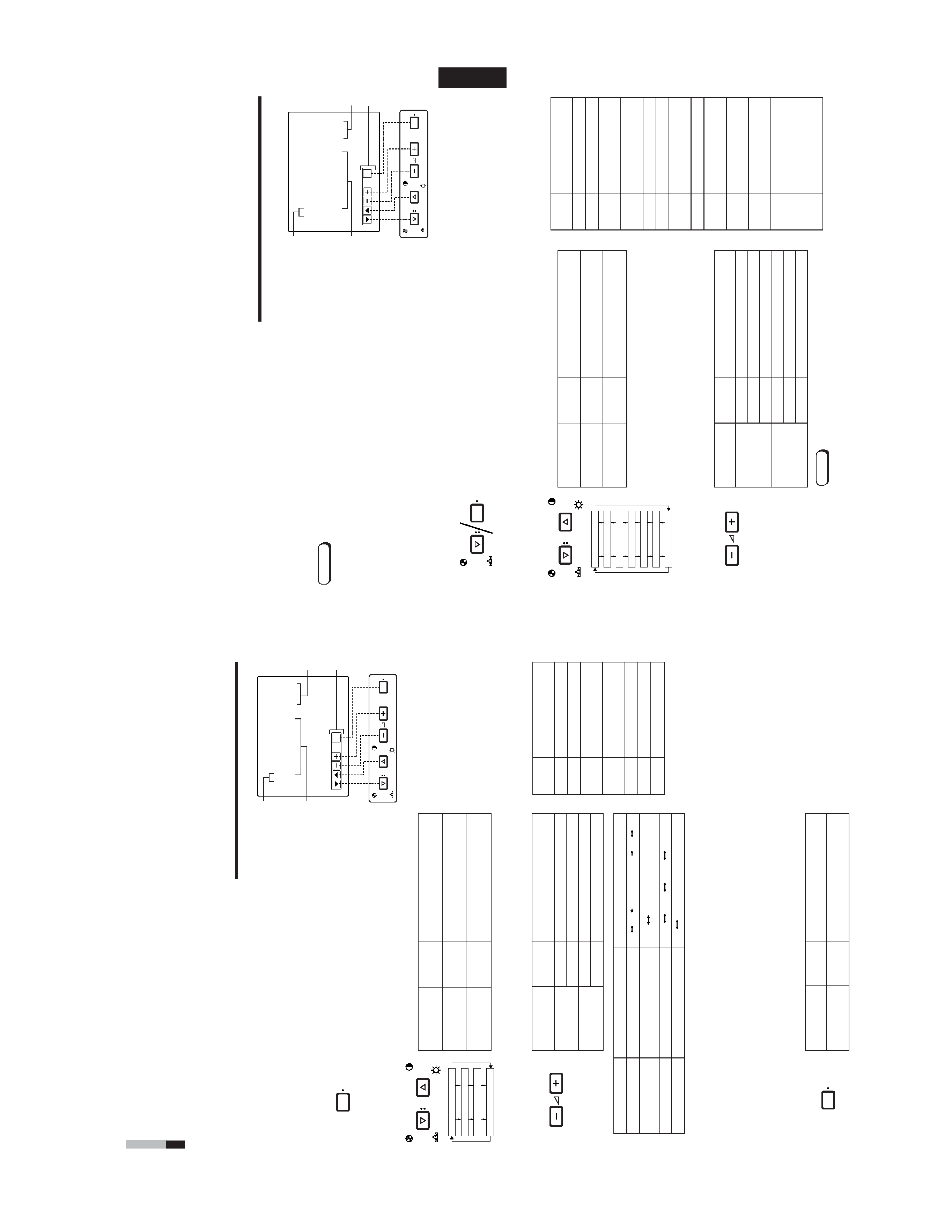
1
Selection
mark
(
4
):
Indicates
the
menu
item
you
select.
2
Menu
item:
Menu
items
you
can
select.
3
Setting
display:
Indicates
the
current
settings
(value).
4
Function
display:
The
functions
of
the
front
panel
buttons
(5
buttons
on
the
left)
correspond
to
the
function
displayed.
<MENU>
screen
<Front
panel
buttons>
Function
Contents
displayed
Forwards
the
menu
item.
Reverses
the
menu
item.
Lowers
the
adjustment
value.
(to
the
minimum)
+
Raises
the
adjustment
value.
(to
the
maximum)
4
Forward
s
the
setting
value.
1
Reverses
the
setting
value.
EXIT
E
xits
the
<MENU>
screen.
DISPLA
Y
AND
SELECTION
IN
THE
<MENU>
SCREEN
MODE
(SETTING)
MENU
CHR
OMA
PHASE
BRIGHT
CONTRAST
V
O
LUME/SELECT
MENU
00
+01
+39
+40
··
·
·
·
·
·
·
·
·
·
·
6500
9300
AUTO
NTSC
AUTO
PAL
*
F
or
normal
use,
leave
the
COLOR
SYSTEM
setting
to
AUT
O.
If
reception
is
unsatisfactory
in
AUT
O
position,
set
it
to
the
appropriate
color
system
mode
(NTSC
or
P
A
L).
*
W
hen
ASPECT
REMOTE
in
the
<SET
-UP
MENU>
screen
is
set
to
ON,
"REMOTE"
is
displayed
on
the
ASPECT
RA
T
IO
setting
and
the
aspect
ratio
cannot
be
changed
from
the
<MENU>
screen.
4
-3
1
6
-9
When
the
screen
aspect
ratio
is
set
to
16
-
9
(16:9)
in
ASPECT
RA
T
IO,
the
picture
will
be
vertically
reduced.
ENGLISH
EXIT
CHR
OMA
MENU
PHASE
BRIGHT
CONTRAST
V
OLUME/SELECT
DISPLA
Y
AND
SELECTIONS
IN
THE
<SET
-UP
MENU>
MODE
(SETTING)
·
H
.POSITION
·
CONTROL
LOCK
·
ASPECT
REMOTE
·
V
.POSITION
·
S
T
A
TUS
DISPLA
Y
·
W
HITE
BALANCE
·
INPUT
REMOTE
Y
ou
can
set
the
following
set-up
menu
items.
1.
While
pressing
the
MENU
button,
press
the
CHROMA/PHASE
button.
The
<SET
-UP
MENU>
screen
is
displayed.
2.
Press
the
CHROMA/PHASE
or
CONTRAST/BRIGHT
button
to
select
the
desired
menu
item.
A
selection
mark
(
4
)is
put
next
to
the
selected
item.
3.
Press
the
VOLUME/SELECT
buttons
to
set.
For
WHITE
BALANCE
items,
select
the
CUT
OFF
or
DRIVE
setting
screen,
then
select
the
function
display
for
adjustment.
Press
the
EXIT
(MENU)
button
to
return
to
the
<SET
-UP
MENU>
screen.
Notes:
<SET
-UP
MENU>
screen
<Front
panel
buttons>
1
Selection
mark
(
4
):
Indicates
the
menu
item
you
select.
2
Menu
item:
Menu
items
you
can
select.
3
Setting
display:
Indicates
the
current
settings
(value).
4
Function
display:
T
he
functions
of
the
front
panel
buttons
(5
buttons
on
the
left)
correspond
to
the
function
displayed.
Function
Contents
displayed
Forwards
the
menu
item.
Reverses
the
menu
item.
Lowers
the
adjustment
value.
(to
the
minimum)
+
R
aises
the
adjustment
value.
(to
the
maximum)
4
Forwards
the
setting
value.
1
Reverses
the
setting
value.
EXIT
Exits
the
<SET
-UP
MENU>
screen.
D
R
V
S
elects
DRIVE
adjustment.
CUT
O
Selects
CUT
OFF
adjustment.
RB
Adjusts
red
and
blue
signal
level.
RGB
Adjusts
red,
green
and
blue
signal
level.
DISP
T
u
rns
the
ON-SCREEN
display
on
or
of
f.
(This
function
is
ef
fective
only
in
the
DRIVE
or
CUT
OFF
adjustment
mode.)
Front
panel
Function
Contents
button
d
isplayed
CHROMA/
Forwards
selection
mark
(4
)
PHASE
CONTRAST/
Reverses
selection
mark
(4
)
BRIGHT
Front
panel
Function
Contents
button
d
isplayed
+
Increases
(to
max.
value)
4
Forwards
the
setting
value
CUT
O
Selects
CUT
OFF
setting
screen
Decreases
(to
min.
value)
1
Reverses
the
setting
value
DR
V
Selects
DRIVE
setting
screen
VOLUME/
SELECT
()
VOLUME/
SELECT
(+)
Parameters
for
H.
POSITION
and
V
.POSITION
can
be
set
separately
depending
on
the
signal
(Input
A
(VIDEO),
Input
B
(VIDEO)
or
Input
B
(Y/C))
selected
with
the
input
select
buttons
on
the
front
panel.
Select
the
required
video
input
with
the
input
select
buttons
on
the
front
panel
in
advance.
WHITE
BALANCE
can
be
set
independently
at
6500
or
9300
for
the
color
temperature
value.
Set
COLOR
TEMP
.to
6500
or
9300
on
the
<MENU>
screen
beforehand.
Notes:
<SET
-UP
MENU>
H.
POSITION
:
00
V
.POSITION
:
00
WHITE
BALANCE
CONTROL
LOCK
:
O
FF
ST
A
TUS
DISPLA
Y
:
ON
INPUT
REMOTE
:
OFF
ASPECT
REMOTE
:
OFF
1
2
3
4
H.
POSITION
V.
POSITION
WHITE
BALANCE
CONTROL
LOCK
STATUS
DISPLAY
INPUT
REMOTE
ASPECT
REMOTE
MENU
CHR
OMA
PHASE
CHR
OMA
PHASE
BRIGHT
CONTRAST
V
OLUME/SELECT
9