COLOR MONITOR
SyncMaster 330TFT
SyncMaster 530TFT
SyncMaster 331TFT
SyncMaster 531TFT
Manual
SERVICE
COLOR MONITOR
CONTENTS
+
-
EXIT
MENU
SAMSUNG
1. Precautions
2. Reference Information
3. Product Specifications
4. Operating Instructions
5. Disassembly & Reassembly
6. Troubleshooting
7. Exploded View & Parts List
8. Block Diagram
9. Electrical Parts List
10. PCB Diagrams
11. Wiring Diagram
12. Schematic Diagrams

Samsung Electronics Co., Ltd. July 1998
Printed in Korea
Code No.: BN68-60017A
1-1-1 Warnings
1.
For continued safety, do not attempt to modify the
circuit board.
2.
Disconnect the AC power and DC Power Jack
before servicing.
3.
When the chassis is operating, semiconductor
heatsinks are potential shock hazards.
1-1-2 Servicing the LCD Monitor
1.
When servicing the LCD Monitor, remove the static
charge by connecting a 10k ohm resistor in series
with an insulated wire (such as a test probe)
between the chassis and the anode lead.
(Disconnect the AC line cord from the AC outlet.)
2.
It is essential that service technicians have an
accurate voltage meter available at all times. Check
the calibration of this meter periodically.
1-1-3 Fire and Shock Hazard
Before returning the monitor to the user, perform the
following safety checks:
1.
Inspect each lead dress to make certain that the
leads are not pinched or that hardware is not
lodged between the chassis and other metal parts in
the monitor.
2.
Inspect all protective devices such as nonmetallic
control knobs, insulating materials, cabinet backs,
adjustment and compartment covers or shields,
isolation resistor-capacitor networks, mechanical
insulators, etc.
3.
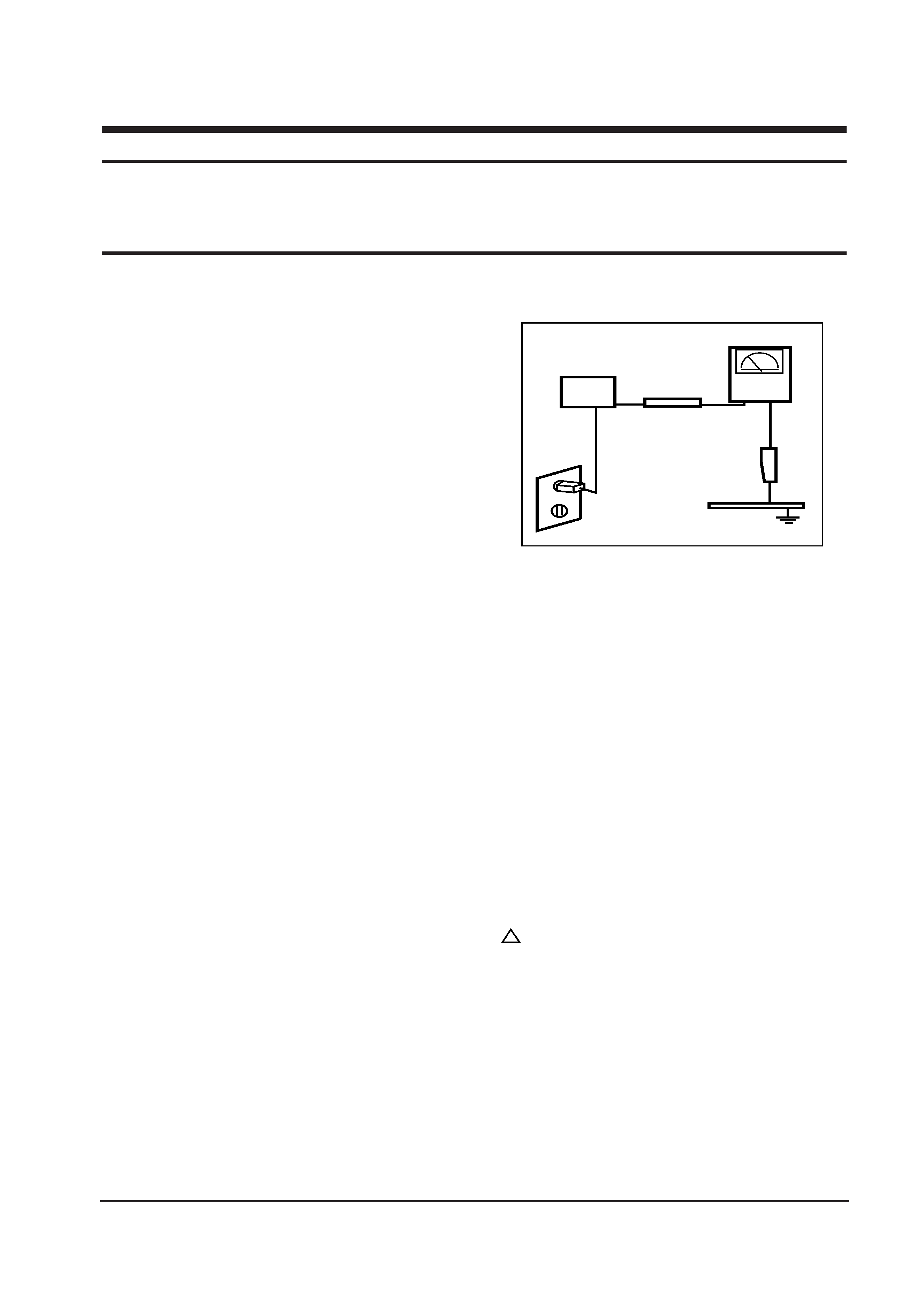
Leakage Current Hot Check (Figure 1-1): WARNING:
Do not use an isolation transformer during this test.
Use a leakage current tester or a metering system
that complies with American National Standards
Institute (ANSI C101.1, Leakage Current for
Appliances), and Underwriters Laboratories (UL
Publication UL1410, 59.7).
Figure 1-1. Leakage Current Test Circuit
4.
With the unit completely reassembled, plug the AC
line cord directly into a 120V AC outlet. With the
unitÕs AC switch first in the ON position and then
OFF, measure the current between a known earth
ground (metal water pipe, conduit, etc.) and all
exposed metal parts, including: metal cabinets,
screwheads and control shafts. The current
measured should not exceed 0.5 milliamp. Reverse
the power-plug prongs in the AC outlet and repeat
the test.
1-1-4 Product Safety Notices
Some electrical and mechanical parts have special
safety-related characteristics which are often not
evident from visual inspection. The protection they give
may not be obtained by replacing them with
components rated for higher voltage, wattage, etc. Parts
that have special safety characteristics are identified by
on schematics and parts lists. A substitute
replacement that does not have the same safety
characteristics as the recommended replacement part
might create shock, fire and / or other hazards. Product
safety is under review continuously and new
instructions are issued whenever appropriate.
SyncMaster 33*TFT/53*TFT
1-1
1 Precautions
Follow these safety, servicing and ESD precautions to prevent damage and to protect against potential hazards such as
electrical shock.
1-1 Safety Precautions
DEVICE
UNDER
TEST
TEST ALL
EXPOSED METAL
SURFACES
(READING SHOULD
NOT BE ABOVE 0.5mA)
LEAKAGE
CURRENT
TESTER
2-WIRE CORD
ALSO TEST WITH
PLUG REVERSED
(USING AC ADAPTER
PLUG AS REQUIRED)
EARTH
GROUND
!

1-2-1 General Servicing Precautions
1.
Always unplug the unitÕs AC power cord from the
AC power source and disconnect the DC Power
Jack before attempting to:
(a) remove or reinstall any component or assembly,
(b) disconnect PCB plugs or connectors, (c) connect
a test component in parallel with an electrolytic
capacitor.
2.
Some components are raised above the printed
circuit board for safety. An insulation tube or tape
is sometimes used. The internal wiring is
sometimes clamped to prevent contact with
thermally hot components. Reinstall all such
elements to their original position.
3.
After servicing, always check that the screws,
components and wiring have been correctly
reinstalled. Make sure that the area around the
serviced part has not been damaged.
1.
Immediately before handling any semiconductor
components or assemblies, drain the electrostatic
charge from your body by touching a known earth
ground. Alternatively, wear a discharging wrist-
strap device. To avoid a shock hazard, be sure to
remove the wrist strap before applying power to
the monitor.
2.
After removing an ESD-equipped assembly, place it
on a conductive surface such as aluminum foil to
prevent accumulation of an electrostatic charge.
3.
Do not use freon-propelled chemicals. These can
generate electrical charges sufficient to damage
ESDs.
4.
Use only a grounded-tip soldering iron to solder or
desolder ESDs.
5.
Use only an anti-static solder removal device. Some
solder removal devices not classified as Òanti-staticÓ
can generate electrical charges sufficient to damage
ESDs.
4.
Check the insulation between the blades of the AC
plug and accessible conductive parts (examples:
metal panels, input terminals and earphone jacks).
5.
Insulation Checking Procedure: Disconnect the
power cord from the AC source and turn the power
switch ON. Connect an insulation resistance meter
(500 V) to the blades of the AC plug.
The insulation resistance between each blade of the
AC plug and accessible conductive parts (see
above) should be greater than 1 megohm.
6.
Always connect a test instrumentÕs ground lead to
the instrument chassis ground before connecting the
positive lead; always remove the instrumentÕs
ground lead last.
6.
Do not remove a replacement ESD from its
protective package until you are ready to install it.
Most replacement ESDs are packaged with leads
that are electrically shorted together by conductive
foam, aluminum foil or other conductive materials.
7.
Immediately before removing the protective
material from the leads of a replacement ESD,
touch the protective material to the chassis or
circuit assembly into which the device will be
installed.
Caution: Be sure no power is applied to the
chassis or circuit and observe all
other safety precautions.
8.
Minimize body motions when handling
unpackaged replacement ESDs. Motions such as
brushing clothes together, or lifting your foot from
a carpeted floor can generate enough static
electricity to damage an ESD.
1 Precautions
1-2
SyncMaster 33*TFT/53*TFT
1-3 Electrostatically Sensitive Devices (ESD) Precautions
Some semiconductor (solid state) devices can be easily damaged by static electricity. Such components are commonly
called Electrostatically Sensitive Devices (ESD). Examples of typical ESD devices are integrated circuits and some field-
effect transistors. The following techniques will reduce the incidence of component damage caused by static electricity.
1-2 Servicing Precautions
WARNING:
An electrolytic capacitor installed with the wrong polarity might explode.
Caution:
Before servicing units covered by this service manual, read and follow the Safety Precautions
section of this manual.
Note:
If unforeseen circumstances create conflict between the following servicing precautions and any of the
safety precautions, always follow the safety precautions.
SyncMaster 33*TFT/53*TFT
2-1
2 Reference Information
2-1 List of Abbreviations, Symbols and Acronyms
2-1-1 Abbreviations
Abbreviation
Definition
Abbreviation
Definition
AUTO_MENB
AUTO ENABLE (NEG.)
AUTO_SOG
SINK ON GREEN ENABLE
BL_EN
LCD PANEL BACK LIGHT ENABLE
BRIGHT
BRIGHTNESS CONTROL
DAB(7:0)
BLUE COLOR DATA (ODD) FROM IC305
DAG(7:0)
GREEN COLOR DATA (ODD) FROM IC305
DAR(7:0)
RED COLOR DATA (ODD) FROM IC305
DBB(7:0)
BLUE COLOR DATA (EVEN) FROM IC305
DBG(7:0)
GREEN COLOR DATA (EVEN) FROM IC305
DBR(7:0)
RED COLOR DATA (EVEN) FROM IC305
DDC_SCL
DDC I2C CLOCK FROM PC
DDC_SDA
DDC I2C DATA FROM PC
DEN
LVDS DATA ENABLE
DFSYNCB
CONTROL SIGNAL FROM IC301 TO IC305
DHCLK
DOT CLOCK FOR PANEL DRIVING
DHS
LVDS HSYNC
DREFCLK1
67MHz OSC CLK FOR IC305
DV_BLU
OSD BLUE DATA
DV_FBK
OSD ENABLE
DV_GRN
OSD GREEN DATA
DV_RED
OSD RED DATA
DVACTIV1B
HSYNC FOR OSD (NEG.)
DVCLK
DOT CLOCK FOR OSD
DVS
LVDS VSYNC
DVSYNCB
VSYNC FOR OSD (NEG.)
FSD(47:0)
VIDEO DATA BETWEEN IC301 AND
IC302,IC303,IC304
HSYNC_PLL
HSYNC FOR PLL
INVERT
INTERLACE CONTROL SIGNAL
KEY1
FUNCTION KEY SIGNAL1 TO MICOM
KEY2
FUNCTION KEY SIGNAL2 TO MICOM
LED
LED ON
LVDS_DATA
DATA OUTPUT FROM IC310, IC311
LVDS_EN
LVDS ENABLE
M_HSYNC
BUFFERED MICOM OUTPUT HSYNC
M_HSYNC1
MICOM OUTPUT HSYNC
M_VSYNC
BUFFERED MICOM OUTPUT VSYNC
M_VSYNC1
MICOM OUTPUT VSYNC
OSCOUT
BUFFERED 24MHz CLOCK
OSCOUT1
24MHz CLOCK
PANEL_EN
+12V_PANEL/+5V_PANEL ENABLE
PC_BLUE_IN
BLUE COLOR SIGNAL FROM PC
PC_GREEN_IN
GREEN COLOR SIGNAL FROM PC
PC_HSYNC_IN
HSYNC FROM PC
PC_RED_IN
RED COLOR SIGNAL FROM PC
PC_VSYNC_IN
VSYNC FROM PC
PCBLUE(7:0)
BLUE COLOR DATA FROM IC101
PCCLAMP
BUFFERED VIDEO CLAMP SIGNAL
PCCLAMP1
VIDEO CLAMP SIGNAL
PCCLK
PLL CLOCK OUT FOR IC301
PCCLK2
PLL CLOCK OUT FOR IC405
PCCLK3
PLL CLOCK OUT FOR IC110
PCGREEN(7:0)
GREEN COLOR DATA FROM ADC(IC101)
PCRED(7:0)
RED COLOR DATA FROM IC101
PCVSYNC2
BUFFERED VSYNC
RESETB
RESET (NEG.)
RGB_HSYNC
HSYNC FOR MICOM(IC401)
RGB_VSYNC
VSYNC FOR MICOM(IC401)
SCL
I2C CLOCK
SCSB
IC305 ENABLE
SDA
I2C DATA
SOG_CSYNC
COMPOSITE SYNC FROM SOG
SOURCE_PC
SELF RASTER CHECK SIGNAL
SPI_MISO
SERIAL INPUT DATA CONTROL
SPI_MOSI
SERIAL OUTPUT DATA CONTROL
SPI_SCK
SERIAL CLOCK
SW_REG_ENB
POWER ON/OFF CONTROL
VAIL_CSB
IC301 ENABLE
VCBLNKB
CONTROL SIGNAL FROM IC305 TO IC301
VCC
DC 5V FOR MICOM(IC401)
VCLREQB
CONTROL SIGNAL FROM IC305 TO IC301
VGABLUE(7:0)
NC
VGAGREEN(7:0)
NC
VGARED(7:0)
NC
VGBBLUE(7:0)
BLUE COLOR DATA FROM IC301
VGBGREEN(7:0)
GREEN COLOR DATA FROM IC301
VGBRED(7:0)
RED COLOR DATA FROM IC301