COLOR MONITOR
CHA4217L
CHA4227L
CHA5807L
CHA5227L
Manual
SERVICE
COLOR MONITOR
CONTENTS
1. Precautions
2. Reference Information
3. Product Specifications
4. Operating Instructions
5. Disassembly & Reassembly
6. Alignment & Adjustments
7. Troubleshooting
8. Exploded View & Parts List
9. Electrical Parts List
10. Block Diagram
11. PCB Diagrams
12. Wiring Diagram
13. Schematic Diagrams

Samsung Electronics Co., Ltd. August 1998
Printed in Korea
Code No.: BH68-61127A
WARNINGS
1.
For continued safety, do not attempt to modify the
circuit board.
2.
Disconnect the AC power before servicing.
3.
When the chassis is operating, semiconductor
heatsinks are potential shock hazards.
1-1-1
Servicing the High Voltage VR
and CRT :
WARNING:Damaged IC202 may cause excessive
x-ray emissions.
1.
When servicing the high voltage system, remove
the static charge by connecting a 10 kohm resistor
in series with an insulated wire (such as a test
probe) between the chassis and the anode lead.
2.
If the HV VR requires adjustment:
This monitor does not need to adjust high voltage,
high voltage step is saved at IC202, adjusting this
high voltage to 24.5±0.5 kV - 14Ó, 25.0±0.5 kV - 15Ó.
3.
When troubleshooting a monitor with excessively
HV, avoid being unnecessarily close to the monitor.
Do not operate the monitor for longer than is
necessary to locate the cause of excessive voltage.
4.
High voltage should always be kept at the rated
value, no higher. Only when high voltage is
excessive are X-rays capable of penetrating the shell
of the CRT, including the lead in glass material.
Operation at high voltages may also cause failure of
the CRT or high voltage circuitry.
5.
When the HV regulator is operating properly, there
is no possibility of an X-ray problem. Make sure the
HV does not exceed its specified value and that it is
regulating correctly.
6.
The CRT is especially designed to prohibit
X-ray emissions. To ensure continued X-ray
protection, replace the CRT only with one that is
the same or equivalent type as the original.
7.
Handle the CRT only when wearing shatterproof
goggles and after completely discharging the high
voltage anode.
8.
Do not lift the CRT by the neck.
1-1-2
Fire and Shock Hazard :
Before returning the monitor to the user, perform the
following safety checks:
1.
Inspect each lead dress to make certain that the
leads are not pinched or that hardware is not
lodged between the chassis and other metal parts in
the monitor.
2.
Inspect all protective devices such as nonmetallic
control knobs, insulating materials, cabinet backs,
adjustment and compartment covers or shields,
isolation resistor-capacitor networks, mechanical
insulators, etc.
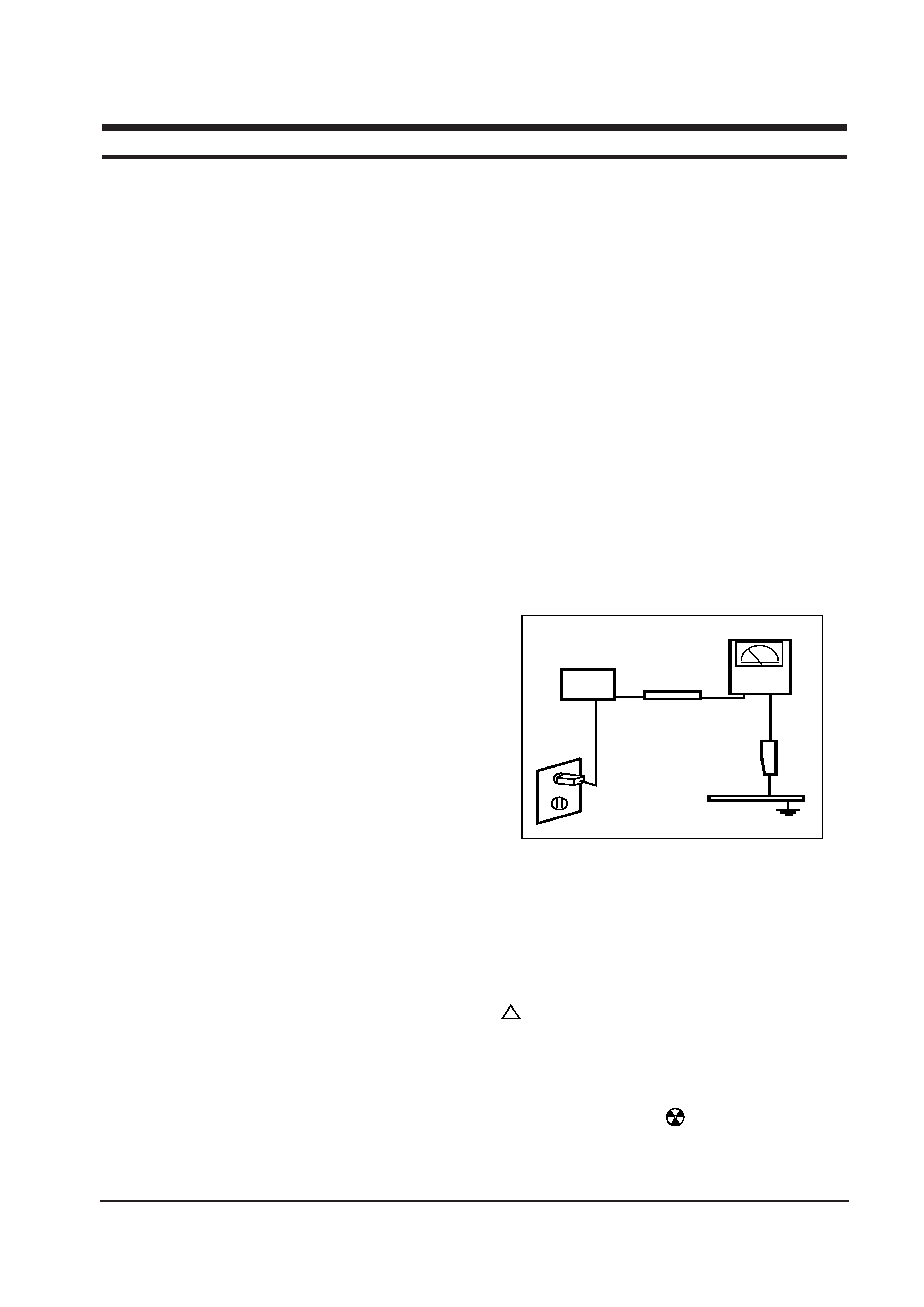
3.
Leakage Current Hot Check (Figure 1-1):
WARNING: Do not use an isolation transformer during
this test.
Use a leakage current tester or a metering system
that complies with American National Standards
Institute (ANSI C101.1, Leakage Current for
Appliances), and Underwriters Laboratories (UL
Publication UL1410, 59.7).
4.
With the unit completely reassembled, plug the AC
line cord directly into a 120V AC outlet. With the
unitÕs AC switch first in the ON position and then
OFF, measure the current between a known earth
ground (metal water pipe, conduit, etc.) and all
exposed metal parts, including: metal cabinets,
screwheads and control shafts. The current
measured should not exceed 0.5 milliamp. Reverse
the power-plug prongs in the AC outlet and repeat
the test.
Figure 1-1. Leakage Current Test Circuit
1-1-4 Product Safety Notices
Some electrical and mechanical parts have special
safety-related characteristics which are often not
evident from visual inspection. The protection they give
may not be obtained by replacing them with
components rated for higher voltage, wattage, etc. Parts
that have special safety characteristics are identified by
on schematics and parts lists. A substitute
replacement that does not have the same safety
characteristics as the recommended replacement part
might create shock, fire and / or other hazards. Product
safety is under review continuously and new
instructions are issued whenever appropriate.
Components identified by
on schematics and parts
lists must be sealed by a soldering iron after
replacement and adjustment.
CHA42*7L/5**7L
1-1
1 Precautions
1-1 Safety Precautions
!
DEVICE
UNDER
TEST
TEST ALL
EXPOSED METAL
SURFACES
(READING SHOULD
NOT BE ABOVE 0.5mA)
LEAKAGE
CURRENT
TESTER
2-WIRE CORD
ALSO TEST WITH
PLUG REVERSED
(USING AC ADAPTER
PLUG AS REQUIRED)
EARTH
GROUND
1.
Servicing precautions are printed on the cabinet,
and should be followed closely.
2.
Always unplug the unitÕs AC power cord from the
AC power source before attempting to: (a) remove
or reinstall any component or assembly, (b)
disconnect PCB plugs or connectors, (c) connect all
test components in parallel with an electrolytic
capacitor.
3.
Some components are raised above the printed
circuit board for safety. An insulation tube or tape
is sometimes used. The internal wiring is
sometimes clamped to prevent contact with
thermally hot components. Reinstall all such
elements to their original position.
4.
After servicing, always check that the screws,
components and wiring have been correctly
reinstalled. Make sure that the area around the
serviced part has not been damaged.
1.
Immediately before handling any semiconductor
components or assemblies, drain the electrostatic
charge from your body by touching a known earth
ground. Alternatively, wear a discharging wrist-
strap device. To avoid a shock hazard, be sure to
remove the wrist strap before applying power to
the monitor.
2.
After removing an ESD-equipped assembly, place it
on a conductive surface such as aluminum foil to
prevent accumulation of an electrostatic charge.
3.
Do not use freon-propelled chemicals. These can
generate electrical charges sufficient to damage
ESDs.
4.
Use only a grounded-tip soldering iron to solder or
desolder ESDs.
5.
Use only an anti-static solder removal device. Some
solder removal devices not classified as Òanti-staticÓ
can generate electrical charges sufficient to damage
ESDs.
5.
Check the insulation between the blades of the AC
plug and accessible conductive parts (examples:
metal panels, input terminals and earphone jacks).
6.
Insulation Checking Procedure: Disconnect the
power cord from the AC source and turn the power
switch ON. Connect an insulation resistance meter
(500 V) to the blades of the AC plug.
The insulation resistance between each blade of the
AC plug and accessible conductive parts (see
above) should be greater than 1 megohm.
7.
Never defeat any of the +B voltage interlocks. Do
not apply AC power to the unit (or any of its
assemblies) unless all solid-state heat sinks are
correctly installed.
8.
Always connect a test instrumentÕs ground lead to
the instrument chassis ground before connecting the
positive lead; always remove the instrumentÕs
ground lead last.
6.
Do not remove a replacement ESD from its
protective package until you are ready to install it.
Most replacement ESDs are packaged with leads
that are electrically shorted together by conductive
foam, aluminum foil or other conductive materials.
7.
Immediately before removing the protective
material from the leads of a replacement ESD,
touch the protective material to the chassis or
circuit assembly into which the device will be
installed.
Caution: Be sure no power is applied to the
chassis or circuit and observe all
other safety precautions.
8.
Minimize body motions when handling
unpackaged replacement ESDs. Motions such as
brushing clothes together, or lifting your foot from
a carpeted floor can generate enough static
electricity to damage an ESD.
9.
Indicates ESDs on the Schematic Diagram in
this manual.
1 Precautions
1-2
CHA42*7L/5**7L
1-3 Electrostatically Sensitive Devices (ESD) Precautions
Some semiconductor (solid state) devices can be easily damaged by static electricity. Such components are commonly
called Electrostatically Sensitive Devices (ESD). Examples of typical ESD devices are integrated circuits and some field-
effect transistors. The following techniques will reduce the incidence of component damage caused by static electricity.
1-2 Servicing Precautions
WARNING1: First read the "Safety Precautions" section of this manual. If unforeseen circumstances
create conflict between the servicing precautions and safety precautions, always
follow the safety precautions.
WARNING2: An electrolytic capacitor installed with the wrong polarity might explode.
CHA42*7L/5**7L
2-1
2 Reference Information
2-1 List of Abbreviations, Symbols and Acronyms
2-1-1 Abbreviations
Abbreviation
Definition
Abbreviation
Definition
ASS'Y
Assembly
B
Blue
B+ ADJ
B+ Adjustment
B-CUT
Blue-Cutoff
B-GAIN
Blue Gain
BRIGHT
Brightness
C
R-Composition
C-MIC
Condenser Microphone
CLK
Clock
CM
R-Cement
CN
Connector
CONT
Contrast
D-SUB
D-Subminiature
EEP-CLK
Electrically Erasable and
Programmable Clock
EXT
External
EXT-MIC
External Microphone
Freq.
Frequency
FU
Fusible
G
Green
G-CUT
Green-Cutoff
G-GAIN
Green Gain
GND
Ground
H
Horizontal
H
Heater
H-DRV
Horizontal Drive
H-DY
Horizontal Deflection York
H-FLB
Horizontal Flyback
H-FV
Horizontal-Feedback Voltage
H-LIN
Horizontal Linearity
H-POSI
Horizontal Position
H-SIZE
Horizontal Size
H/PHONE
Headphone
Hz
Hertz
I-SENSE
Current-Sense
lb
Pound
MAX
Maximum
MIC
Microphone
MIN
Minimum
MP
C-Metalized Polyester
MPP
Metal Polypropylene
MO
R-Metal Oxide
OSC
Oscillator
P
C-Polyester
PARA
Parabola
PARALL
Parallelogram
PIN-BAL
Pincushion Balance
PRE-AMP
Pre-Amplifier
PS1
Power Saving1 (suspend)
PS2
Power Saving2 (off)
PWR
Power
R
Red
R-CUT
Red-Cutoff
R-GAIN
Red Gain
RST
Reset
S-PIN
Side Pincushion
S-RASTER
Self Raster
S/W
Switch
SCAP
S Correction Capacitor
SPK
Speaker
SYNC
Synchronization
T
C-Tantalum
TR
Transistor
TRAP
Trapezoid
U-COM
Microprocessor
V
Vertical
V-DY
Vertical Deflection York
V-FLB
Vertical Flyback
V-LIN
Vertical Linearity
V-MUTE
Video Mute
V-OUT
Vertical Output
V-PARA
Vertical Parabola
V-POL
V-Polarity
V-POSI
Vertical Position
V-SENSE
Voltage-Sense
V-SIZE
Vertical Size
WW
R-Wire Wound
X-TAL
Crystal
ohm
K
1000 ohm
M
1000 K
uF
microfarad (10-6F)
nF
nanofarad (10-9F)
pF
picofarad (10-12F)