For Customer Use:
Enter below the Serial No. which is
located on the body. Retain this
information for future reference.
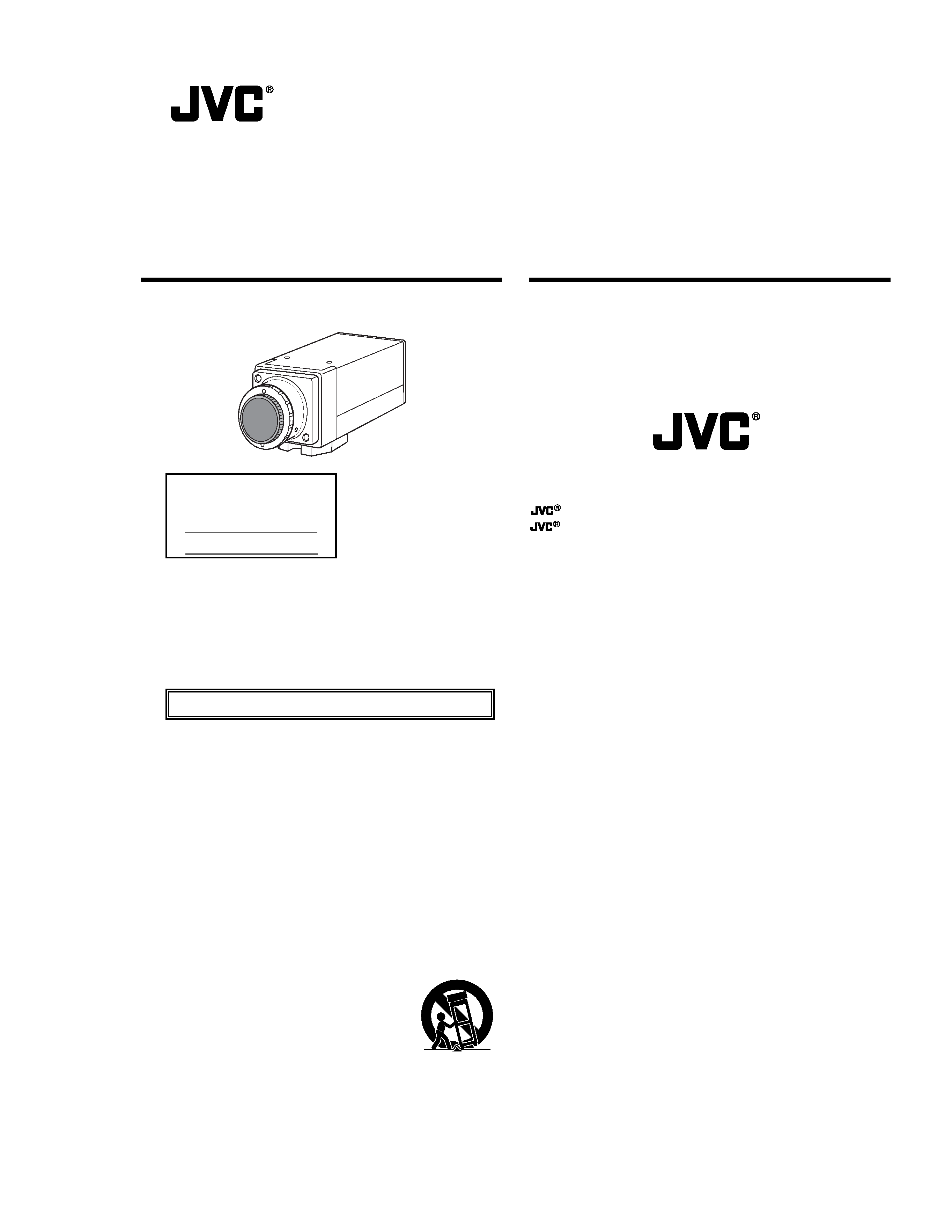
Model No. TK-WD310
Serial No.
COLOR VIDEO CAMERA
TK-WD310 INSTRUCTIONS
LWT0127-001A
This instruction manual is made from 100% recycled paper.
I
IMPORTANT SAFEGUARDS
1. Read all of these instructions.
2. Save these instructions for later use.
3. All warnings on the product and in the operating instructions
should be adhered to.
4. Unplug this appliance system from the wall outlet before clean-
ing. Do not use liquid cleaners or aerosol cleaners. Use a damp
cloth for cleaning.
5. Do not use attachments not recommended by the appliance
manufacturer as they may cause hazards.
6. Do not use this appliance near water - for example, near a
bathtub, washbowl, kitchen sink, or laundry tub, in a wet base-
ment, or near a swimming pool, etc.
7. Do not place this appliance on an unstable cart, stand, or table.
The appliance may fall, causing serious injury to a child or adult,
and serious damage to the appliance.
Use only with a cart or stand recommended
by the manufacturer, or sold with the appli-
ance. Wall or shelf mounting should follow
the manufacturer's instructions, and should
use a mounting kit approved by the manu-
facturer. An appliance and cart combination
should be moved with care.
Quick stops, excessive force, and uneven sur-
faces may cause the appliance and cart com-
bination to overturn.
PORTABLE CART WARNING
(symbol provided by RETAC)
S3125A
II
8. Slots and openings in the cabinet and the back or bottom are
provided for ventilation, and to insure reliable operation of the
appliance and to protect it from overheating, these openings
must not be blocked or covered. The openings should never be
blocked by placing the appliance on a bed, sofa, rug, or other
similar surface.
This appliance should never be placed near or over a radiator
or heat register. This appliance should not be placed in a built-
in installation such as a bookcase unless proper ventilation is
provided.
9. This appliance should be operated only from the type of power
source indicated on the marking label. If you are not sure of the
type of power supplied to your home, consult your dealer or
local power company. For appliance designed to operate from
battery power, refer to the operating instructions.
10. For added protection for this product during a lightning storm,
or when it is left unattended and unused for long periods of
time, unplug it form the wall outlet and disconnect the antenna
or cable system. This will prevent damage to the product due to
lightning and power-line surges.
11. Do not allow anything to rest on the power cord. Do not locate
this appliance where the cord will be abused by persons walk-
ing on it.
VICTOR COMPANY OF JAPAN, LIMITED
Printed in Japan
LWT0127-001A
© 2004 VICTOR COMPANY OF JAPAN, LIMITED
is a registered trademark owned by VICTOR COMPANY OF JAPAN, LTD.
is a registered trademark in Japan, the U.S.A., the U.K. and other countries.
TK-WD310
COLOR
VIDEO
CAMERA
III
12. Follow all warnings and instructions marked on the appliance.
13. Do not overload wall outlets and extension cords as this can
result in fire or electric shock.
14. Never push objects of any kind into this appliance through cabi-
net slots as they may touch dangerous voltage points or short
out parts that could result in a fire or electric shock. Never spill
liquid of any kind on the appliance.
15. Do not attempt to service this appliance yourself as opening or
removing covers may expose you to dangerous voltage or other
hazards. Refer all servicing to qualified service personnel.
16. Unplug this appliance from the wall outlet and refer servicing
to qualified service personnel under the following conditions:
a. When the power cord or plug is damaged or frayed.
b. If liquid has been spilled into the appliance.
c. If the appliance has been exposed to rain or water.
d. If the appliance does not operate normally by following the
operating instructions. Adjust only those controls that are
covered by the operating instructions as improper adjust-
ment of other controls may result in damage and will often
require extensive work by a qualified technician to restore
the appliance to normal operation.
e. If the appliance has been dropped or the cabinet has been
damaged.
f. When the appliance exhibits a distinct change in performance
- this indicates a need for service.
IV
17. When replacement parts are required, be sure the service tech-
nician has used replacement parts specified by the manufac-
turer that have the same characteristics as the original part.
Unauthorized substitutions may result in fire, electric shock, or
other hazards.
18. Upon completion of any service or repairs to this appliance,
ask the service technician to perform routine safety checks to
determine that the appliance is in safe operating
condition.
V
Safety Precautions
FOR USA AND CANADA
RISK OF ELECTRIC SHOCK
DO NOT OPEN
CAUTION
CAUTION: TO REDUCE THE RISK OF ELECTRIC SHOCK. DO NOT REMOVE
COVER
(OR
BACK). NO
USER-SERVICEABLE
PARTS
INSIDE.REFER SERVICING TO QUALIFIED SERVICE PERSONNEL.
The lightning flash wish arrowhead symbol, within an equi-
lateral triangle is intended to alert the user to the presence
of uninsulated "dangerous voltage" within the product's en-
closure that may be of sufficient magnitude to constitute a
risk of electric shock to persons.
The exclamation point within an equilateral triangle is in-
tended to alert the user to the presence of important oper-
ating and maintenance (servicing) instructions in the litera-
ture accompanying the appliance.
Information for USA
This device complies with part 15 of the FCC Rules. Changes or modifica-
tions not approved by JVC could void the user's authority to operate the
equipment.
VI
Due to design modifications, data given in this instruction book are sub-
ject to possible change without prior notice.
WARNING:
TO REDUCE THE RISK OF FIRE OR ELECTRIC
SHOCK, DO NOT EXPOSE THIS APPLIANCE TO
RAIN OR MOISTURE.
AVERTISSEMENT:
POUR EVITER LES RISQUES D'INCENDIE OU
D'ELECTRO-CUTION,
NE
PAS
EXPOSER
L'APPAREIL A L'HUMIDITE OU A LA PLUIE.
INFORMATION (FOR CANADA)
RENSEIGNEMENT (POUR CANADA)
This Class B digital apparatus complies with Canadian ICES-003.
Cet appareil numérique de la Class B est conforme á la norme NMB-003
du Canada.

2
Thank you for purchasing this product.
(These instrustions are for TK-WD310U and TK-WD310E.)
Before beginning to operate this unit, please read the instruction
manual carefully in order to make sure that the best possible perfor-
mance is obtained.
Features
Backlight compensation over a wide area is realized by the 14-bit Wide
Dynamic Range feature.
The Wide Dynamic Range feature controls the exposure time using a
maximum of 5 sampling timing for the image within a single screen.
Even when shooting in areas with large difference in lightning, subjects
with difference in brightness can be viewed in a clear and natural state.
1/3-inch high-resolution DPS device adopted as shooting element to
realize high picture quality with no smearing or blooming in areas with
high luminance. In addition, 2.5lx (during F1.2, 50%, AGC SUPER set-
ting) is realized for minimum subject brightness.
Horizontal resolution of 480 lines (typ.) and vertical resolution of over
400 lines allow display of finely detailed video.
New device adopted for use even under strong electric field conditions.
Compatible with CS mount and VIDEO auto iris/DC auto iris.
* When using the C mount lens, C mount adapter is required.
Various settings in each menu screen are possible.
Menu settings can be performed easily using single button operations.
3 white balance modes of ATW, AWB and MANUAL are available.
ATW mode that adjusts the white balance automatically according to
the changes in lighting conditions (color temperature) or AWB/MANUAL
mode that automatically or manually adjusts and locks the white bal-
ance of specific lighting conditions can be selected.
Camera title setting and display can be made.
Compact design allows installation in narrow spaces.
INTRODUCTION
3
Before starting an important recording, be sure to perform a
test recording in order to confirm that a normal recording is
possible.
We do not accept liability for the loss of a recording in the
case of it becoming impossible to record due to a problem
in the video camera, VCR or video tape.
We do not accept liability for any damage to the camera in
cases when it is dropped because of incomplete installation
due to not observing the installation instructions correctly.
Please be careful when installing the camera.
Characters and symbols used in this instruction manual.
CAUTION : Cautionary notes concerning operation of the
unit.
MEMO
: Reference such as restrictions of features, etc.
: Reference page or item.
EASY INSTALLATION
The factory default settings are intended to give easy instal-
lation. Please attach a lens, a power supply, a video cable
and mount the camera securely. You should now have good
images.
The additional information contained in this handbook is intended
to give additional flexibility to more demanding installations.
4
Contents
INTRODUCTION
Features ..................................................................................... 2
Contents ..................................................................................... 4
Operating Precautions ............................................................... 5
Names and Operations of Parts ................................................. 8
CONNECTION/INSTALLATION
Basic System ........................................................................... 13
Mounting the lens ..................................................................... 14
Connections on the back .......................................................... 16
Mounting the camera ............................................................... 18
Auto iris lens adjustment .......................................................... 20
Back focus adjustment ............................................................. 22
MENU SETTING
Menu settings ........................................................................... 24
Menu tree ................................................................................. 26
About menus ............................................................................ 27
FOCUS ADJUST screen .......................................................... 27
VIDEO ADJUST screen ........................................................... 28
WDR CUSTOM SETTINGS screen ...................................... 29
MANUAL WHITE BALANCE screen ..................................... 33
CAMERA SETTINGS screen ................................................... 34
LENS ADJUST screen .......................................................... 34
CAMERA TITLE EDIT screen ............................................... 36
FACTORY SETTINGS screen .................................................. 38
OTHERS
Troubleshooting ........................................................................ 39
Speifications ............................................................................. 40
5
Operating Precautions
To save energy, when it is not being used turn the system's
power off.
This camera has been designed for indoor use.
When you use it outdoors, be sure to use an appropriate housing.
Do not install or use the camera in the following places.
· In a place exposed to rain or moisture.
· In a place with vapor or oil soot, for example in a kitchen.
· When the ambient temperature rises above or falls below the
acceptable range (from 10°C to 50°C).
· Near a source of radiation, X-rays, strong radio waves or mag-
netism.
· In a place where corrosive gasses are generated.
· In a place subject to vibration.
· In a place with excessive dirt.
If this camera and the cables connected to this camera are used
where there are strong electromagnetic waves or where there
is magnetism present, for example near a radio or TV transmit-
ter, power transformer or an electric motor, the picture may pro-
duce noise and the colours may be affected.
This camera incorporates an AGC circuit. As a result, when it is
used under low light conditions, the camera sensitivity is auto-
matically boosted and the picture may look uneven. However,
this is not a malfunction.
When this camera is used in the ATW mode, the recorded
colours may be slightly different from the actual colours due to
the operational principles of the auto-tracking white balance cir-
cuit. However, this is not a malfunction.
Hunting may occur depending on the used lens. However, this
is not a malfunction of the unit.
The screen surroundings may appear dark depending on the
used lens.
INTRODUCTION
6
Operating Precautions (continued)
The white balance (ATW) of this device is optimally set for sun-
light. Proper white balance may not be achieved for artificial
lighting such as fluorescent lighting, etc.
If you use this camera in locations where the camera is ex-
posed to fluorescent light, a slow color change may occur.
(White balance normal = 5,400 K, range is 2,500 K to 10,000 K.)
AGC SUPER: in this mode, ATW white balance may be inaccurate.
White balance performance decreases under poor lighting con-
ditions.
Observe the following when carrying out camera maintenance.
·Turn the power OFF before proceeding to carry out mainte-
nance.
If it is contaminated seriously, clean the contaminated part with
a cloth (or a tissue) which has been soaked in a solution of
water and a neutral detergent.
The unit is to be powered by a DC 12 V or an AC 24 V power
supply.
The AC 24 V power supply should conform to the following:
U type : Class 2 only
E type : Isolated power supply only
The beat may sometimes appear on the screen if gain is raised
when the line lock is in use, but the phenomenon takes place
due to the fluctuation of power frequency and is not a malfunc-
tion.
At Low light levels, video iris lens may "Hunt". Please adjust iris
level on lens to minimise hunting.
Recommended range of operating temperature is 0°C to 35°C
degrees. The camera will function outside these parameters to
10°C to 50°C degrees. But processing errors may be appar-
ent.
INTRODUCTION
7
Line-Lock is set for 50 Hz ±0.02 Hz. If line frequency is outside
this tolerance, picture may jitter and some interference may be
visible in high contrast scenes.
Blemishes: Small spots are normal, the camera contains com-
pensation functions for blemishes above 120 mV (p-p) in value.
Please contact your JVC authorised dealer for further informa-
tion.
8
INTRODUCTION
Names and Operations of Parts
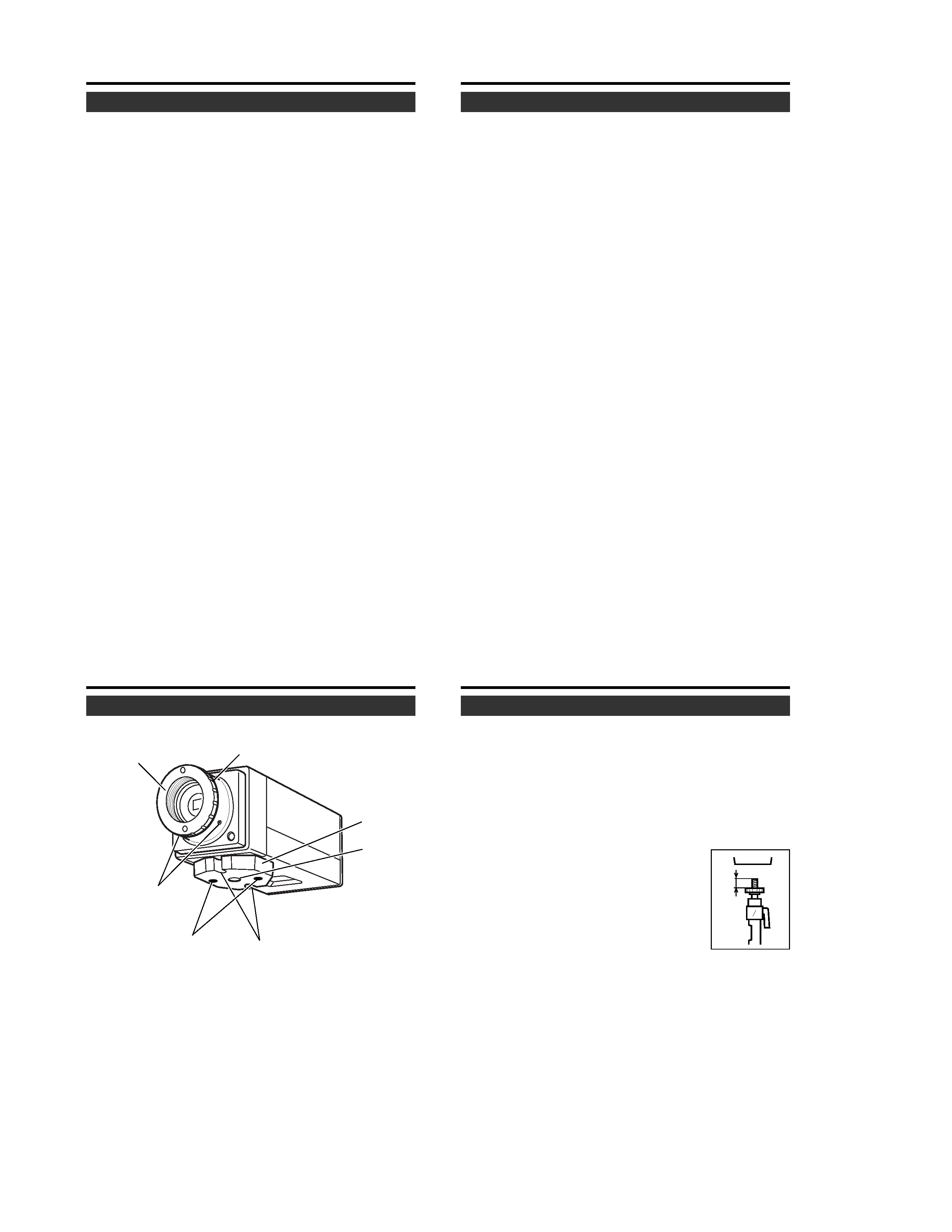
[Front and Bottom]
1 Lens mount
For use with CS mount lens.
(C-mount lenses require a conversion ring.)
2 Backfocus adjustment ring
Adjusting the back focus during lens installation.
Please refer to "Back focus adjustment" on
Page 22 for in-
structions on how to adjust the back focus.
3
1
2
4
5
6
7
9
3 [BF LOCK] Back focus locking screw (× 2: 2 mm)
This serves to fix the back focus-adjusting ring.
4 Camera-mounting bracket
The bracket has been attached on the bottom of the camera
before shipment. It can also be attached on the top according
to the circumstance.
To re-attach the bracket use the threaded holes at the top, with
the camera mounting bracket locking screws
7.
5 Camera-mounting screw hole (1/4 inch)
Use this hole when mounting the camera
onto a fixer, pan/tilt unit, and the like.
(Use a screw shorter than 7 mm.)
(
Page 18)
6 Rotation prevention hole
Make use of this rotation-preventive hole to prevent any fall
when mounting the camera. Make sure that the camera is se-
curely mounted.
7 Camera mounting bracket fixing screws (× 2: M2.6 × 6 mm)
Be sure to use a 6 mm long screw.
Names and Operations of Parts
MAX.
7mm
10
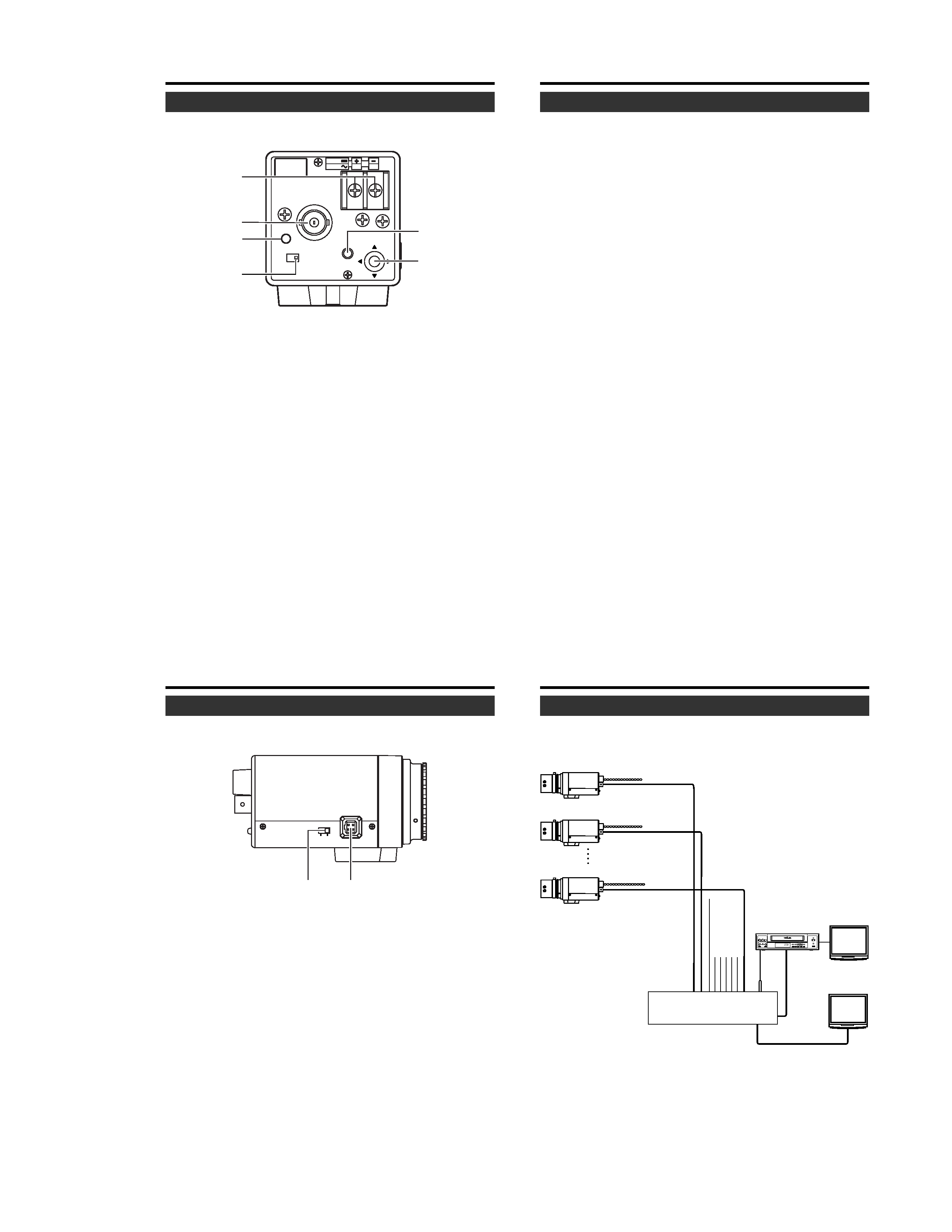
Names and Operations of Parts
[Rear Panel]
SEE INST-
RUCTION
MANUAL
DC12V
AC24V
1
2
CLASS 2 ONLY (U TYPE)
ISOLATED POWER ONLY
(E TYPE)
POWER VIDEO OUT
INT
LL
SET
SELECTOR
8 [DC 12V, AC 24V] Power input terminals
To input DC 12V or AC 24V power.
9 [VIDEO OUT] Video signal output connector
This BNC connector outputs a composite video signal. Con-
nect this to the video input connector of a video monitor,
switcher, etc.
0 [POWER] Power indicator lamp
This lamp lights when power is supplied to the camera.
INTRODUCTION
A
B
8
9
C
0
11
A [SET] button
During normal screen display, pressing and holding this button
for more than 2 seconds will display the MENU screen.
(
Page 24)
During MENU screen display, this button is pressed to display
or enable the selected menu item. The input digit will change
when entering the camera title.
When selecting EXIT in the TOP MENU screen, pressing this
button will return to the normal screen.
B [SELECTOR] button
Used when performing menu settings.
This button is a multidirectional switch.
Pressing in a vertical direction (
6 or 7) will select the menu
item.
Pressing in a horizontal direction (
8 or t) will change the
set value of the item. When entering the camera title, the
input character will change.
C [INT/ LL] Selector Switch for Synchronizing System
This switch can set a synchronizing system of the camera.
INT:
This is set for internal synchronization (INT) .
LL (Line Lock):
The camera's vertical synchronization is locked to the AC 24V
power line frequency.
When switching between multiple cameras using a switcher,
selecting this mode and adjusting the vertical phase can re-
duce the monitor sync disturbances occurring when the cam-
era image is switched. (This cannot be used in regions where
the power frequency is 50 Hz (60 Hz) . ( ): TK-WD310E)
(INT: At time of factory shipment)
12
Names and Operations of Parts
[Side Panel]
COLOR VIDEO CAMERA
IRIS
DC
VIDEO
D [VIDEO/DC] Iris Selector Switch
This should be set according to the type of lens if an automatic
iris control lens is used.
VIDEO : In case of lens with EE amp built-in.
(
Page 20)
DC
: In case of lens without EE amp built-in.
(
Page 14)
(DC : At time of factory shipment)
E [IRIS] Iris Terminal
This is connected to an automatic iris control lens.
(
Page 15)
INTRODUCTION
D
E
13
Basic System
System with up to 8 cameras
REC
PLAY
FF
REW
REVERSE
PAUSE/
STILL
REC
CHECK
STOP/EJECT
COUNT/
CLOCK
TIME
MODE
TIMER
REC
AL/PL
RESET
MENU
VIDEO CASSETTE RECORDER
SHIFT/TRACKING
SET/V.LOCK
RESET
/CANCEL
OPERATE
SR-L910
OPE. LOCK
· ·····
COLOR VIDEO CAMERA
ALC
LEVEL
Av
Pk
L
H
COLOR VIDEO CAMERA
ALC
LEVEL
Av
Pk
L
H
COLOR VIDEO CAMERA
ALC
LEVEL
Av
Pk
L
H
Switcher
Video signal cable
Power
cable
AC24V or
DC12V
AC24V or
DC12V
AC24V or
DC12V
Camera 1
Camera 2
Camera 8
Monitor
Monitor
DVR, etc.
CONNECTION/INSTALLATION